
2.5 Given a scenario, install and configure basic wired/wireless small office / home office (SOHO) networks
- Internet Protocol (IP) Addressing
- IPv4
- Public Addresses
- Private Addresses
- IPv6
- Automatic Private IP Addressing (APIPA)
- Static
- Dynamic
- APIPA
- Gateway
- IPv4
Basic Router Configuration
How do we configure a router? We covered configuration in a previous section, but let’s summarize.
- Power on the router/switch
- Connect the router’s WAN port to the ISPs modem
- Configure the name of the router
- Configure the WAN IP address of the router based on details from the ISP, including
- DHCP or Static
- If static, add IP address, gateway address, subnet mask, DNS server addresses
- Configure IP address for the router
- Configure size/class of network
- Configure DHCP (we will discuss DHCP later)
- Provide a range of addresses that will be part of DHCP pool
- Configure DHCP reservations based on MAC address if necessary
- Provide a range of addresses that will be part of DHCP pool
- Configure remote management if needed
Basic Switch Configuration
How do we configure a switch? If the switch is unmanaged, then no configuration is possible.
- Connect switch to router’s LAN port via ethernet cable
- Power on switch
- Configure switch name
- Configure switch IP address
- Configure security rules for switch
- For each port
- Configure VLANs handled by port
- Configure port name/description
- Configure port security
- Configure PoE
- Shutdown unused ports
Access Point Settings
How do we configure an access point?
- Install antennas if necessary
- Mount Access Point to wall/ceiling, or another appropriate place
- Connect Access Point to switch
- Connect Access Point to Power Injector or AC/DC adapter if switch does not support PoE
- Configure settings
- Configure SSIDs (may have multiple SSIDs)
- Select security type (WPA, WPA2, WPA Enterprise) for each SSID
- Decide if the SSID will be hidden
- Select password, or connect AP to authentication server
- Configure security such as whitelists, blacklists, or MAC address filtering
- Configure guest Wi-Fi, if necessary
- Configure power settings
- Choose between 2.4GHz and 5GHz or both
- Choose channel
- Choose broadcast power
- In a larger system, the APs may automatically adjust their channel and/or broadcast power
If the access point is cloud managed, then all we need to do is plug it in. We would configure general settings in the cloud manager, but the wireless access points will work together.
IoT Device Configuration
How do we configure an IoT device?
- Tens of thousands of IoT devices are available on the market; this is not an exhaustive list, just a general idea
- There are two main configuration parameters for an IoT device
- Network connection (static vs DHCP, and ethernet vs Wi-Fi) – how does it connect to the internet?
- Other parameters specific to the device (thermometer temperature, camera recording time, etc.)
- Network connection (static vs DHCP, and ethernet vs Wi-Fi) – how does it connect to the internet?
- Network connection
- There are several ways that a network connection can be configured, depending on the device – ethernet or Wi-Fi
- If it is an Ethernet-connected device
- Most PoE devices such as cameras use Ethernet
- Connect the device to the network and allow it to power on
- Device will automatically obtain an IP address over DHCP, or it might be configured with a static IP address
- Use a network scanner or check the router’s status page to determine IP address assigned to device.
- Go to the IP address in a web browser to access the device’s configuration page
- Find the network settings page and change IP address to static. Why? It is easier to locate and connect to the device in the future, set up port forwarding, and connect the device to other systems.
- Most PoE devices such as cameras use Ethernet
- If it is a Wi-Fi device with user interface/touchpad
- Access settings menu from device’s screen
- Select the correct Wi-Fi SSID and insert password
- Allow the device to connect to Wi-Fi
- Change IP address to static
- Access settings menu from device’s screen
- If it is a Wi-Fi device with no user interface – USB
- Power on device
- Connect device to computer via USB and run software setup wizard
- Wizard will copy correct Wi-Fi/IP address settings to device
- Allow device to connect to Wi-Fi
- Device will begin operating
- Power on device
- If it is a Wi-Fi device with no user interface – ad hoc Wi-Fi
- When you power up the device for the first time, it will broadcast a unique SSID (as a Wi-Fi network)
- Connect to the SSID from a laptop or smart phone
- Browse to the configuration page via a web browser or run a software setup wizard (usually a pre-configured IP address)
- The device will have a wizard that will copy Wi-Fi/IP address/configuration settings from your router
- Disconnect from the device’s Wi-Fi to allow it to connect to your existing wireless network
- When you power up the device for the first time, it will broadcast a unique SSID (as a Wi-Fi network)
- There are several ways that a network connection can be configured, depending on the device – ethernet or Wi-Fi
- Other Configurations
- Once a device is connected to the network/cloud, there may be three ways to configure it
- Visit the IP address of the device in a web browser to access configuration page
- User interface (screen/buttons) if device has one
- Cloud website / app if device connects to an external service
- Visit the IP address of the device in a web browser to access configuration page
- Once a device is connected to the network/cloud, there may be three ways to configure it
- Other parameters
- Thermostat
- Example includes Nest thermostat
- Configure temperatures and schedules
- Light Switch
- Example includes Leviton light switches
- Configure schedule for turning lights on/off, and LED colors
- Security Camera
- Example includes Ring.com cameras
- Configure recording time, sensitivity, alerts for when camera detects motion
- Door Lock
- Example includes Yale lock
- Configure password, keys, authorized users, schedules
- Digital Assistant
- Example includes Amazon Alexa
- Configure name, authorized users
- Digital Assistants typically have artificial intelligence and record all interactions, so that they can become smarter over time
- Thermostat
Cable/DSL Modem Configuration
- A modem usually downloads its configuration from the ISP automatically
- If the modem fails, you can perform a factory reset on the modem, and it will redownload its configuration
- Modem with additional functions (router, switch, AP) can be configured as per those settings (already discussed)
Firewall Settings
There are four components to a firewall configuration
- ACL or Access Control List. The Access Control List is a set of rules for what traffic is permitted to pass and what traffic is not permitted. There are many types of rules, based on
- Source IP address. Where is the traffic coming from? The source IP address could be on the LAN or on the WAN. It could be a specific IP address or a range of addresses.
- Destination IP address. Where is the traffic going? The destination IP address could be on the LAN or on the WAN. It could be a specific IP address or a range of addresses.
- Source Port Number. What is the port number of the source traffic? The source port could be on the LAN or on the WAN. It could be a specific port or a range of ports.
- Destination Port Number. What is the port number of the destination traffic? The destination port could be on the LAN or on the WAN. It could be a specific port or a range of ports.
- Username. Access Control Lists can be user-based. Permissions can be granted or denied to specific users based on their needs in the organization. For example, guests can be permitted to access only the internet and not resources such as remote desktop or SQL servers.
- Rules can be specific or could combine a combination of parameters
- For example, a rule could say ‘Allow traffic from 10.1.1.1, port 5 to the range of IPs 192.168.3.0 to 192.168.3.255’. All traffic received from 10.1.1.1 port 5 will be permitted to access destinations in the range of 192.168.3.0 to 192.168.3.255. Traffic from other source IP addresses and/or ports will be rejected. Traffic from 10.1.1.1 to destinations outside of 192.168.3.0 and 192.168.3.255 will be rejected.
- Always Allow. An Always Allow rule allows all traffic matching a rule. For example, “always allow traffic from the source IP 10.1.1.1”. All traffic from 10.1.1.1 will be permitted regardless of the port number or destination.
- Always Deny. An Always Deny rule denies all traffic matching a rule. For example, “always deny traffic from the source IP 10.1.1.1”. All traffic from 10.1.1.1 will be denied regardless of the port number or destination.
- For example, a rule could say ‘Allow traffic from 10.1.1.1, port 5 to the range of IPs 192.168.3.0 to 192.168.3.255’. All traffic received from 10.1.1.1 port 5 will be permitted to access destinations in the range of 192.168.3.0 to 192.168.3.255. Traffic from other source IP addresses and/or ports will be rejected. Traffic from 10.1.1.1 to destinations outside of 192.168.3.0 and 192.168.3.255 will be rejected.
- Order of Operations
- A firewall could have dozens or thousands of rules. The rules are ranked in order of priority.
- When the firewall receives a piece of traffic, it starts checking the rules in order until it finds one that matches the traffic’s source and destination. It then applies that rule to the traffic.
- The firewall will only apply one rule to a piece of traffic. Once that rule is applied, the firewall stops checking additional rules.
- It is important to put the rules in logical order so that traffic is not accidentally accepted or rejected. When a firewall receives a piece of traffic that does not match any rules, it will either allow or reject the traffic based on its configuration.
- Many firewalls are preconfigured with two default rules
- Always allow traffic with a source inside the network (LAN)
- Always reject traffic with a source outside the network (WAN)
- Always allow traffic with a source inside the network (LAN)
- The two default rules should be put at the bottom of the list.
- The first rule (allowing all traffic from inside the LAN) is dangerous because users cannot be trusted to access only safe resources on the internet. It should be modified (broken down) into two rules.
- Always allow traffic with a
- Source inside the network (LAN)
- Destination outside the network (WAN)
- Limited to specific ports outside the network (port 80, port 443, port 3306, etc.). The specific ports should be based on resources that users need to access.
- Source inside the network (LAN)
- Always deny traffic
- Source inside the network (LAN)
- Destination outside the network (WAN)
- This rule applies second; any traffic not matching the previous rule will be denied
- Source inside the network (LAN)
- Always allow traffic with a
- The first rule (allowing all traffic from inside the LAN) is dangerous because users cannot be trusted to access only safe resources on the internet. It should be modified (broken down) into two rules.
- A firewall could have dozens or thousands of rules. The rules are ranked in order of priority.
- Source IP address. Where is the traffic coming from? The source IP address could be on the LAN or on the WAN. It could be a specific IP address or a range of addresses.
- Application-Based vs Network-Based
- An application-based firewall will analyse traffic on a deeper level than a network-based firewall
- The network-based firewall looks at traffic source and destination IP addresses, but the application-based firewall also looks at its contents
- The application-based firewall looks at the content of each packet before applying a rule.
- An analogy is a person who is screening mail. A network-based firewall would look at the to and from addresses on the envelope before deciding whether to forward the mail. An application-based firewall would open each envelope and look at the contents before deciding whether to forward the mail.
- Application-based firewalls can slow down traffic because they are analyzing the contents of each packet, which takes longer.
- An application-based firewall will analyse traffic on a deeper level than a network-based firewall
- Stateful vs Stateless
- Consider that almost all traffic on the internet is two-way traffic. When a user downloads a file from the internet, that file download is two-way. The downloader’s computer first makes a request to the server hosting the file (the sender). The sender’s computer breaks the file into packets and sends them one at a time. Each time the downloader’s computer receives a packet, it acknowledges receipt by sending a message. This is known as a connection (from TCP/IP).
- One party is responsible for originating each connection. In this case, the person who downloaded the file originated the connection (the person who is inside the network).
- A stateless firewall applies rules based only on the source and destination IP addresses and ports of the packets, but a stateful firewall will identify which party originated the connection (whether that party was inside the network or outside), and then block or allow it based on the source. A packet that is normally permitted or denied by an ACL may be denied or permitted by a stateful firewall.
- A stateful firewall requires additional hardware to process the decision making.
- Consider that almost all traffic on the internet is two-way traffic. When a user downloads a file from the internet, that file download is two-way. The downloader’s computer first makes a request to the server hosting the file (the sender). The sender’s computer breaks the file into packets and sends them one at a time. Each time the downloader’s computer receives a packet, it acknowledges receipt by sending a message. This is known as a connection (from TCP/IP).
- Implicit Deny
- As mentioned previously, a firewall lists its rules in order and applies the first rule that matches the traffic
- If the traffic does not match any rule, the firewall should deny it
- This is known as “implicit deny”
- The last rule in the list should be to deny all traffic.
- As mentioned previously, a firewall lists its rules in order and applies the first rule that matches the traffic
IP Addressing
I briefly mentioned IP addresses at the beginning of this book. Remember that each network device has a MAC address (assigned from the factory) and an IP address (assigned by the network)? We are going to learn where IP addresses come from and who regulates them.
An IP address has four sections, known as octets. For example, 192.168.0.4 is an IP address.
Each octet is a three-digit number separated by a period. The maximum value of an octet is 255 and the minimum value is 0. So, the range of IP addresses is from 0.0.0.0 to 255.255.255.255. How many IP addresses are there? 4,294,967,296. Are there enough IP addresses to go around if you consider that each person probably has a work computer, a home computer, a cell phone, and that there are many other servers and internet of things devices running in the background? Of course not.
A public IP address is one that is accessible from anywhere on the internet, and a private IP address is one that is only accessible from inside a local network. The devices on your local network (i.e., inside your home or office) probably have private IP addresses.
The router in your home or office probably has a public IP address assigned to the port that connects it with the outside world. The router probably also has a private IP address assigned to the port that connects it to the rest of your internal network.
Who decides what IP address you get? Your internet connection is assigned an IP address by your internet service provider. Your internet service provider is assigned a block of IP addresses by a larger organization (such as a larger ISP if they buy their internet from somebody else). At the top of the food chain is ARIN (American Registry for Internet Numbers).
ARIN assigns blocks of IP addresses to each ISP and to larger organizations. IPv4 addresses are scarce because there are more devices than IP addresses, and because in the early days of the internet, organizations were assigned large blocks of addresses. Nobody thought that the internet would grow to be as big as it is, so ARIN went crazy and gave everybody tons of IP addresses.
The US Department of Defense owns about 5% of the IPv4 addresses (addresses that start in 6, 7, 11, 21, 22, 26, 28, 29, 30, 33, 55, 214, and 215).
A few blocks of IP addresses have been reserved for private IP addresses and some blocks have been reserved for special functions as we will find out later.
The following IP address ranges are reserved for private use per RFC1918.
- 10.0.0.0 to 10.255.255.255
- 172.16.0.0 to 172.16.255.255
- 192.168.0.0 to 192.168.0.255
If you have an office or internal network, you can set up an internal addressing scheme by choosing one of the above three ranges. In my example office below, I chose the range 192.168.0.0 to 192.168.0.255. What range will you choose?
- 10.0.0.0 to 10.255.255.255 is the largest network, with a range of 16,581,375 possible addresses. This type of network is known as a class A network.
- 172.16.0.0 to 172.16.255.255 is the second largest network, with a range of 65,025 possible addresses. This type of network is known as a class B network.
- 192.168.0.0 to 192.168.0.255, is the smallest network, with a range of 256 addresses. This type of network is known as a class C network.
If we have a small network, we should choose a small range. Smaller network equipment (such as in a home or small business) might not be able to handle a larger range of IP addresses. As we will see later, we can subdivide a larger range into several smaller ranges and assign each one to a different function.
Let’s look at our example office. In our example, the ISP assigned us one public address: 44.3.2.1. Most of the IP address space is public. In theory, any device with a public IP can reach any other device with a public IP (unless a firewall blocks it). Thus, other devices on the internet can communicate with our network by contacting 44.3.2.1.
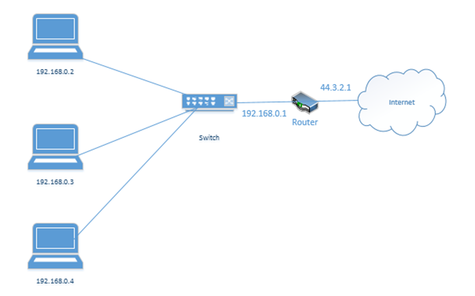
In my example office, there are three computers, with IP addresses of 192.168.0.2, 192.168.0.3, and 192.168.0.4. They connect to the switch. Notice that the router (which sits on the edge of the network) has a private IP address of 192.168.0.1 and a public IP address of 44.3.2.1. This allows the router to pass traffic between the private network and the public network. Devices within the private network can reach the router (and therefore the outside world) by contacting 192.168.0.1.
If our business was so large as to require multiple locations, we could choose the range 10.0.0.0 to 10.255.255.255 and then subdivide it further so that each location receives a block from our range. For example, one location receives the range 10.0.0.0 to 10.0.255.255, and the second location receives the range 10.1.0.0 to 10.1.255.255, etc. It might look like the drawing below
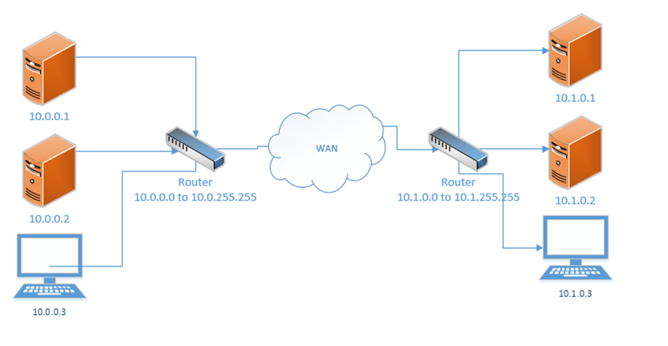
This would require us to implement a Wide Area Network or point-to-point VPN. The WAN allows us to configure the routers so that all the computers in all our offices think that they are on the same physical network.
Each local area network can use the same range of private IP addresses as any other network because a device on one LAN won’t talk directly with a device on another LAN. Instead, the pass their messages to their routers, which then deliver the traffic. If each router has a unique public IP address, we won’t encounter any issues.
So far, when we’ve been talking about IP addresses, we’ve been referring to IPv4 (version 4) IP addresses. But the world has been running out of IPv4 addresses, and so a new standard was created. This standard is known as IPv6.
In the IPv6 world, fc00::/7 is the only private range of IP addresses. It is better written as fc00:0000:0000:0000:0000:0000:0000:0000 to fdff:ffff:ffff:ffff:ffff:ffff:ffff:ffff.
How did I get from fc00::/7 to all that gibberish? We’ll find out later. But the point is, the range is massive. There is no need for each private network to have the same address as any other private network.
If we mash two private IPv4 networks together, we will have some conflicts. We will find that two devices have the same IP address, and one of them won’t be able to communicate. But if we mash two private IPv6 networks together, we won’t have any conflicts because each private IPv6 address is randomly generated. In fact, if mashed all the private IPv6 networks together, we probably won’t have any conflicts.
Loopback and Reserved
Some addresses are reserved. They can’t be assigned to anybody.
The addresses that are reserved
- 127.0.0.1 is called the loopback address (mapped to the hostname localhost). Every network device and computer consider 127.0.0.1 to belong to itself. If I send traffic from my computer to the address 127.0.0.1, it loops back and heads straight back to my computer.
What’s the point? Let’s say that my organization maintains two servers – a web server and a database server. The web server connects to the database server over the local network. If I decide to install the web server software and database software on the same physical machine, then I could reprogram the web server to look for the database server at the 127.0.0.1 address.
What if my server IP address is 192.168.0.1? Why do I need to specify 127.0.0.1? Why can’t I just tell the web server to look at 192.168.0.1? I could, but that would create unnecessary traffic along the network for a packet that doesn’t need to leave the server. Also, what happens if my server IP address changes frequently? I don’t want to reprogram the server every time the IP address changes. Or what if I don’t have an active network connection? What if I’m running a sensitive internal application but the application is looking for a network connection? I can specify 127.0.0.1.
127.0.0.1 is also used to test the internal operation of the network card. If I am troubleshooting a network connection, I might try to send traffic to 127.0.0.1. If it fails, I will know that the network problems are internal to the machine. - 0.0.0.0 to 0.255.255.255 is reserved for software testing.
- 169.254.0.0 to 169.254.255.255 is reserved for the link local IP addresses. This is a random IP address that a device assigns itself when it can’t find a DHCP server. That is, if a device joins a network and doesn’t have a preprogrammed IP address, and the network doesn’t assign it an IP address, it will randomly assign itself an IP address from that range.
- 255.255.255.255 is reserved for broadcasts. That is, when a device wants to send traffic (like an announcement) to all the other devices on its local network, it can send them to that address.
- There are other IP addresses that are reserved but to list them all would take forever.
On the IPv6 side
- ::1 also known as 0000:0000:0000:0000:0000:0000:0000:0001 is the loopback address
- fe80:0000:0000:0000:0000:0000:0000:0000 to febf:ffff:ffff:ffff:ffff:ffff:ffff:ffff is the link local address
- 2002:0000:0000:0000:0000:0000:0000:0000 to 2002:ffff:ffff:ffff:ffff:ffff:ffff:ffff was used by the 6to4 IP address conversion protocol. More on this later.
- ff00:0000:0000:0000:0000:0000:0000:0000 to ffff:ffff:ffff:ffff:ffff:ffff:ffff:ffff is the multicast address range. More on this later.
Default Gateway and Subnet Mask
Recall that we have public IP addresses and private IP addresses. When a device wants to send traffic to another device
- It first must ask itself: is this destination on my local network or is it somewhere else?
- If the destination is local, the computer sends the traffic to the switch, but with the MAC address of the destination device in the header. The switch forwards the traffic.

What happens when the destination is not local? Then the device must send the data to a router. But how does it know which router to send it to? And how does it know whether the destination device is local?
Every device has network settings, which include at least three items
- IP address – this is the IP address assigned to the device
- Subnet mask – this tells the device how big its local network is; the local network is known as a subnet
- Default gateway – this is another name for a router. In other words, the default gateway connects the local network with the outside world.
The device uses its IP address and the subnet to figure out the range of IP addresses in its local network. If the destination IP address is not in the local network, then it is sent to the default gateway.
This is going to be the hardest part of the book. Learning the complicated math about subnets. You don’t need to know it for the exam.
A subnet mask looks like an IP address. It is 32-bits long (each octet is 8-bits). Remember that computers are electrical. They only think in terms of “on or off”. So, a 1 is on, and a 0 is off.
8-bits makes up one byte. A computer with 8-bits can only count to 255 in one operation. If I make a table that is base-two (every entry is double the previous entry), I can combine these eight numbers to make any number from 0 to 255. Below is my table.
| 128 | 64 | 32 | 16 | 8 | 4 | 2 | 1 |
If you look at the 8-bits in a byte, each bit is assigned to one of the numbers in my table. If the bit is a one, or in “on’ position, then the number is added to the total, and if the bit is a zero, or in the “off” position, then the bit is ignored.
For example, my byte is 11011001. If we write this byte into the base-two table below, and add up the corresponding values,
| 128 | 64 | 32 | 16 | 8 | 4 | 2 | 1 |
| 1 | 1 | 0 | 1 | 1 | 0 | 0 | 1 |
The value of this byte is 128 + 64 + 16 + 8 + 1 = 217
Thus, we have two ways to write out this number, either as 217 or as 11011001
At its most basic level, when a processor is doing math, it has an electrical circuit that’s turning these different bits on and off.
So what? There is a small microprocessor inside each network card and router that thinks about IP addresses. This allows those devices to make subnet mask and IP address calculations quickly.
255.255.255.252 is an example of a subnet mask.
We could write it out as
11111111.11111111.11111111.11111100 if we wanted to. We call this a binary number. How did I get this? I simply went back to my table:
| 128 | 64 | 32 | 16 | 8 | 4 | 2 | 1 |
What numbers added equal 255? Well, if I start at the left, and work my way to the right, I found that I need all of them.
| 128 | 64 | 32 | 16 | 8 | 4 | 2 | 1 |
| 1 | 1 | 1 | 1 | 1 | 1 | 1 | 1 |
When the computer wants to express the number 255 in binary, it must turn on all the bits in the byte.
What about 252? To get to 252, the computer must turn on the first six bytes.
| 128 | 64 | 32 | 16 | 8 | 4 | 2 | 1 |
| 1 | 1 | 1 | 1 | 1 | 1 | 0 | 0 |
Now if we write out the binary value of each octet in the subnet mask, we get 11111111.11111111.11111111.11111100.
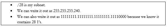
We could also call it a /30 subnet mask because it has 30 “1’s” in it. Note that you’ll never see a subnet mask like 255.255.255.217. In a subnet mask, the 1’s always appear on the left and the 0’s always appear on the right.
| 128 | 64 | 32 | 16 | 8 | 4 | 2 | 1 |
| 1 | 1 | 0 | 1 | 0 | 1 | 1 | 1 |
In binary, 217 is written as 11010111. Thus, the subnet mask 255.255.255.217 would be written as 11111111.11111111.11111111.11010111, which would put some 1’s to the right of some 0’s, which would be invalid.
Many network engineers like to reference a subnet mask as a “/30” or “/28” or “slash whatever number it is”, instead of saying the entire name.
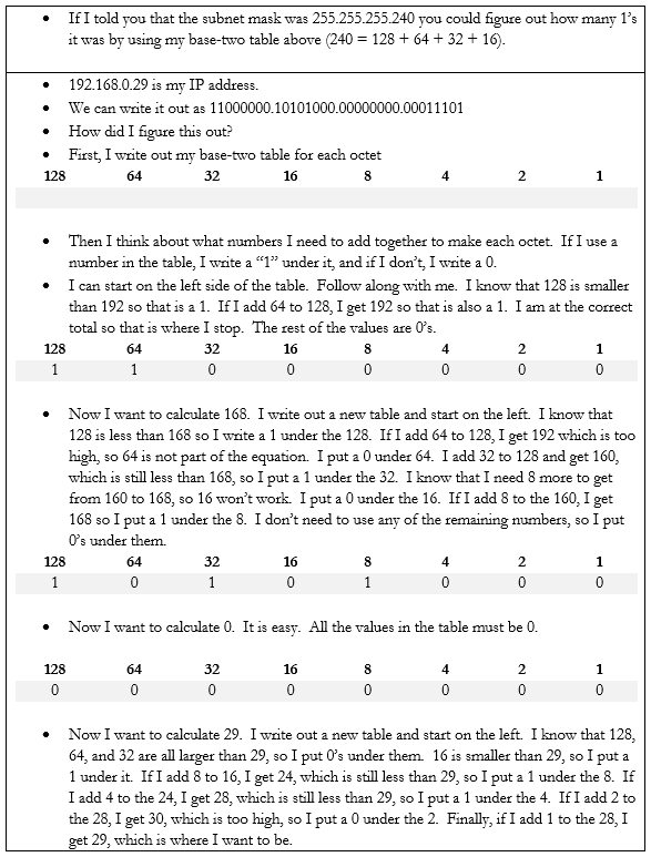
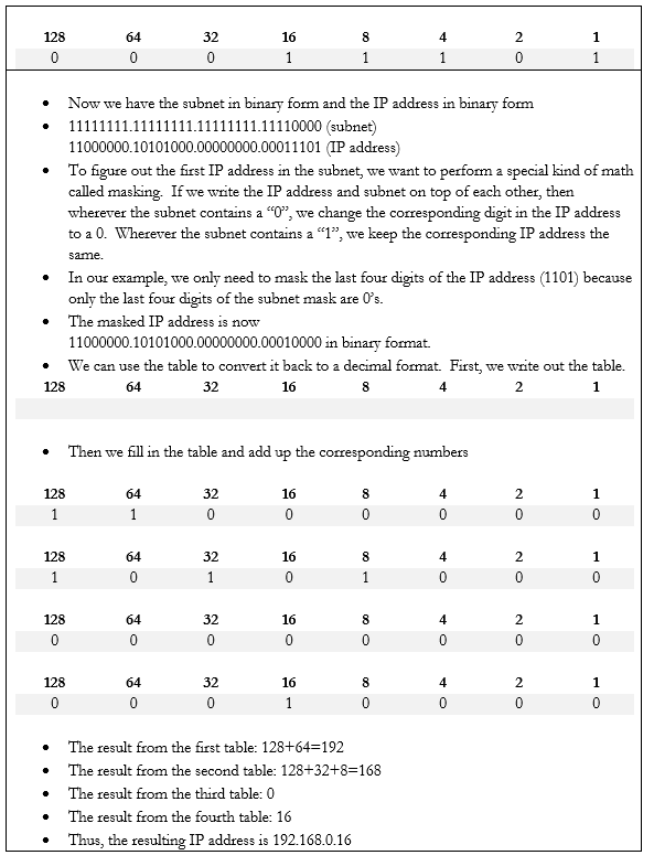
Let’s do an example. If my device IP address is 192.168.0.29 and my subnet mask is /28, how big is my network? What IP address does it start on and where does it end? We can figure it out.
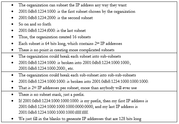
In the IPv6 scheme, there is no such thing as a subnet mask. If there was, the math would be complicated. But we do have subnets. We also have sub-subnets and sub-sub-subnets.
Some things to note about IPv6 addresses
- An IPv6 address is 128 bits wide (unlike an IPv4 which is 32 bits wide).
- Each “octet” in the IPv6 address is 4 characters wide, but each octet is 16 bytes wide (unlike an IPv4 octet which is one byte wide)
- An octet can contain numbers from 0 to 9 and letters from a to f. This is called hexadecimal because each place goes up to 16 with the letters. If I was counting in decimal, I could count 1, 2, 3, 4, 5, 6, 7, 8, 9. When I get to 9, I must move to the next place (10). If I was counting in hexadecimal, I would count 1, 2, 3, 4, 5, 6, 7, 8, 9, a, b, c, d, e f. When I get to f, I must move to the next place (10). My hexadecimal 10 is misleading because it is worth 16.
- There are eight octets in an IPv6 address.
- Each octet is separated by a colon
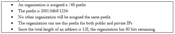
An IPv6 address has two parts. The first part is called the prefix. A /48 prefix is common.
For example,
Earlier I said that
- 10.0.0.0 to 10.255.255.255 is the largest network, with a range of 16,581,375 possible addresses. This type of network is known as a class A network.
- 172.16.0.0 to 172.16.255.255 is the second largest network, with a range of 65,025 possible addresses. This type of network is known as a class B network.
- 192.168.0.0 to 192.168.0.255, is the smallest network, with a range of 256 addresses. This type of network is known as a class C network.
The network classes apply to both public and private networks, not just the private ranges that I described above.
- A Class A network contains 224 addresses. Networks in the range of 1.0.0.0 to 126.0.0.0.0 are Class A networks. So, a network like 2.0.0.0 to 2.255.255.255 is a Class A network.
- A Class B network contains 216 addresses. Networks in the range of 128.0.0.0 to 191.0.0.0 are Class B networks. So, a network like 130.0.0.0 to 130.0.255.255 is a Class B network.
- A Class C network contains 28 addresses. Networks in the range of 192.168.0.0 to 223.0.0.0 are Class C networks. So, a network like 200.0.0.0 to 200.0.0.255 is a Class C network.
We have two more classes of networks
- Networks in the range of 224.0.0.0 to 239.0.0.0 are Class D networks.
- Networks in the range of 240.0.0.0 to 254.0.0.0 are Class E networks.
These networks do not have subnet masks. They are strictly experimental, and most routers will not accept traffic from IP addresses in their ranges. The use of a Class A, B, or C network is called Classful Subnetting.
The opposite is Classless Subnetting. How does it work?
If my network is 192.168.0.0 to 192.168.0.255, I have 256 IP addresses. I can break it down into one network of 256 addresses, or I can break it down into 2 networks of 128 addresses each, or 4 networks of 64 addresses each, or 8 networks of 32 addresses each, etc. If my network was a Class A or Class B network, I could break it down into even more subnets and/or have even more IP addresses per subnet.
| Subnet Mask | Number of IPs per Subnet | Number of Subnets |
| /24 | 254 | 1 |
| /25 | 126 | 2 |
| /26 | 62 | 4 |
| /27 | 30 | 8 |
| /28 | 14 | 16 |
| /29 | 6 | 32 |
| /30 | 2 | 64 |
There is no /31 or /32 subnet because we need at least three IP addresses in a subnet – the network ID, the useable IP, and the broadcast IP. A /31 subnet would be two IP addresses wide and a /32 subnet would be one IP address wide.
We could choose to break down our network into subnets of any size based on our requirements. We might want to create separate logical networks for each class of devices. This allows us to improve security by preventing a device on one subnet from communicating with a device on another subnet. It also makes it easier to manage the network.
We ask ourselves what the largest required subnet is and go from there. This is known as Fixed Length Subnetting. Looking at the above table, we have a few choices for how we can break down our network into equally sized subnets.
What if I need subnets of different lengths? Introducing the Variable Length Subnet Mask
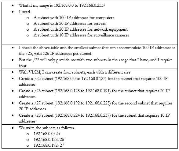

VSLM is part of a system called Classless Inter-Domain Routing, or CIDR. Writing the IP address with the subnet mask at the end as a slash is known as Classless Inter-Domain Routing Notation.
We can also write an IPv6 address in CIDR notation. Instead of writing the full IP address, we would write the IP address and subnet length. For example, we could write 2001:0db8:1234:0000:1111:2222:3333:4444 /48
Since we’re on the subject, let’s look at some other types of special IP addresses
- Broadcast. A broadcast is a message that is sent to all the devices in a single broadcast domain. That is, if my computer wants to send a message to all the other computers in the subnet, it addresses it to the broadcast IP address.
The broadcast IP address will be the largest IP address in a subnet. For example, if the range of IP addresses is 192.168.0.1 to 192.168.0.255, then the broadcast IP address will be 192.168.0.255.
On an IP network, this message is called a broadcast packet. Remember that a router will not forward a broadcast packet.
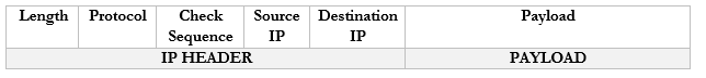
Looking back at the structure of our IP packet, we have a source and destination IP address. The destination will be the broadcast IP.
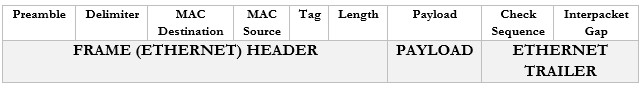
But the computer must send this packet to the switch that it is connected to, so it must put it inside a frame. A frame with a broadcast packet will be called a broadcast frame. The broadcast MAC address is FF:FF:FF:FF:FF:FF. Any frame addressed to this address will be forwarded to all devices in the broadcast domain.
The broadcast domain is all the network devices that will receive a broadcast. That is, all the devices in a subnet make up a broadcast domain.
When the switch receives this broadcast frame, it will notice that the destination MAC address is FF:FF:FF:FF:FF:FF and send it to all the connected devices.
IPv6 does not use broadcasts, only multicast.
You can think of a broadcast packet like some flyers you see in your mailbox. An advertiser will print a pile of them without any addresses and dump them at the post office. The mail man will stick one flyer in every mailbox on his route. The route is the broadcast domain, and the flyer is the broadcast packet.
- Multicast. Both IPv4 and IPv6 use multicast. A multicast message allows a sender to send a message to multiple recipients (but not all the members of a broadcast domain). The sender creates a single multicast packet, but routers and switches replicate that packet and send it to all the required destinations.
On a network, there can be multiple multicast “groups”. Each group has an address. A device that wishes to receive messages addressed to a group sends a “membership report” message to the group’s address, indicating its desire to receive the messages.
Multicast works through the Internet Group Management Protocol. The current version is IGMPv3, which allows a device to leave a group that it previously joined (previous versions only allowed a device to join and not leave).
Who keeps track of the group? The local network router keeps track of the groups and the subscribers. When the local router receives a packet addressed to the group, it sends it to all the subscribers in the group.
You can think of a multicast packet like a newsletter. You must subscribe to the newsletter, but every person who subscribes receives a copy. You can unsubscribe if you want. - Unicast. A unicast packet is one that is addressed to a specific recipient. Most communications are unicast. When a device wants to send a packet via unicast, it puts the IP address of the recipient in the destination.
A unicast packet is like a letter from your friend. It has your address and is sent specifically to you. - Anycast. An anycast packet allows a computer to send a message to one of many recipients. Any anycast group contains more than one recipient. When the router receives a packet addressed to the anycast group, it chooses one recipient from the group and sends the packet to it. The chosen recipient is based on a routing algorithm. The algorithm may choose a recipient that is closest to the sender or use other factors.
Anycast is used in load balancing. For example, if I have multiple servers that perform the same task, I can assign all of them to the same anycast group. I can direct traffic to the anycast group’s address. The router can then decide which server receives each piece of traffic by selecting the closest server.
As we will learn, there are three ways for a device to receive an IP address
- Somebody manually assigns the device a static IP address
- The device automatically receives an IP address from the network through a process known as DHCP
- The device does not receive an IP address and is not programmed with a static IP address. So, it chooses an IP address at random.
Under IPv4, if a device doesn’t have a static IP address and can’t reach a DHCP server, it generates a random IP address in the range of 169.254.0.0 to 169.254.255.255. The process for assigning this address is called link-local address autoconfiguration, auto-IP, or Automatic Private IP Addressing (APIPA). A router will not pass traffic coming from a link-local address.
Under IPv6, every network interface automatically assigns itself a link-local address in the range of fe80::/10, even when it has a routable (static or DHCP) IP address. Link-local addresses are necessary for some IPv6 protocols to function. This is known as a locally unique address because it is possible for devices in other networks to assign the same address. In other words, it will look like the below IP address (where the xxxx’s are unique values).
fe80:0000:0000:0000:xxxx:xxxx:xxxx:xxxx
A link-local IPv4 address is only unique in its own local network, but an IPv6 link-local address is globally unique. Why? A MAC address is considered globally unique (no two devices have the same MAC address). Therefore, if an IPv6 address can be generated from a MAC address, it is also globally unique. The IP address is generated using a process called Extended Unique Identifier 64 (EUI64),
Remember that a MAC address is 48 bits (6 bytes) and follows the format 11:22:33:44:55:66. Like an IP address, a MAC address can be converted into 0’s and 1’s.
The device calculates the new IP address like this
- Let’s say our IPv6 prefix is fe80:0000:0000:0000
- Let’s say our MAC address is 11:22:33:44:55:66
- We split the MAC address in half, and add “fffe” in the middle
- Now our MAC address is 11:22:33:ff:fe:44:55:66
- We flip the seventh bit in the MAC address.
- How can we do that?
- Remember that the MAC address now is 16 characters (or 64 bits) wide. Each octet (separated by a colon) is one byte (8 bits) wide.
- Thus, the number “11” is one byte.
- I can represent the one byte as a combination of eight 0’s and 1’s
- 8-bits makes up one byte. A computer with 8-bits can only count to 255 in one operation. If I make a table that is base-two (every entry is double the previous entry), I can combine these eight numbers to make any number from 0 to 255. Below is my table.
| 128 | 64 | 32 | 16 | 8 | 4 | 2 | 1 |
- If you look at the 8-bits in a byte, each bit is assigned to one of the numbers in my table. If the bit is a one, or in “on’ position, then the number is added to the total, and if the bit is a zero, or in the “off” position, then the bit is ignored.
- In this example, I want to convert the number 11. 8+2+1 = 11. If I write in my table that
| 128 | 64 | 32 | 16 | 8 | 4 | 2 | 1 |
| 0 | 0 | 0 | 0 | 1 | 0 | 1 | 1 |
- Then the resulting binary number is 00001011
- The seventh bit is “1”, so I flip it to “0”
- I rewrite my table to reflect the flip
| 128 | 64 | 32 | 16 | 8 | 4 | 2 | 1 |
| 0 | 0 | 0 | 0 | 1 | 0 | 0 | 1 |
- Now I can recalculate the value as 8+1 = 9
- Thus 11 is replaced by 9 and my new MAC address is 09:22:33:ff:fe:44:55:66
- But wait, there’s more!
- We apply this to our IPv6 prefix, and now our globally unique IP address is fe80:0000:0000:0000:0922:33ff:fe44:5566 (I removed some of the colons from the MAC address portion)
An IPv6 address might look like this 2002:0de8:85c3:0010:0300:8b2e:0360:7234.
We can shorten the IP address. If our IP address looked like this: 2002:0de8:0000:0000:0300:8b2e:0360:7234, we could shorten it to 2002:0de8::300:8b2e:0360:7234. See what we did there? We hid the sections with “0000” and replaced them with ‘::’. In any IPv6 address, we can hide the longest string of 0’s, as long as they fill up an entire segment or as long as a segment starts with 0. We can only hide one string per IP address, otherwise it gets confusing.
If my address looked like this: 2002:0de8:0000:0000:0300:8b2e:0000:7234 and I shortened it to 2002:0de8::8b2e::7234, you now have two “::”, but you don’t know which one had four 0’s and which one had eight.
We can also get rid of any 0’s that are before a “:”. That means 2002:0de8:1824:2383:0300:002e:4e4e:7234 can be shortened to 2002:de8:1824:2383:300:2e:4e4e:7234
Since the IPv6 protocol is still being adopted, not all networks understand it yet. What happens when a router communicating over IPv6 reaches a router that only understands IPv4?
Let’s say that you are trying to access google.com. You’re in Florida and google.com is in California. Your local router understands IPv6, and Google’s router understands IPv6, but the routers in between only understand IPv4.
Your computer and google.com’s server create an IPv4 tunnel and send your IPv6 data through it. The most common tunneling protocol is called 6to4. That is, they package an IPv6 packet inside an IPv4 packet. On the outside, it looks like a normal IPv4 packet, so routers that only understand IPv4 can pass it along, but on the inside, it is an IPv6 packet, so routers that understand IPv6 can read it.
The problem with tunneling is that it reduces the capacity of each packet (we must include additional header data, leaving less room for meaningful data).
A better approach is for each device to obtain both an IPv4 address and an IPv6 address. This is known as dual stack. Most modern ISP’s assign both IPv4 and IPv6 addresses to their customers. A device running dual stack will try to connect over IPv6, and if it can’t then it will try to connect over IPv4.
Remember that when an IPv6 capable device connects to a network, it generates the link-local address automatically? Well, after generating the link-local address, the device sends a message addressed to the IP address it just generated. This message is known as a Neighbor Solicitation and the purpose is to ensure that no other device is using the same address. If another device is using the address, it will reply with a Neighbor Advertisement message. Otherwise, there will be no reply; the device will know that the address is unique and will start using it.
If the address is unique, the device sends a message called a Router Solicitation to ff02::2. All IPv6-enabled routers listen on the ff02::2 address (the long version is ff02:0000:0000:0000:0000:0002). Upon receipt, the router replies with a message called a Router Advertisement. The advertisement contains several pieces of information including
- Whether the router can be used as a default router (default gateway)
- The IPv6 prefix of the link. The prefix allows the device to generate a globally unique IP address.
- The lifetime of the link prefix. The lifetime tells the device how long it can use the IP prefix before generating a new one. This helps with security.
This process is called Stateless Address Autoconfiguration (SLAAC) because each device can configure its own IP address (a router isn’t telling the device what IP address to use). The device will use the process I outlined above (EUI64), but use the prefix provided by the router instead of fe80:0000:0000:0000