
4.2 Secure network components
- Operation of hardware (redundant power, warranty, support)
- Transmission media
- Network Access Control (NAC) devices
- Endpoint security
Redundancy
Redundancy means that there is no single point of failure in our infrastructure. Think about your infrastructure and the components that it consists of. If a single component fails, will the system fail, or does it continue to operate?
How do we make our system redundant? First, we must think about the ways in which it could fail. At the highest level, a natural disaster could take out our entire data center. We can mitigate this risk by building multiple data centers in different locations. We might put them in opposite sides of the same city, opposite sides of the country, or in multiple countries. This is known as geographic dispersal.
Fault Tolerance
Fault Tolerance is the ability of the system to continue operating even when encountering an error. An example of a fault tolerant system is a RAID array. If a single drive in a RAID array fails, the system continues to operate without data loss.
Fault tolerance is expensive, and the organization must weigh the cost of fault tolerance against the cost of not having it (data loss, disruption to its operations, damage to its reputation).
High Availability
High Availability is the state that Fault Tolerance gives us. Fault Tolerance is simply a design goal that results in a system with High Availability.
High Availability means that the system continues to operate even when there is a disruption.
RAID (Redundant Array of Inexpensive Disks (RAID) Levels)
RAID stands for Redundant Array of Independent Disks. It is a feature in a computer server or storage appliance where multiple hard disk drives store the same data.
There are multiple versions of RAID, and each has benefits and drawbacks.
RAID makes the disk storage fault tolerant, but what if we want to take it one step further?
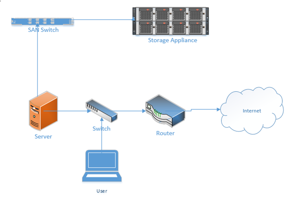
When an organization has lots of data, it is more cost effective to store it on a storage appliance. A storage appliance is basically a server that just stores data. It doesn’t contain expensive processing components. It is also designed to be fault tolerant.
Below is a storage appliance with 24 hard disk drives. We can create multiple shared drives on the storage appliance and then map them to our servers. Then our servers can store their data on this storage appliance just as if it was a physically connected hard disk drive.
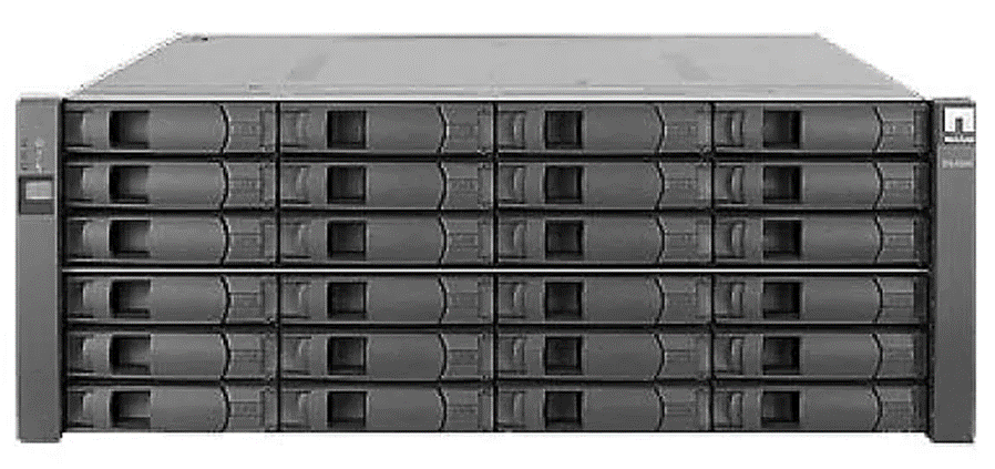
The storage appliance implements RAID by default, but what if the storage appliance fails? We can install multiple storage appliances. We then create a pathway to each one. The server now can store its data in multiple locations. This is known as multipath.
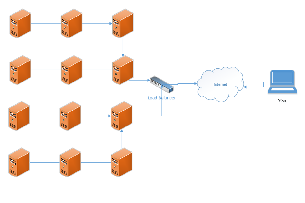
Load Balancer
A load balancer distributes traffic among multiple resources. For example, consider that the Google.com website has only one URL (www.google.com), which would ordinarily point to one IP address. That IP address would ordinarily point to one web server. But one single web server would be overloaded by the traffic; in fact, the Google.com website has millions of web servers. The solution is to install a load balancer in front of those servers. The load balancer can distribute the incoming traffic among all the web servers.
DNS load balancing is when a domain name’s DNS records point to multiple web servers. For example, Google.com’s DNS records could point to both 11.11.11.11 and 12.12.12.12, each of which is assigned to a separate server. This would balance the traffic among two servers (which is not enough for Google). Attempting to balance millions of servers on one DNS record would not work because the customer would not have enough public IP addresses to cover all the servers in use, and the DNS record would be massive.
A load balancer uses a scheduling algorithm to determine how to distribute traffic among the servers connected to it. Consider a scenario where there is one load balancer and three servers, Server A, Server B, and Server C. There are several types of load balancing algorithms
- First Come First Served – each request is handled in the order that it arrives; when the servers are busy then additional requests are put on hold. The load balancer sends the first request to Server A, the second request to Server B, and the third request to Server C. The load balancer does not send additional requests to the servers until a server indicates that it has spare capacity (i.e. that it has completed the current request).
- Round-Robin – each request is handled in the order that it arrives. The load balancer sends the first request to Server A, the second request to Server B, and the third request to Server C. The fourth request is sent to Server A, the fifth request is sent to Server B, and so on. The round-robin algorithm assumes that all the servers have the same capacity, and that all requests are of the same size. If some requests take a server longer to process, they could overload the servers. If one server is more powerful then the rest, it could remain idle for extended periods of time (since all servers receive the same number of requests).
- Weighed Round-Robin – like round robin, but each server is given a specific weight based on its capacity. For example, if server A is twice as powerful as Server B or Server C, it can be given a weight of two, while Servers B and C are each given a weight of one. Server A would then receive twice as many requests as Server B and Server C.
A sticky session allows a load balancer to remember each client (based on their HTTP session). When a returning client is recognized, the load balancer sends that client back to the same server that they were previously connected to, regardless of the server load. This allows the server to maintain the client’s data locally (and not in a central database). This is also known as affinity.
Load balancers typically work in pairs or groups. This prevents the load balancer from becoming a single point of failure.
In a logical network topology, the load balancer is shown to be connected between the internet and the servers that it is balancing. In the physical reality, the load balancer can be connected anywhere on the network. If a load balancer has 1000 servers connected behind it, it wouldn’t have 1000 physical connections to those servers, but instead would route traffic to them over the local network. Regardless of the load balancer’s location, it must have a good network connection, typically 1 Gbps or 10 Gbps.
The group of servers connected to the load balancer can be active-passive or active-active. In an active-active configuration, the load balancer distributes the work among all the connected servers. In an active-passive configuration, some servers remain active (receive work) and some remain passive (do not receive work). In the event of a failure of one of the active servers, a passive server is activated and begins to receive work.
An active-active configuration is better because it can quickly respond to surges in traffic and allows the system to fully utilize all its resources.
In a Virtual IP scenario, the load balancer does not exist. Instead, all the servers work together to share the workload. Consider that we have three servers:
Server A has a private IP of 10.0.0.1
Server B has a private IP of 10.0.0.2
Server C has a private IP of 10.0.0.3
The public IP address is 11.11.11.11
Servers A, B, and C communicate with each other over their private IPs 10.0.0.1, 10.0.0.2, and 10.0.0.3. The servers all set 11.11.11.11 as their public IP, and then elect one server to respond to requests. For example, Server A, B, and C choose to have Server B respond to all requests on 11.11.11.11. If Server B is overloaded, it may communicate this fact with Server A and C (over their private IPs), which designate Server A to temporarily respond to requests on 11.11.11.11.
The servers continually ping each other to ensure that all the servers are functional. This form of communication is known as a heartbeat. If Server B were to stop responding within a specific period, Server A and Server C would choose to designate Server A to respond to new requests.
The algorithm used to determine which server would respond will vary from scenario to scenario.
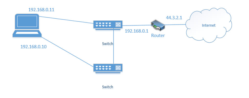
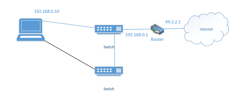
NIC Teaming is a form of load balancing that allows a server to maintain multiple network connections. Remember that a server can have multiple network interfaces. Consider the following server. I have connected it to two switches. Each interface is assigned a different IP address (192.168.0.10 and 192.168.0.11).
You may think that it is fault tolerant because it has two connections. If 192.168.0.11 fails, the server will continue to accept traffic on 192.168.0.11, but this is not fault tolerant because devices connected to the server on 192.168.0.10 will lose their connections. Some clients know to connect to the server through 192.168.0.10 and some know to connect through 192.168.0.11. So, what can we do?
We group the network interfaces into a “team”. We assign the team a single IP address even when the server is connected to multiple switches. This is known as Switch Independent Teaming. One interface is active, and one is passive. The active interface assumes the IP address. When the active interface fails, the passive interface takes over and assumes the IP address.
Right now, the bottom link is active with IP address 192.168.0.10
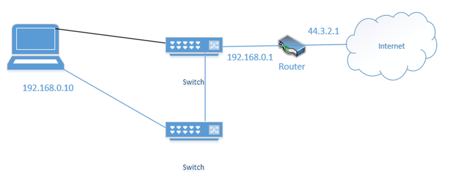
If the bottom link fails, the server assigns 192.168.0.10 to the top link
Below is a setup I have made. On the right, we have two internet connections (one broadband and one cellular). Each internet connection connects to both of the firewalls. Each firewall connects to both routers. Each router connects to both switches. Half of the wireless access points connect to one switch and half connect to the other switch. The switches connect to each other, and the routers connect to each other.
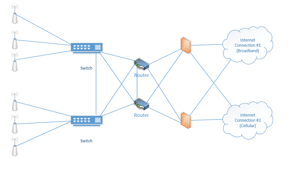
When things are operating normally, the data probably uses the black route. That is, the internet connection #1 is used, the top firewall is used, the top router is used, and both switches are used.
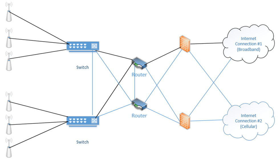
If an internet connection fails, a router fails, and/or a firewall fails, the system will continue to operate. Why? Because we removed many single points of failure.
In my example, we connected each router to both internet connections. One router acts as primary and one router acts as secondary. Remember that every computer on the network has a “default gateway”? That is, if I connect a computer to the switch, how does it know which router to connect to when it wants to access the internet?
We can use the First Hop Redundancy Protocol (FHRP) to create a “virtual router”. We configure FHRP on all the routers. The routers then elect one router to be the primary. The primary router assumes the configuration and becomes the default gateway. If the other routers detect that the primary router has failed, they elect a new router to become the primary. The newly elected router assumes the configuration and becomes the default gateway.
FHRP is a generic idea and can be used to ensure high availability of other services that require a single IP address (such as a web server, DHCP server, e-mail server, etc.). Virtual Router Redundancy Protocol (VRRP) is an FHRP that is proprietary to Cisco devices. Other network equipment manufacturers have their own protocols.
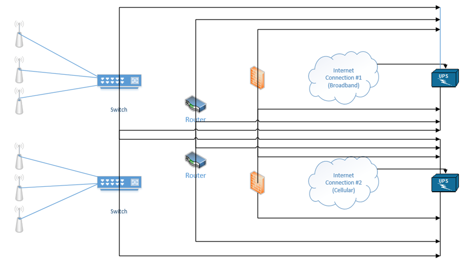
Our devices should each have two power supplies, if possible (the ISP modems usually will not have more than one power supply). We can connect each device to two separate UPSs.
Depending on the size of the building and/or infrastructure, we may have some or all of the following
- Uninterruptible Power Supply (UPS) – Between the electrical supply and our equipment, we install a UPS or Uninterruptable Power Supply. In simple terms, a UPS is a giant battery. We connect our equipment to the UPS, and we connect the UPS to the municipal power supply. If the municipal power supply fails (a blackout) or decreases (a brownout), then the UPS takes over. The UPS must be able to take over so quickly that our equipment doesn’t notice and shut down. A UPS may also protect against power surges (when too much power rushes into the building, which could damage the equipment). When the municipal power supply is active, the UPS charges its batteries. When it fails, the UPS supplies the connected equipment from the battery.
The size of the UPS that we need depends on the quantity and type of equipment that we have. When you purchase electrical equipment, the manufacturer must specify how much power it consumes (in Watts). A Watt is a unit of energy consumption. Equipment may use more power when it is busy than when it is idle. Therefore, we should calculate the maximum power consumption of all our equipment.
A UPS is rated in Watts. We should not exceed the Wattage rating of the UPS. We should consider purchasing a UPS that can handle 20% to 50% more capacity than we are consuming, in case we need to add new equipment in the future. Also, no UPS is 100% efficient.
The second factor we should consider is the runtime. The runtime tells us how long the UPS can power our equipment for. We should think about how much time we need to properly shut down our equipment. If shutting down the equipment is not an option, then we should think about how much time we need until our power generator takes over.
A UPS can be a small unit that sits on a shelf, a rack-mounted unit, a unit that is the size of a rack, or an independent unit.
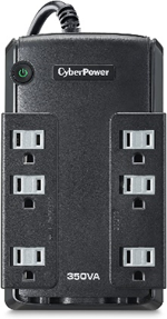
This is a small UPS. It might sit on the floor under your desk. It is good for powering a single device or a few small devices. It costs approximately $50. If we have a single switch or router, or an important computer, this might be acceptable.
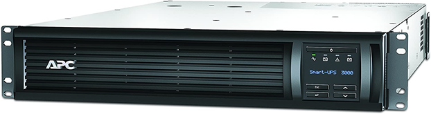
This is a rack-mount UPS. It takes up 2Us in a rack and is good for powering a rack full of devices. It costs approximately $2000. If we have a single rack full of equipment, this might be acceptable. It would be a good idea to purchase two separate UPSs for redundancy.
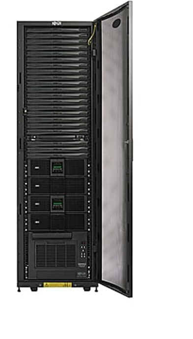
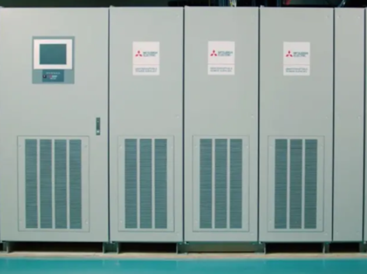
This is a full rack UPS. It comes as a full rack and can sit in an MDF or IDF. If we have multiple racks full of equipment, this might be a better solution than using multiple 2U UPSs.
This UPS requires an electrician to install. Equipment will not connect directly to this UPS. Instead, this UPS is connected to an electrical panel. From the electrical panel, we install multiple electrical circuits. We then connect our equipment to the electrical circuits.
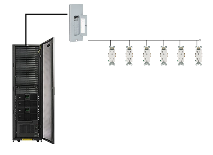
UPSs can be much larger. A large building such as a school, shopping mall, or hospital may have a UPS that is connected to the electrical panel and electrical outlets.
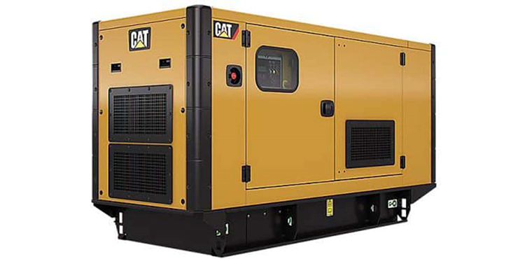
- Generator – What if we have a power outage that lasts three days and we need to keep operating, but our UPS only lasts one hour? We install a power generator, which is a device that can produce electricity. When the power outage takes place, the UPS supplies power from its batteries, and the generator produces new power to recharge those batteries.
A typical power generator burns diesel. Generators can be portable or fixed. It is better to have a power generator and not need it then to need it and not have it. The power generator should be maintained regularly to ensure that it is operating and that it contains an adequate supply of fuel. The organization should also make sure that it has a contract to receive additional fuel deliveries during a long power outage.
If we don’t have a UPS, the power generator can feed power directly to the building’s electrical distribution. This isn’t a good idea because if the generator fails or takes time to start up, then our systems will stop operating.
The generator requires regular maintenance and testing.
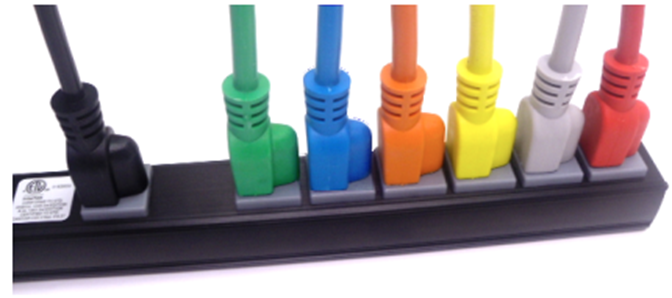
- Power Distribution Units (PDUs) – Finally, to avoid any single point of failure, it is important to select network devices and servers with redundant power supplies. If we have two UPSs, we connect one power cord from each device to the first UPS, and we connect the second power cord to the second UPS. That way, if a UPS fails, the devices continue to receive power. Most devices with dual power supplies offer power supplies that are hot swappable. Electronics use power that is DC (Direct Current), while a UPS or municipal power supply provides power in AC (Alternating Current). An electronic device will contain an adapter that converts from AC to DC. This adapter may fail during operation. When it is hot swappable, it can be replaced even while the device is powered on.
In a data center with hundreds of devices, it can become difficult to identify which plug goes to which power supply. As a result, manufacturers produce power cables in different colors such as red, green, and yellow. You can use these cables to tell different circuits apart. You can also use them to color code different types of devices such as routers, switches, firewalls, etc..
A Managed PDU can be connected to our network. Some features of a managed PDU - We can remotely activate or deactivate an outlet. This allows us to remotely reboot a connected device that is not responding.
- We can determine whether an outlet is functioning, and how much power it is drawing.
Replication
I mentioned storage appliances earlier. A Storage Area Network uses some of the same principles as an ethernet network. A server might connect to both a normal ethernet network (for communicating with users) and a storage area network (for communicating with the storage appliances).
Some concepts
- A Host Bus Adapter or HBA is like a network interface card. It connects the server to the storage area network. The HBA operates on the first layer, known as the Host Layer.
- A SAN Switch is like an ethernet switch, but it forwards traffic between devices on the storage are network
- We call the SAN network devices (switches, routers, and cables) the fabric
- Each device in the SAN has a hardcoded World-Wide Name (WWN) which is like a MAC address in the ethernet world. The switch uses the WWN to route traffic between devices. The switch operates on the second layer, known as the Fabric Layer.
- Switches and HBAs don’t understand what files are. They only see data moving as “blocks”, or groups of 0’s and 1’s.
- SAN networks can operate over copper or fiber links
- The third layer is known as the Storage Layer.
- Each storage appliance is assigned a unique LUN or Logical Unit Number. A storage appliance is a box of hard disk drives. We can subdivide a storage appliance into multiple partitions and assign each partition a unique LUN.
- Each server (or device that can read from or write to a storage appliance) is assigned a LUN.
- We can use the LUN to restrict access from specific servers to specific storage locations. The storage appliance maintains an access control list, which determines (on a LUN by LUN basis) which devices can access each of the storage appliance’s LUNs.
There are many network protocols that can be used for communicating over a SAN
- FCoE or Fiber Channel over Ethernet
- Fiber Channel Protocol
- iSCSI
- SCSI RDMA Protocol
The SAN does not provide “file level” storage, only “block level” storage. That is, a server can’t call up the storage appliance and say something like “give me the file called DraftProposal.docx”, because the storage appliance doesn’t know what files are.
Instead, SAN says to the server, “here is a bunch of storage space, do what you want with it”. The server says, “here is a bunch of data in the form of 0’s and 1’s, put them there, there, and there”. The server must be able to manage the file system. When a user asks the server for the file DraftProposal.docx, the server asks itself “where did I put DraftProposal.docx…oh yeah…I put there, there, and there?”. The server treats the storage appliance like its own giant hard drive. It may create a file allocation table on the storage appliance to help itself find files.
The Storage Appliance keeps the files safe. It uses RAID and proprietary technologies to ensure that it provides an adequate level of redundancy. If we have multiple data centers or multiple locations, we can build a SAN in each location and have them replicate the data constantly. That ensures that each data center has a copy of the data. If something happens to one data center, we can receive our data from the other center.
If our servers are virtualized, we can take this one step further. We can put physical servers in both data centers, and replicate our virtual machines across both of them.
One system that provides High Availability in a server environment is VMware VSphere – Fault Tolerance. VSphere is a hypervisor that allows a user to create multiple virtual servers on a physical machine. High Availability by VMware distributes the virtual server workload on multiple physical machines, which can be in different geographic locations. In the event of a failure of a server component, or even a physical server, the system continues to operate as normal. VMware also provides a system called High Availability.
In a less-complicated environment, we could use a NAS or Network Attached Storage device. Like a storage appliance, a NAS is a box of hard disk drives. But unlike a storage appliance, a NAS connects to the ethernet and provides file level storage. A NAS is more like a server that can store data (and does nothing else).
Some protocols that can be used with a NAS
- Apple File System
- Network File System
- FTP
- HTTP
- SFTP
- Server Message Block
Let’s dig deeper into the storage appliance’s connections.
If we didn’t want to build out a separate storage area network, we could use FCoE or Fiber Channel over Ethernet to transmit all our storage data on our existing ethernet network.
FCoE uses 10 Gbit Ethernet to communicate. Just like ethernet, fiber channel uses frames to communicate. When transmitted over FCoE, each fiber channel frame is encapsulated (packaged) inside an ethernet frame, transmitted to the recipient, and then deencapsulated by the recipient.
Each device connected to an ethernet network must have its fiber channel name mapped to a unique MAC address, so that the ethernet network knows where to deliver the data. This can be completed by a converged network adapter or CNA. A CNA is a device that contains a host bus adapter and an ethernet adapter.
A Fiber Channel network communicates between 1 Gbit/s and 128 Gbit/s via the Fiber Channel Protocol. We can create the following types of connections
- Point-to-Point: two devices communicate with each other through a direct cable connection
- Arbitrated Loop: devices are connected in a loop. The failure of a single device or link will cause all devices in the loop to stop communicating. This connection type is no longer used.
- Switched Fabric: devices are connected to a SAN switch. The fabric works like an ethernet network and can scale to tens of thousands of devices.
There are five layers in fiber channel
- The Physical Layer (Layer 0), which includes the physical connections
- The Coding Layer (Layer 1), which includes the transmission/creation of signals
- The Protocol Layer, known as the fabric (Layer 2), which transmits the data frames
- The Common Services Layer (Layer 3), which is not currently used but can be used for RAID or encryption if the protocol is further developed
- The Protocol Mapping Layer (Layer 4), which is used by protocols such as NVMe and SCSI
We use SFPs, SFP+s, and QSFPs with fiber optic cables to connect the various devices in a Fiber Channel network.
iSCSI or Internet Small Computer Systems Interface is another network protocol that allows storage devices and servers to communicate. iSCSI operates over the existing ethernet network without the need for special cabling or adapters. We typically use iSCSI for two purposes
- Centralize our data storage to one or several storage appliances
- Mirror an entire data storage appliance to an appliance in another location to protect in the event of a disaster
The different iSCSI devices
- Initiator. An initiator is a client device such as a computer or server. A software application or driver sends commands over the device’s ethernet adapter in the iSCSI format. For faster communications, a hardware iSCSI host bus adapter can be used.
- Target. A target is a storage device such as a server or storage appliance. A device can be both an initiator and a target.
- Like Fiber Channel, each device is given a LUN or Logical Unit Number.
Some features of iSCSI
- Network Booting. A device can boot from a network operating system and then access an iSCSI target to store and retrieve its data. When the computer boots, instead of looking at its hard disk for the operating system, it contacts a DHCP server that contains a boot image of an operating system. The DHCP server uses the device’s MAC address to forward it to the correct iSCSI device. The iSCSI drive is then mounted to the computer as a local drive.
- iSCSI uses ports 860 and 3260
Security Problems
- iSCSI devices authenticate via CHAP by default but can use other protocols. CHAP is not secure. We will learn more about CHAP later.
- iSCSI devices can be connected over a VLAN so that they are logically isolated from unauthorized users or devices. If we automatically trust all the devices on the VLAN, then a compromised device can gain access to the entire system.
- iSCSI devices can be connected over a separate physical network. If we trust all devices on the physical network, then a compromised device can gain access to the entire system.
- An eavesdropper can spy on the data being transferred over the iSCSI network if the data is not encrypted (and it frequently isn’t).
InfiniBand is another storage area network connection format. InfiniBand is typically used by supercomputers that need a very high level of data transfer and a low latency. It can support transfer rates of up to 3000 Gbit/s. It uses QSFP connectors and copper or fiber cables.
We can also transfer Ethernet over an InfiniBand network.
Backup Types
A backup utility backs up data. The utility could be set to operate automatically or manually. The utility may back data from a server, computer, network video recorder or other device. The back-ups can be stored on a storage appliance, tape, removable drive, or in the cloud.
It is important to back up data regularly. A large organization may have an individual or group dedicated to maintaining back ups.
- Back up all data regularly (incremental and full back ups)
- Verify that the data has been backed up
- Retain a copy of the backed-up data on site and retain a copy off site (in case of a natural disaster)
When planning a back-up strategy, think about whether it allows the organization to resume normal operations, and how quickly. The speed of the recovery should be weighed against the cost of the back-up strategy. Disaster recovery is discussed in more depth further on.
There are four main types of back ups: Full, Differential, Incremental, and Snapshots. The type of back up affects the way that data is backed up and the way that data is restored.
A Full backup is a backup of the entire set of data. The first time a back up is performed, a full back up must be performed. An organization may perform a full back up once per week or once per month. A Bare Metal back up is a full backup of a logical drive, which includes the server operating system. A Bare Metal back up can be used to restore the server’s operating system and applications, whereas a normal full back up may contain only user-generated data.
A Differential Backup is a backup of the data that has changed since the last full backup. The organization must be careful to ensure that it is able to accurately keep track of data that has changed.
An Incremental Backup is a backup of the data that has changed since the last Full Backup or Incremental Backup. Why use Incremental or Differential backups? Which is better? How does it work?
Consider an organization that performs Full and Differential backups. If the organization performed
- A full back up on Monday (all the data is backed up)
- A differential back up on Tuesday (the data that was changed between Monday and Tuesday is backed up)
- A differential back up on Wednesday (the data that was changed between Monday and Wednesday is backed up)
- A differential back up on Thursday (the data that was changed between Monday and Thursday is backed up)
- A differential back up on Friday (the data that was changed between Monday and Friday is backed up)
Consider an organization that performs Full and Incremental backups. If the organization performed
- A full back up on Monday (all the data is backed up)
- An incremental back up on Tuesday (the data that was changed between Monday and Tuesday is backed up)
- An incremental back up on Wednesday (the data that was changed between Tuesday and Wednesday is backed up)
- An incremental back up on Thursday (the data that was changed between Wednesday and Thursday is backed up)
- An incremental back up on Friday (the data that was changed between Thursday and Friday is backed up)
An incremental backup generates less data than a differential backup, but it is faster to restore data from a differential backup. If the organization uses differential backups and experiences data loss on Thursday
- It must restore the data that from Monday’s full back up
- Then it must restore the data from Thursday’s differential back up
If the organization uses incremental backups and experiences data loss on Thursday
- It must restore the data that from Monday’s full back up
- Then it must restore the data from Tuesday’s incremental back up
- Then it must restore the data from Wednesday’s incremental back up
- Then it must restore the data from Thursday’s incremental back up
Notice that in every process, the full backup must first be restored. In the case of a differential backup, the most recent differential backup must then be restored. In the event of an incremental backup, all the incremental backups created after the full backup must be restored. An incremental backup takes less time to create than a differential backup but takes longer to restore.
If the organization creates a full backup each week, then the organization would (at most) restore six incremental backups. If the organization creates a full backup each month, then they would have to restore up to thirty incremental backups.
Why use a combination of full and incremental back ups? Why not perform a full back up every day? A full back up may take a long time to run and take up a large amount of space. What if the full back up takes 28 hours to run – then we can’t create a full back up every day?
What if the organization maintains 10,000TB of data, but only changes approximately 100TB per week? Should the organization generate 70,000TB of data back ups every week? If the back up location is in the cloud, then the organization will need to pay for 70,000TB of storage and bandwidth each week.
A snapshot is an image of a virtual machine or a disk. A snapshot allows an organization to restore a server or application to a previous state in the event of a hardware failure or corruption of the software. The benefits of a snapshot
- A server can be restored to an exact state, which could include its operating system, applications, configuration, and data.
- It would otherwise take hours or days to restore a server to its original state, especially if the application installers are no longer available, or if the installation process was not documented
- If a user makes changes to the system that cause damage or undesired operation, the system can be restored to a working state
It may not always be possible to take a snapshot. A hypervisor can take a snapshot of a live virtualized system while it is running, but it may not be possible to image a physical system without shutting it down (which could affect operations).
How often does an organization need to perform a back up? The organization must weigh the cost of the back up against the cost of the potential data loss, and the time that it will take to restore the data.
- If the back up is performed daily, the organization could risk losing a day’s worth of data.
- If the back up is performed weekly (say on a Monday), and data loss occurs on a Friday, the organization could lose all the data generated between Monday and Friday.
- If the back up is performed in real time (i.e. replicated to another site), then the organization will not lose any data, but replication is expensive.
We don’t need to have the same back up strategy for the entire organization. Some data may be more valuable than others. We can also archive old data that we maintain for historical purposes but don’t access or don’t access often.
What are all the methods that we can use to back up our data?
- Cloud. There are many services including Amazon S3 and Amazon Glacier. Back ups can be configured automatically.
- Replication over SAN (Storage Area Network). When having multiple locations, the SAN can replicate the data to each location. This is good for massive volumes of data.
- NAS (Network Attached Storage). This is good for medium sized volumes of data (up to 10 TB)
- Tape Library. A tape library is a system that automatically backs up the data onto magnetic tapes. We can insert new tapes and eject back up tapes to store them in an off-site location. Tape libraries range in size. This can be good for medium to large volumes of data.
- Disk Cartridge. A disk cartridge is like a removable hard drive that you can store. Disk cartridge back ups are good for small volumes of data.
- Removable Disk (USB Drive). You can connect a USB drive and back up the data manually
We should look at the following for each type of data
- How much money will the organization lose if it is lost?
- How much time (in hours or days) can the organization wait before having the data restored?
- What is the volume of data to be backed up?
- Based on this information
- We know how much we can afford to spend on the data back up
- We know how much data needs to be backed up in GB or TB or PB
- We know how quickly we need to restore our data. The time to restore the data is the time to bring the data back up to the facility and the time to complete the restoration process.
- If the back up is in the cloud, then we can figure out the bandwidth we require
- If the back up is at a storage vendor, then we can figure out the maximum distance of the storage location
- We can figure out how often to run the back up and whether we can use incremental or differential back ups
- We can decide whether the back up is online or offline. An online back up is one that is physically or logically connected to the system. An offline back up is one that is on a storage medium such as a magnetic tape, or a hard disk cartridge.
It is usually faster to restore data from an online system because the data is already accessible. We just need to copy it. The offline back up must be physically connected to the system and then copied. If it is offsite, then it must first be brought to site, and then connected.
- If the back up is in the cloud, then we can figure out the bandwidth we require
- We know how much we can afford to spend on the data back up
- What is the organization’s risk appetite?
- The question is, does the organization like to spend money to avoid risks?
- If the organization has a high-risk appetite, then they may not want to spend the money on multiple back ups.
- A common strategy is called 3-2-1. – we have three copies of the data, and two types of media, with one off site. What you should do
- One copy in production (this is the live data)
- Two copies in the cloud, each in a separate region
- Two physical copies as back up. Each one should be a separate type of medium.
- If we use a SAN with physical replication, then that might be considered the off-site physical copy
- If not, then one copy might be on a tape and the second might be on a hard disk drive
- If we use a SAN with physical replication, then that might be considered the off-site physical copy
- One physical copy should be stored on site and one physical copy should be stored off site (either at another office or at a vendor like Iron Mountain)
- One copy in production (this is the live data)
- The question is, does the organization like to spend money to avoid risks?
Non-Persistence
Non-Persistence is a concept where changes to a system are not permanent. If somebody makes a change to a system that causes harm, it can be returned to its previous working state.
- Snapshots. A snapshot is an image (a replica) of a system at a point in time. If a system fails due to a change in its configuration, it can be reverted to the time when the snapshot was created. Snapshots are more common with Virtual Machines.
- Data created between when the snapshot is created and when it is used will be lost. User data such as documents can be stored in a separate volume and protected with backups and the Volume Shadow Copy so that they are not affected by snapshots.
- Data created between when the snapshot is created and when it is used will be lost. User data such as documents can be stored in a separate volume and protected with backups and the Volume Shadow Copy so that they are not affected by snapshots.
- Revert to Known State. Reverting to a point in time when the configuration was good.
- An example of this feature is Windows Restore, which regularly creates internal “snapshots” each time an important update is installed. These are known as “restore points”. A user can restore his computer back to a time when the restore point was created. Windows Restore preserves user data such as documents and photographs
- Applications can automatically create system restore points when they are installed.
- An administrator can disable Windows Restore in an enterprise setting.
- An example of this feature is Windows Restore, which regularly creates internal “snapshots” each time an important update is installed. These are known as “restore points”. A user can restore his computer back to a time when the restore point was created. Windows Restore preserves user data such as documents and photographs
- Rollback to Known Configuration (Last Known Good Configuration). This is a Windows feature, also known as the “last known good configuration”.
- When run, Windows restores the registry to a previous version. Applications and user files are preserved.
- This tool is not always effective because while most configurations are stored in the registry, many are stored in INI files.
- This feature was removed in Windows 8
- When run, Windows restores the registry to a previous version. Applications and user files are preserved.
- Live Boot Media. A live boot medium could be a network boot source (PXE boot) or a bootable USB drive. These systems may be able to back up user data, reimage the computer, and the reload the backed-up data.
- Using Live Boot Media is a last resort when other methods have not worked.
.
Restoration Order
What do we restore first? Second? Last? The organization must rank each system based on how critical it is for the organization’s goals. Factors include
- Is the system critical for life safety such as a fire alarm, security system, electrical generator, etc.?
- Do other systems interconnect with or rely on this system? For example, the organization cannot restore any servers until the power is first restored.
- How profitable is each system? Systems belonging to profitable business units should be restored first.
- What is the demand for each system? Systems belonging to business units that provide high-demand products or services should be restored first.
Order of Restoration commonly applies to data loss. Copying data from a physical back up to a production system represents a bottleneck. It may take hours (or days or weeks) to copy all the data. During the back up process, the organization must separate the data based on its criticality, so that more important data can be identified and copied first during the restore process.
If all the data was stored as a “blob” in the back up, then it would be impossible to restore critical data first.
Diversity
Vendor Diversity is a practice of using multiple vendors for network devices. For example, using a Fortinet firewall with a Cisco router and a Juniper switch. If a security hole affects multiple classes of devices manufactured by the same vendor, then the entire chain of devices will not be affected.
Another form of vendor diversity is to use multiple devices made by multiple vendors. For example, an organization can install two firewalls (one Fortinet and one Juniper) between their internet connection and the internal network. This may be more expensive to implement and maintain, but the possibility that both firewalls suffer from the same security vulnerability is low.
Technology Diversity is a practice of having multiple types of technology for a critical function. If a flaw is discovered in one form of technology, then we have a second form that is functional. For example, if we have a vault, we might put two types of motion sensors inside it.
Control Diversity is a practice of having multiple layers of security. Administrative diversity involves having multiple security policies and standard operating procedures. Administrative controls are rules and regulations that deter or prohibit specific activities. Technical diversity involves using software or hardware to prevent security violations.
User Training involves educating individuals to prevent security threats. Teaching people to recognize security threats that cannot be detected by technological measures (such as social engineering) is important. User training adds another layer of security.
The possibility that a threat penetrates a single layer of security might be high, but the possibility that it penetrates multiple layers of security is much lower.
Crypto Diversity means using multiple types of cryptography algorithms. If one type of algorithm is proven to be flawed, our data can still be secured by the other one. For crypto diversity to work, we need to encrypt our data twice – once with each algorithm.
End of Life (EOL). A product’s End of Life is when the manufacturer stops manufacturing the product. The manufacturer might announce the EOL well in advance or might do so abruptly. We do not want to buy a product that will become obsolete.
- What is the EOL date, if announced, or when do we anticipate an EOL?
- Will the manufacturer replace the product with a similar product?
- Do other vendors make a similar product?
- Will the manufacturer continue to support the product (warranty, repairs, patches, support, etc.)?
- Can we still purchase OEM or aftermarket parts for the product?
- Is it cost-effective to stockpile the product for further use?
For example, if you were buying a specific model of Cisco switch and Cisco decided that they were going to stop manufacturing it, you would expect the following
- Cisco will announce the EOL data a year in advance
- Cisco will continue to make patches / IOS updates for the switch
- You can still obtain a replacement switch if yours fails under warranty
- Cisco will make a newer model switch to replace the one that has reached the EOL
- You can buy switches from other vendors such as HP, Juniper, etc., which might work well as replacements for the Cisco switches. But you probably don’t want to mix and match switch vendors.
End of Service Life (EOSL). A product’s End of Service Life is when the manufacturer stops supporting it. This is generally a few years after the EOL, and no earlier than when the warranty on the last device sold has expired.
That means that we don’t have any more support from the manufacturer, warranty repairs, or patches. We don’t want to buy a product that has reached its EOSL.
If we have a device in use that is approaching its EOSL then we want to create a plan for replacing it before the EOSL has arrived. We want to have enough time to evaluate the available replacement devices, install them, configure them, test them, and work out any issues so that we are not stuck.
In some cases, we might not have an available replacement device, such as in the case of a legacy system. We might not have any choice but to keep using it. We might try to obtain service from an independent repair shop, or we might try to obtain maintenance documentation from the manufacturer.
One question we should ask is whether the software we use will run on the replacement hardware, or whether the hardware we use will run the replacement software.
Now we have an idea of how our network will work, we can look at the types of cables we can use to connect it. There are two main choices: copper or fiber.
There are two types of network cable: Copper and Fiber. When do we use copper and when do we use fiber?
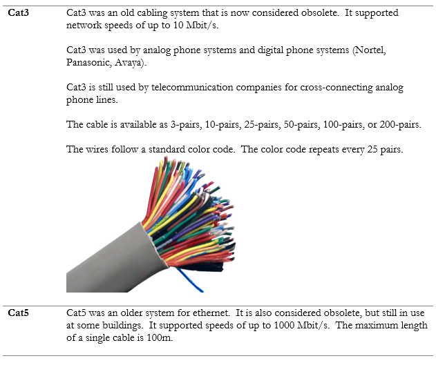
Most of the copper wiring in use is Unshielded Twisted Pair (UTP). This is a standard ethernet cable that contains eight wires, twisted into four pairs. The twists are designed to cancel out most forms of electromagnetic interference (from radio waves and nearby power lines). UTP can be run up to 100 meters.
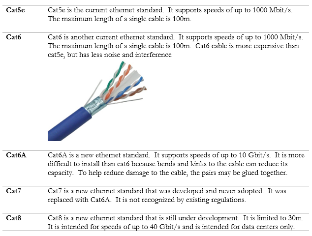
For more advanced applications, we can use a Shielded Twisted Pair (STP) cable. This is also known as F/UTP cable. The difference is that the STP cable contains a foil around the wires. The foil blocks out even more electromagnetic interference than the twists. The foil connects to the termination point on each end of the cable and acts as an electrical ground. STP cable is used in applications such as video transmission and in areas where there is a large amount of interference. If we peel back a cable, we can see the difference.
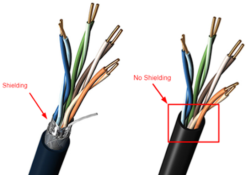
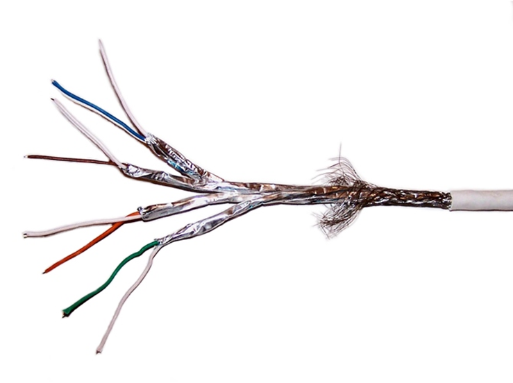
If we went crazy, we could buy a cable that had a separate shield around every pair. The shield protects the wires from electromagnetic interference. It also protects individual wire pairs from cross-talk (interference from a neighboring wire pair).
Most device network interfaces accept a copper (UTP or STP) connection. That includes switches, IP cameras, computers, and VoIP phones.
Another form of copper wiring is coaxial. Coaxial wiring can be run up to 500 meters. It consists of a central conductor with a braid wrapped around it. The braid shields the central conductor from electromagnetic interference that could disrupt the signal.
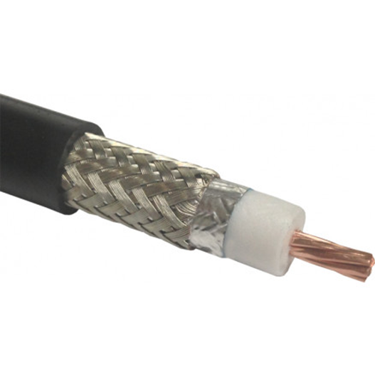
Coaxial cable can be run up to 500 meters. It is used to connect older analog cameras, satellite systems, antennas, and cable modems.
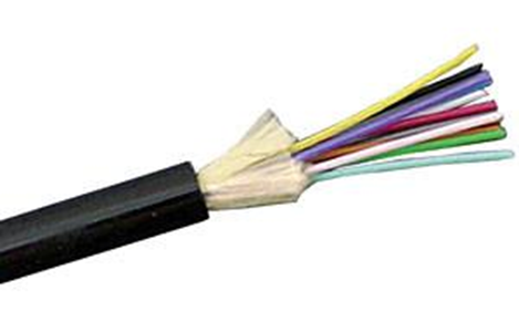
Fiber optic cable can be run longer distances than copper. It also has a larger bandwidth. But fiber is more difficult to install than copper. It requires specialized equipment to test and terminate. A fiber optic cable uses light to transmit data.
We can’t connect a fiber optic cable to standard host devices. For example, a VoIP phone or computer will not have a fiber optic connector. If we ran a fiber optic cable to a far away computer, we would need a device called a media converter to convert the fiber to copper.
Fiber comes in two forms: single-mode, and multimode. Single mode cable can be run upwards of 200 km. The light signal travels down the center of the cable as a single signal. Multimode cable can be run up to 1 km. The light bounces up and down inside the cable.
A single copper cable contains eight wires. When connected, the copper cable carries data in multiple directions. But a single fiber optic cable can contain multiple strands. A single strand carries data in only one direction. When we peel back the fiber optic cable, we find multiple strands, which can be color coded. We need at least two strands to make a circuit and carry data. Most common sized fibers have six or twelve strands.
Some of the most common copper standards are outlined in the table below.
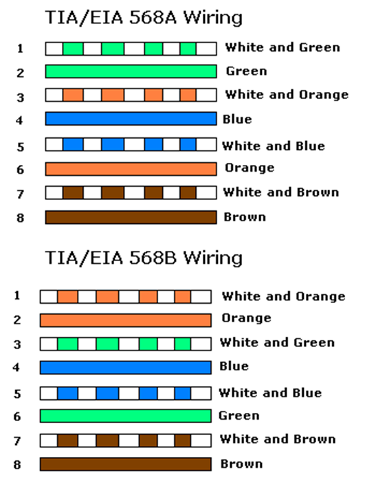
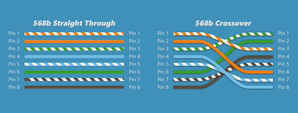
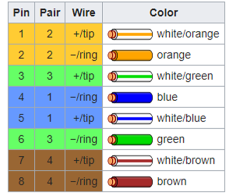
There are two methods for terminating a cat5e/cat6/cat6A cable. The methods are known as 568A and 568B. Remember that the ethernet cables contain 4 pairs of wires (colored as blue, orange, green, brown). The difference between 568A and 568B is that the position of the orange and green wires is swapped.
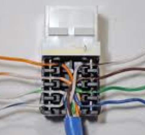
If we look at the side of a cat5e jack, we can see that the manufacturer has marked a color code for “A” style terminations and “B” style terminations. On the other side of the jack, we would see similar markings. The color order may vary from manufacturer to manufacturer.
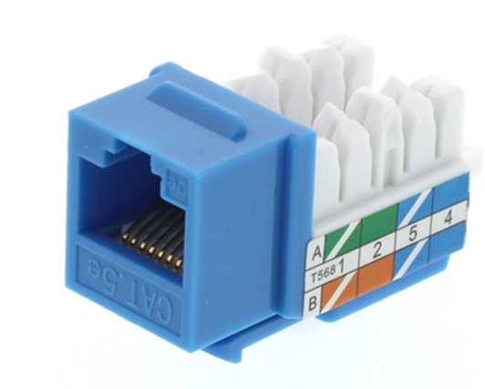
We should insert the wire into the correct colored slot on the jack or patch panel and then terminate it with a punch-down tool of the appropriate size.
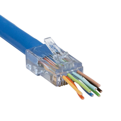
We could also terminate the cable to a male connector. The male connectors follow the same color code as the female connectors. We use a tool called a crimper to secure the wires inside the connector.
Both 568A and 568B are acceptable termination methods. A cable should be terminated with the same method on both sides. An organization may require the cable to be terminated using a specific method. Most organizations prefer 568B, and most governments prefer 568A.
If we terminate the cable in the same order on both ends, we call it a straight through cable. If we terminate the cable as 568A on one end and 568B on the other end, the orange and green pairs become crossed. This is called a crossover cable.
Why would we make a cross-over cable? Network devices usually use the orange and green pairs to communicate. A device like a switch transmits over the orange pair and listens on the green pair. A device like a computer transmits on the green pair and listens on the orange pair. If we connect a computer to a switch, collisions do not take place.
If we want to connect two computers together or two switches together, they will try to talk on the same pair and listen on the same pair. No data will get through. The device doesn’t know the color of the wire; it only knows the position of the wire. If you punched the blue wire in the orange wire’s spot, the device would communicate over the blue wire.
So, if we use a cross-over cable, then one switch will transmit over the orange pair (wires 1 and 2) and listen over the green pair (wires 3 and 6). The other switch will transmit over the green pair (wires 3 and 6) and listen over the orange pair (wires 1 and 2).
We don’t need crossover cables to connect switches anymore. If two modern switches are connected via a straight through cable, they will immediately detect the collision and agree on who will use which wire pairs.
The coaxial cable is available in many sizes. The number relates to the thickness of the core conductor in the center. The two most common RG-59 and RG-6. Coaxial cable is used for satellite systems, surveillance cameras, cable modems, and other analog systems. Your ISP may install it, but I do not recommend it unless absolutely required.
| RG-59 | RG-59 is used for short lengths and is cheaper than RG-6. |
| RG-6 | RG-6 is used for satellite systems and surveillance cameras. It can provide a better-quality signal than RG-59 |
Twinaxial cable or Twinax is a coaxial cable with two internal conductors. Twinax can be used for 10GB or 40GB Ethernet. A 100GB version is being developed. The maximum length of a Twinax is 10 meters. Twinax is being used to connect servers, switches, and storage appliances in data centers, where a high bandwidth, low latency connection is required.
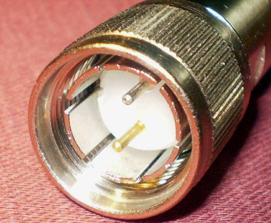
After we install the cable, we must terminate it somehow. We must put a connector on the end so that we can plug it into something. A copper connector can be male or female.
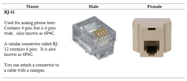
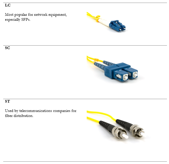
We also have connectors for fiber optic cables. We can purchase adapters for any type of fiber connector. Notice that fiber cables do not have female connectors, only male. We can convert a male connector to a female connector by connecting it to a coupler.
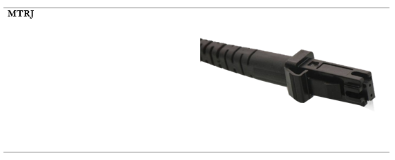
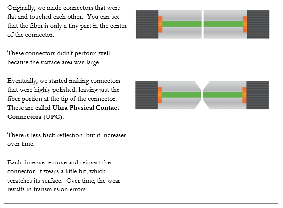
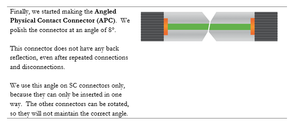
After a fiber connector is manufactured, it is polished. The angle at which it is polished affects its data transmission. Two fiber connectors must be mated together so that they can transmit data.
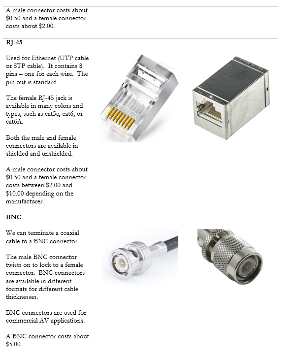
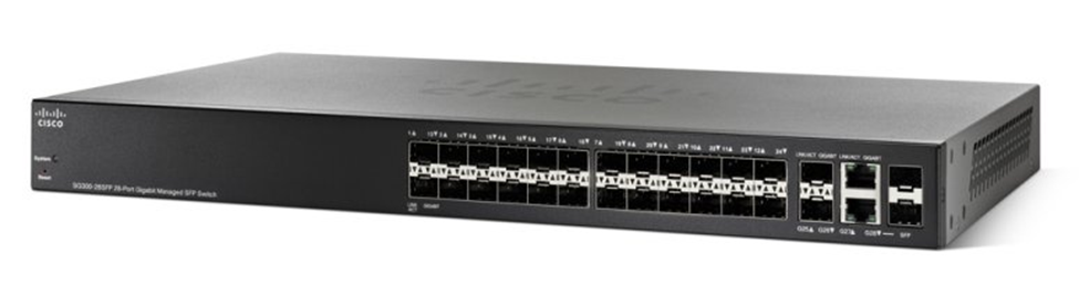
Look at this Cisco switch. On the left are 48 copper ports. Each one can accept a single RJ-45-terminated cable. On the right are four additional ports – the bottom two are copper and the top two are “SFP”, or small form-factor pluggable transceiver.
You can’t plug a cable into an SFP port.
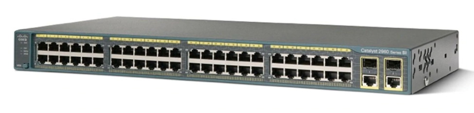
So, what’s the point? Well, there are many types of cables and available speeds – copper, single-mode fiber, multi-mode fiber, 10Gbit speeds, 1Gbit speeds, etc. The manufacturer of the switch can’t sell a different type of switch for every possible connector. It would result in too many switch combinations. Instead, the manufacturer adds some “SFP” ports.
Look at this switch. Almost all its ports are SFP ports.
You figure out what kind of connections you require – copper or fiber (single-mode or multi-mode). And you decide the speed that you require – 1GB, 10GB, or 40GB. And if you’re using fiber, you decide what kind of connector you’re using LC, SC, etc.. Then you buy the right SFPs and insert them into the switch. An SFP could cost between $10 and $2000 depending on the speed and cable types. You can mix and match SFPs on a single switch.
An example of a copper SFP is below. You insert the SFP into an SFP port and then you insert the cable into the SFP. SFPs are hot-swappable (that means we can change the SFP while the switch is running and the switch will recognize the new SFP).
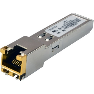
The maximum speed of an SFP is 1 Gbit/s, but the maximum speed of an SFP+ is 10Gbit/s. It is also known as an enhanced small form-factor pluggable transceiver. An SFP+ works with fiber and copper connectors.
For even faster speeds, such as those required in the networks of major Internet Service Providers, the QSFP or Quad Small Form-factor Pluggable transceiver can be used. The QSFP can provide speeds of up to 4 Gbit/s.
For even faster speeds, now there is the QSFP+, which provides speeds of up to 40 Gbit/s. There is also the QSFP14, which provides speeds of up to 50 Gbit/s, the QSFP28, which provides speeds of up to 100 Gbit/s, and the QSFP56, which provides speeds of up to 200 Gbit/s.
Below is an example of a fiber SFP. You will notice that it has space for two fibers. That is because a single stand of fiber typically operates in one direction at a time, whereas an ethernet cable operates in both directions at the same time. Thus, we would need two fiber strands to complete a “circuit”.
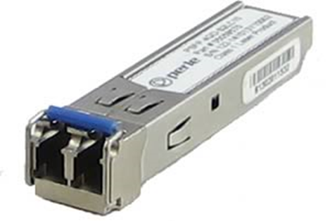
Some service providers use a bidirectional fiber, which allows the signal to travel in both directions at the same time. Each direction transmits a signal in a different wavelength. For example, we might transmit in 1310 nm and receive in 1550 nm. A bidirectional fiber allows a service provider to conserve their fiber resources when they are scarce.
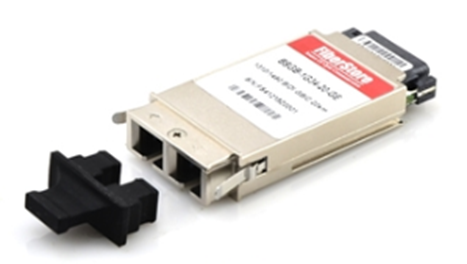
Before SFPs we had GBIC (Gigabit Ethernet and Fibre Channel) transceivers, but they were much larger. They only operated at rates of up to 1 Gbit/s.
A common termination point for an ethernet cable is a patch panel. These panels are commonly available in 24-port and 48-port sizes. The panel fits into a standard network rack. Wall-mounted panels are also available.
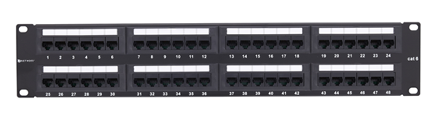
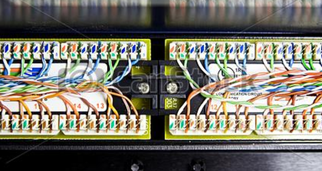
At the back of the panel are spaces to insert each wire. We should peel the STP or UTP cable and stick each of the eight wires into the appropriate slot. We then use a tool called a punch-down tool to terminate the cable.
A panel costs between $50 and $600 depending on the manufacturer, number of ports, and whether it is cat5e, cat6, or cat6A. We can also use modular patch panels and insert jacks directly into them (which I recommend).
The slots in the back of the panel have a specific size. The most common size is “110”. Other sizes include 66, BIX, and Krone. Each size requires a punch-down tool with the correct shaped blade to insert the wire into the slot. The front of the panel looks the same, but the shape of the slots in the back will be different.
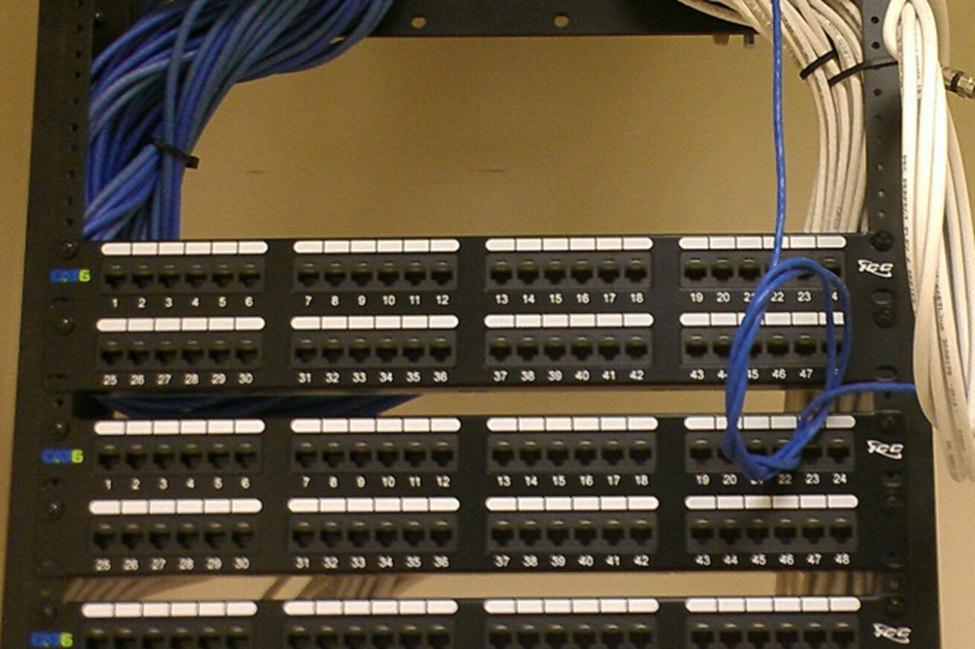
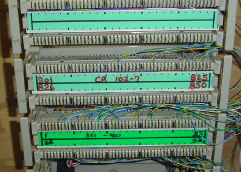
In a rack, the panels might look like the photo below
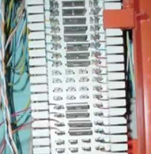
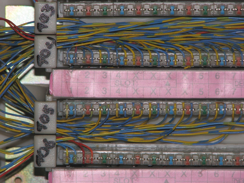
In a telecommunications system, we might use a wall-mounted block known as a 66, 110, or BIX block. Again, the name refers to the shape of the wire inserts.
The telecommunications blocks allow us to cross-connect a single wire at a time. We can connect many different types of copper wire to the block, including cat5e, cat6, or cat3.
Below is a 66 block. The blocks are used to cross connect cables. Wires coming from outside the system (wiring coming from a phone system or wiring coming from outside the building) are normally punched down to the left side of the panel. Building wiring is punched down to the right side. We add jumpers (the metal pieces in the middle of the block) to cross connect one side of the block to the other. Jumpers are also known as bridging clips.
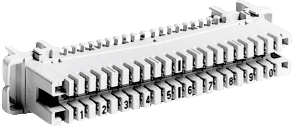
A 110 block is below. 110 blocks don’t use bridging clips but we can use a jumper wire to cross connect one side to another.
Similar to the 110 block is the BIX block. The BIX and the 110 blocks don’t take up much room.
Finally, we have the Krone block. Very few places use the Krone block.
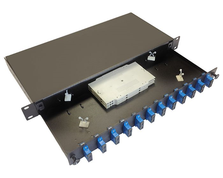
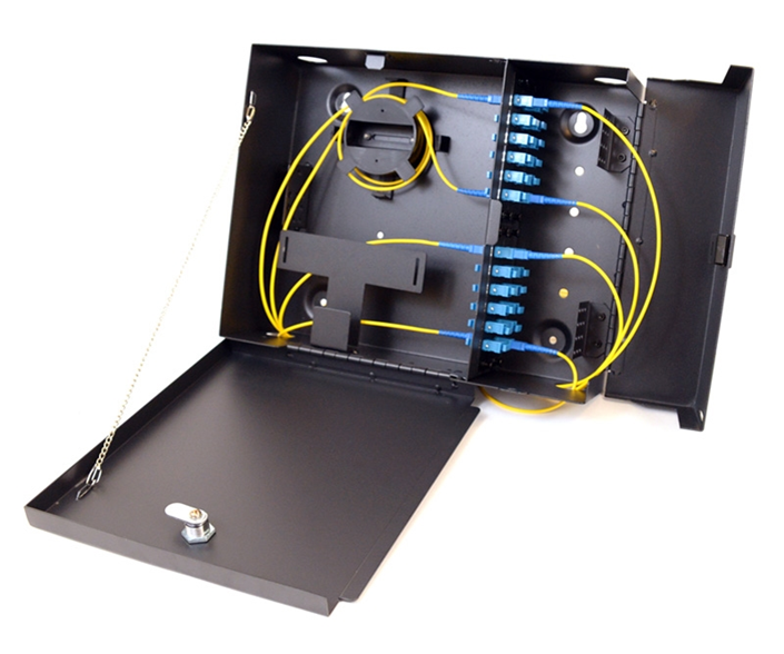
Fiber optic distribution panels can be rack-mounted or wall-mounted. Below is a rack-mounted patch panel. As you will notice, and as I said earlier, we can only terminate a fiber to a male end. The fiber panel below has female couplers at the front. We would run our fiber optic cable into the back of the panel and terminate it inside the panel. Then we can connect each terminated strand to the back of each coupler.
Below is an example of a wall-mount fiber optic patch panel. It also contains female couplers at the front. We can purchase the patch panels and the couplers separately, so that we can mix and match the types of connectors used by the system.
When two devices are connected via an ethernet cable, they will evaluate the wiring between themselves and agree on a speed and duplex setting, in a process known as autonegotiation. In a half-duplex setting, only one device can transmit at a time; the other device must listen. In a full-duplex setting, both devices can transmit and listen at the same time.
There are several standards for speed.
10Base-T was the original copper standard and could transmit at speeds of up to 10 Mbit/s. It could function over cat3 cable. 10Base-T is no longer popular.
100Base-TX came after. It can transmit at a speed of up to 100 Mbit/s over cat5 cable. 100Base-TX is also called 100BaseT or Fast Ethernet and uses two wire pairs – orange and green. One device listens on the orange pair and talks on the green pair, while the other device does the opposite. On a router, you might see ports labelled as FE for Fast Ethernet. The other four wires are not used.
1000BaseT is also known as Gigabit Ethernet. It uses all four pairs of an ethernet cable. 1000BaseT is the current standard, and you should not purchase network with components that operate at a lower speed than that.
A 100BaseT connection could be either full duplex or half duplex. A 1000BaseT connection must always be full duplex.
The next standard to develop was 10GBASE-T, which operates at 10 Gbit/s. 10GBASE-T requires cat6A cable but can operate over cat6 cable for short distances.
When 10GBASE-T came out, wireless access point manufacturers needed something better. As Wi-Fi popularity increased, manufacturers wanted to take advantage of the 10GBASE-T by implementing it in their access points. But building owners did not want to replace existing cat5e or cat6 wiring with cat6A. Thus, 2.5GBASE-T and 5GBASE-T were developed. They can provide 2.5 Gbit/s or 5 Gbit/s, respectively over existing cat6 cable.
Finally, 40GBASE-T was developed, which allows for speeds of 40 Gbit/s over cat8. 25GBASE-T with a speed of 25 Gbit/s and 50GBASE-T with a speed of 50 Gbit/s also exist. Both require cat8 cable.
An administrator can manually configure a switch/router/computer ethernet port to a specific speed and duplex setting but must then be careful to ensure that both connected devices/ports have the same settings, or they will not be able to communicate.
The standards that exist in the copper world also exist in the fiber world.
The early standard for fiber was 100Base-FX and 100Base-SX, which provided 100 Mbit/s over fiber. The FX standard worked over longer distances but used expensive lasers, while the LX standard worked over shorter distances and used cheaper LEDs.
1000Base-X is the standard for communication over fiber at 1Gbit/s. There are two main standards: 1000BaseLX uses single-mode fiber and can achieve distances of up to 10km, while 1000BaseSX uses multi-mode fiber and can achieve distances of up to 220 meters.
10GBaseT or 10 Gigabit Ethernet is a newer standard that allows devices to communicate at a speed of 10 Gbit/s. It can function over copper wiring or fiber. There are several fiber standards, including 10GBase-S (multi-mode fiber) and 10GBase-L (single-mode fiber).
10GBase-SR (for short range) provides speeds of 10 Gbit/s over multi-mode fiber at distances of up to 26m, while 10GBase-LR (for long range) provides speeds of 10Gbit/s over single-mode fiber at distances of up to 10km.
A 1000BaseLX SFP costs around $10 while a 10GBase-L SFP may cost up to $2000. Therefore, organizations prefer to use 1000Base-X when they can. 10 Gbit/s ethernet ports are only found on high-end infrastructure.
What if we have many signals to transmit simultaneously over a single fiber strand (or limited fiber strands)? We can combine the signal with a device called a multiplexer.
On one end of the fiber strand, we install a multiplexer, which joins optical signals (each with a different wave length) and sends them down the strand. On the other end of the strand, we install a demultiplexer, which separates the signals. There are three technologies here
- Coarse Wavelength Division Multiplexing (CWDM). Coarse refers to a wide separation between the wavelength of each signal. Specifically, the wavelengths are separated by 20 nm. For example, a signal at 1310nm and a signal at 1330nm can be transmitted over the same fiber at the same time.
- Dense Wavelength Division Multiplexing (DWDM). DWDM systems transmit signals with a much narrower wavelength separation. DWDM systems must operate very precisely as a small variation in the wavelength or the temperature of the laser can cause substantial loss in the signal. DWDM systems are used in very high bandwidth applications, and require repeaters every 100 km.
- Bidirectional Wavelength Division Multiplexing (WDM). Bidirectional WDM allows us to send a signal on a single fiber optic strand in both directions at the same time. This can happen because the signal in one direction has a different wavelength than the signal in the opposite direction.
How can you choose the best type of cable for your project?
- I don’t recommend coaxial for anything. The most common application is surveillance cameras, but I strongly recommend that you use ethernet based cameras.
- Install Ethernet cable between your server room and your wall outlets/surveillance cameras/wireless access points. The number of cables to each outlet depends on your needs, but for further guidance look at the BICSI TDMM (Telecommunications Distribution Methods Manual). The full design requirements are beyond the scope of this book.
- In general, use cat6 cable within your building and cat6A to the wireless access points. Remember that a single wall outlet is supporting only one device, but a wireless access point may support up to 50 devices, and thus a cable supporting a higher ethernet speed is warranted. Consider using cat6A for all your cabling if your budget allows.
- When the distance exceeds 100m, install multi-mode fiber. When the distance exceeds 1km, install single-mode fiber. Install a fiber optic cable with at least six strands so that there is adequate capacity for future upgrades. LC connectors are the most common.
- If you have an analog phone system, you may install some cabling between your telecommunications demarcation point and your server room. You can terminate this cabling to a BIX or 110 Block.
- Within a server room you may consider installing cat8 if required by your equipment. It may be better to purchase premanufactured cat8 patch cables and use them as required.
- 1 Gbit/s is the current minimum standard and you should configure your equipment to operate at this speed. Consider your needs and budget. Consider future upgrades, and whether it is better to buy faster equipment now or whether you will have funding to do it later. Connectors that operate at speeds faster than 1Gbit/s are more expensive.
- You may purchase switches that have the capability to operate at up to 40Gbit/s and then purchase the required SFPs at a later date (when the additional bandwidth is required).