
1.11 Describe wireless principles
1.11.a Nonoverlapping Wi-Fi channels
1.11.b SSID
1.11.c RF
1.11.d Encryption
A radio signal (like the one used in Wi-Fi and cell towers) is like a wave. It goes up and down. It is actually in three dimensions, but I can’t show 3D in a book. This wave is moving towards its target.
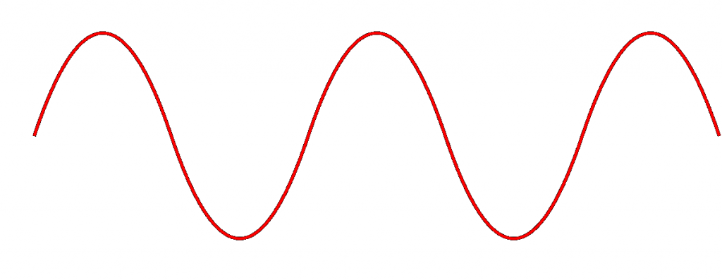
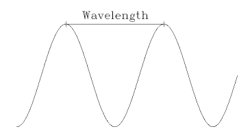
The height of the wave is called the Amplitude. The width of the wave is called the wave length. We can measure the wave from peak to peak.
No matter the height or the width, the wave travels at the speed of light (300,000,000 m/s). You can think of a Wi-Fi signal like light that you can’t see, because scientifically, that’s exactly what it is. It’s kind of like how we can’t hear a dog whistle, but dogs can – our ears filter our many sounds. Well, our eyes filter out many types of light.
Since all waves travel at the same speed, the wider the wave (the larger the wavelength), the less waves will pass through a point each second. We call this the frequency, measured as the number of waves that pass through a point per second. We measure frequency in Hertz (Hz).
If you had special glasses that would let you see radio waves in the air, it would look like a big mess of waves travelling everywhere. What we do is design each type of device to “look” for waves at a specific frequency and ignore the rest.
The government regulates the frequency that each type of technology can use. If everybody could broadcast signals at any frequency they wanted, the air would be a mess and no device would be able to keep track of their signals. Signals would interfere with each other.
Wi-Fi signals travel at a frequency of 2.4GHz and 5GHz.
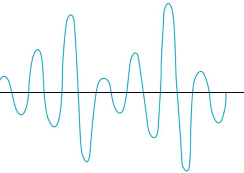
If we change the Amplitude of the wave over time (up and down), but keep the wavelength the same, we can use it to convey information.
The range of a Wi-Fi signal is between 50 and 300 feet. It is affected by signal interference (noise) from neighboring networks. Different wall types can block or reduce the signal (glass, concrete, steel will block signals more than drywall).
The 2.4GHz range has eleven channels. It has a longer range and is less vulnerable to noise than the 5GHz range, which has twenty-three channels. Older devices use the 2.4GHz range. But what’s a channel?
If I have a Wi-Fi network and my neighbor has a Wi-Fi network, the signals will interfere, and nobody will be able to understand anything. It’s like if two cars crash into each other from opposite directions. What happens? Both cars stop.
To solve this problem, we divide the 2.4GHz spectrum into 11 channels: Each channel is 22MHz wide, spaced 5MHz apart. Therefore, a 2.4GHz network is technically broadcasting on 2.412GHz, 2.417GHz, 2.422GHz, etc.
If two neighboring networks choose different channels, they will each broadcast on a slightly different frequency – different enough that their signals won’t interfere. We can manually select the channel that we want to broadcast our Wi-Fi on. We should survey the neighboring networks to see what channels they are broadcasting on and select a different channel from all of them. If we have multiple wireless access points in a building and their signals overlap, we should select a different channel for each of them.
The channel concept applies to 5GHz networks as well. A 5GHz spectrum is divided into 23 channels, each is 20MHz wide. A 5GHz spectrum can broadcast on 5.150GHz, 5.1570GHz, etc. There are more regulations for the 5GHz network and some countries do not allow some frequencies (they could interfere with weather radar and other systems).
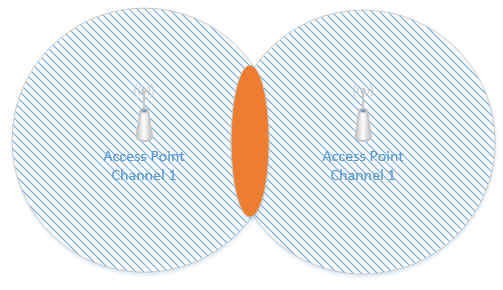
Interference is when two Wi-Fi signals cancel each other out. Consider the following access points, both of which are broadcasting on Channel #1. The signal is good, except where it overlaps, where it cancels out. A device in the red area is bombarded with signals from both access points at the same frequency. It doesn’t know which signal to listen to and won’t be able to connect to anything. The solution is to change the channel on one of the access points.
Remember how I said that a Wi-Fi channel is 22 MHz wide and that the channels are spaced 5 MHz apart? That means that on the 2.4 GHz range, the first channel is 2.412 GHz, but it actually ranges from 2.401 GHz to 2.423 GHz. The second channel is 2.417 GHz, but it actually ranges from 2.406 GHz to 2.428 GHz. That means that channels one and two overlap. If we look at the following diagram, we can see the overlap.
Channel #1 overlaps with Channels #2, #3, #4, and #5.

Thus, we should pick two channels that are far enough apart so that interference does not take place. The sixth channel ranges from 2.426 GHz to 2.448 GHz. In the above example, I should set one access point to broadcast on Channel 1 and the other access point on Channel 6.
5 GHz channels don’t overlap, so we don’t need to worry about selecting overlapping channels.
There are two other things we need to consider. An access point may only be able to handle fifty connections – this is an estimate for a high-quality access point; a poor-quality access point may only be able to handle twenty. If I have a conference room or theater with 200 or 400 occupants, even if the access point provides a good signal across the entire room, it may not have the capacity to connect to all the devices. Thus, we should install multiple access points to ensure that we have enough capacity.
In a larger area such as a warehouse with metal shelves, we may only have a few users, but the signal doesn’t travel far enough. It might get blocked by the shelves. We should install access points to ensure that the signal is at least -70 dBm everywhere.
We should also verify that our Signal to Noise Ratio (SNR) is at least 24. Noise is caused by wireless signals that are outside of our network. Devices such as cell phones, cordless phones, and microwaves can cause noise. Other wireless networks can also cause noise. If our SNR ratio is too low, we might need to add additional access points, move the existing access points, install shielding in the building, or remove the sources of noise.
On the 2.4 GHz network, only four channels don’t overlap – 1, 6, 11, and 14. Where possible, we should limit our Wi-Fi design to these four channels.
Consider this small rectangular room, which requires six access points due to many users.

If I space out the access points evenly and set them as best as I can so that there are no neighboring channels, they might look like this.
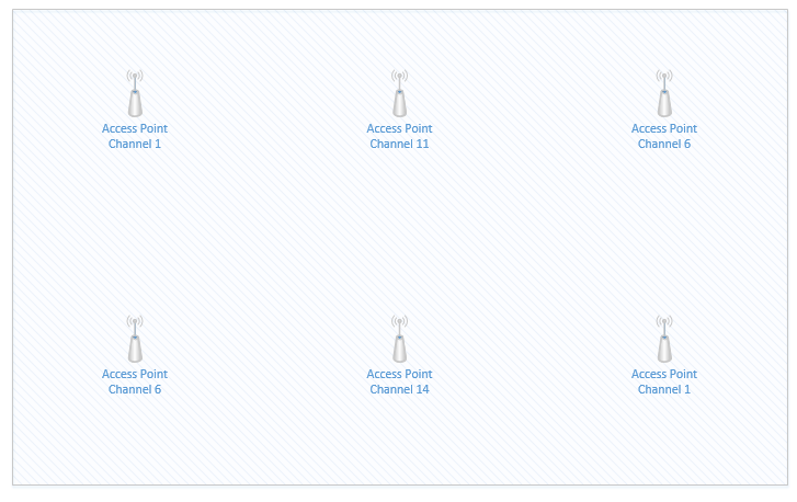
The access points that are on Channel #1 are in the top left corner and bottom right corner. If we highlight the coverage area of just those two access points, we can see that there is a significant overlap in the middle of the room (shown in red). The red area will have terrible coverage due to interference – there will be signals from two access points on Channel one. What can we do?
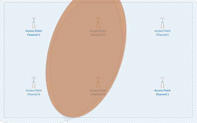
We can reduce the transmit power of each access point, so that the signal range is weaker. This way, the signals don’t overlap, but we can still cover the entire room with an adequate Wi-Fi signal. I can adjust the signal strength of an access point so that it doesn’t overlap with other access points or so that it does not leave the building.
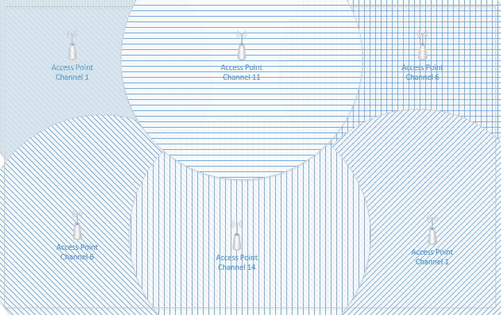
Now, I still have overlapping signals. But the overlap doesn’t extend across the entire room. The access points that overlap are broadcasting on slightly different frequencies; therefore, their signals do not interfere.
The BSSID or Basic Service Set Identifier is the name of the network. A Wireless Access Point, or WAP, advertises its capabilities and allows devices to join. The area where a WAP operates is known as the Basic Service Area, or BSA. It is the area where the WAP’s signal can reach host devices. In the example above, the BSA might be the room’s perimeter.
On an ad hoc network, The BSSID it is typically the MAC address of the device we are connecting to. We might call this the Independent Basic Service Set or IBSS. The purpose of an ad hoc network is so that two wireless devices can connect to each other without using a WAP. For example, I can print directly to a printer from my laptop or smartphone. The printer broadcasts an ad hoc wireless network and we connect to it from a laptop.
On an infrastructure network, the BSSID is known as an SSID or Service Set Identifier. On a larger network, it’s called an Extended Service Set Identifier or ESSID. When we have multiple access points, we force all of them to have the same ESSID so that users have the same experience regardless of where they are. Each access point has a unique BSSID, but all of them have the same SSID. We don’t want a user to change Wi-Fi networks when they move from room to room (or even within the same room).
We might call an end user device a client. When a client has connected to an access point, we call this an association. The purpose of a WAP is to allow wireless clients to reach the Ethernet network, and to allow clients on the Ethernet network to reach wireless clients.
A client will connect to the access point that is closest (technically, the access point that has the strongest signal). When a client moves from one WAP to another (on the same SSID), we call this roaming.
For example, say I have a large warehouse with hundreds of WAPs providing even coverage. If I turn on my laptop and walk around the warehouse, my laptop’s Wi-Fi connection will jump from one WAP to another, but it will appear like I’m always connected.
A single WAP can broadcast multiple SSIDs (for example guest, and corporate).
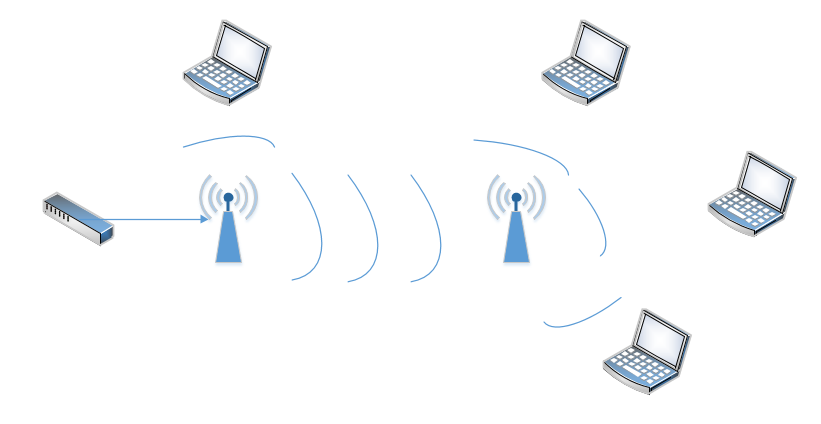
A wireless range extender is also known as a repeater. When placed at the edge of a wireless network, the range can be increased. Essentially, it repeats the signal that it “hears” from the nearest access point. It acts as a relay between the nearest access point and a user who is further away.
Consider the following scenario. On the left, I have an access point connected to a switch. Its range is shown by the circle around it. On the right, I have a user who wishes to connect, but is out of range. I don’t have the network infrastructure to install a second access point closer to the user.
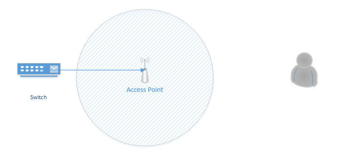
If I install a repeater, I now can extend the range of the access point to the user.
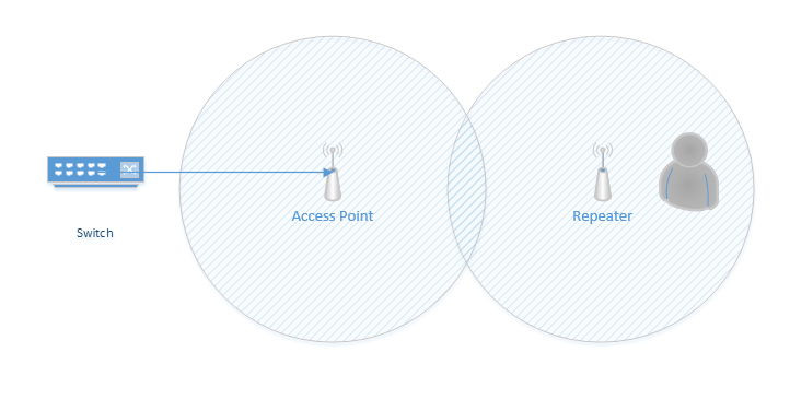
A repeater can be a normal AP that is set to “repeat” mode or it can be a special device. We usually change the repeater’s channel so that it doesn’t interfere with that of the original access point.
We can also use a workgroup bridge. A workgroup bridge is a device that connects to the Ethernet port of a host and allows it to connect to the wireless network. For example, if I have a portable X-ray machine or medical cart that moves around the hospital, but its only connection is to an ethernet port, I would connect it to ia bridge. The bridge can be a WAP that is set to bridge mode.
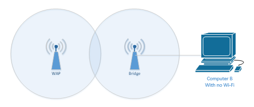
There are two types of bridges
- Universal Workgroup Bridge (uWGB). In a uWGB, one wired device connects to a wireless network.
- Workgroup Bridge (WGB). In a WGB, multiple wired devices connect to a wireless network.
What happens when we have multiple locations that must be connected via Ethernet, but can’t, due to distance or cost? For example, if I have two office buildings that are 1000m apart, but I would like to connect their networks together, I have several options. I can install a fiber optic cable between the buildings, but this would be expensive, and I may not have the right to dig up the land between them. I could install a WAN connection, but this may be expensive. Another option is to install a Point-to-Point antenna.
Below are two buildings, each with an Ethernet network. I can install an antenna on the roof of each building and point them at each other. I connect the antenna in each building to its respective Ethernet network via an Ethernet cable. The two antennas serve to bridge the networks and make them act like one.
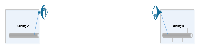
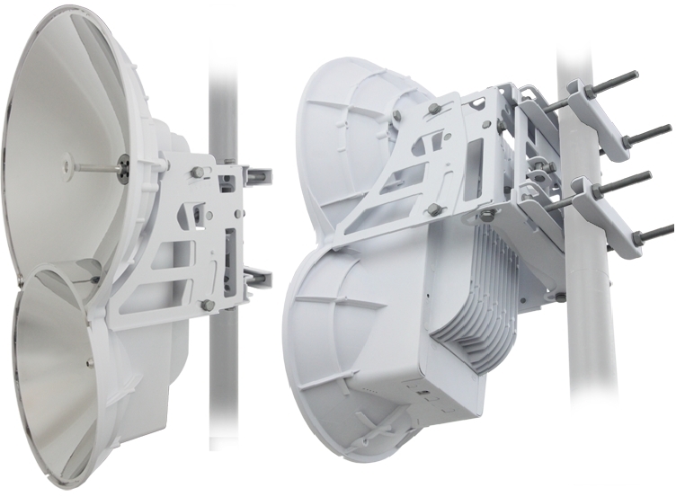
The antennas used in this case are highly specialized and must be pointed at each other. An example of a point-to-point antenna is the Ubiquiti AirFiber. This is not a Cisco product, but it is highly recommended by me.
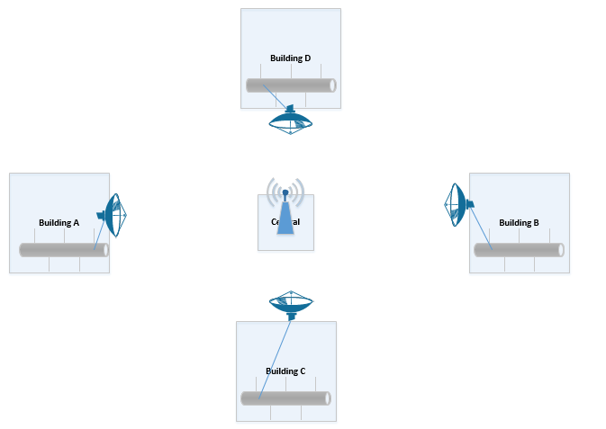
We can also create a point to multi-point configuration. One antenna (the central antenna) is an omni-directional antenna (it broadcasts its signal in all directions), while the others are unidirectional. Like before, each antenna connects to its Ethernet network via an Ethernet cable. We point all the unidirectional antennas at the central antenna.
A wireless mesh network is where multiple network devices such as access points form connections with each other and with clients. The mesh network is necessary in areas where we require Wi-Fi, but an access point cannot physically reach a switch or router.
Consider my crude mesh wireless network below. The access point on the left has as direct physical connection to the router. It can allow clients to connect to the network. The access point on the right is too far from the router or any wiring to connect over a direct physical connection. It forms a mesh wireless connection with the first access point. Devices on the right cannot connect to the access point on the left because they are out of range. With the mesh network, devices connecting to the access point on the right can connect to the network because the traffic will travel to the access point on the left, and then to the router.
We can continue to add more wireless mesh access points in a row or wherever we choose. But as the mesh grows, the data will need to pass through more access points, and therefore latency will increase.
The members of the mesh must understand the layout of the entire network so that they can route traffic to the appropriate neighbor and get it to its destination. There are dozens of mesh routing protocols; some are better than others.
All Wi-Fi protocols are regulated by IEEE (Institute of Electrical and Electronics Engineers). Collectively, we call them 802.11. As the demand for technology increases, new standards are released. The current standard is 802.11ac.
An access point or client (computer, phone, Wi-Fi adapter) may support multiple standards. The standards are backwards compatible (for example, an 802.11ac device will work with an 802.11a device).
Five standards have emerged
| 802.11a | 1999 Standard Supports up to 54 Mbps in the 5GHz range |
| 802.11b | 1999 Standard Supports up to 11 Mbps in the 2.4GHz range |
| 802.11g | 2003 Standard Up to 54 Mbps in the 2.4GHz range If all the devices on a network are at the 802.11g level, then the network operates at 54 Mbps. Otherwise, it operates at 11 Mbps to support the older devices. |
| 802.11n | 2009 Standard Supports multiple-input, multiple-output (MIMO) – an access point device with multiple antennas Up to 72.2 Mbps with one send and one receive antenna Up to 450 Mbps with three send and three receive antennas Also supports transmit beamforming which focuses the signal so that there are no dead zones It has a better way of supporting older devices. It can operate in one of three modes Legacy means it sends separate packets for older devices, which is not efficient Mixed means it sends out standard packets that support older devices and newer devices. We might also call this high-throughput or 802.11a-ht or 802.11g-ht. Greenfield means that it sends out 802.11n packets that support newer devices, but not older devices |
| 802.11ac | 2014 Standard Supports multiuser multiple-input, multiple-output (MIMO) Up to 433 Mbps per antenna, or 1.3Gbps with three antennas |
The standard provides guidelines that manufacturers of wireless devices use when making devices. With a reliable standard, products from different manufacturers all work together. Just think about it – it doesn’t really matter what brand laptop or phone you have, it generally works with the Wi-Fi at your office, your home, the airport, the mall, your friend’s house, etc. That’s because the Wi-Fi card in your device follows the same standard as the Wireless Access Points installed everywhere.