
1.2 Describe characteristics of network topology architectures
1.2.a 2 tier
1.2.b 3 tier
1.2.c Spine-leaf
1.2.d WAN
1.2.e Small office/home office (SOHO)
1.2.f On-premises and cloud
I bumped this section to the end because it wouldn’t make sense without some background information. Here is a switch. It has 48 ports. That means we can connect up to 48 ethernet devices to it (one might be a router). Actually, it has 52 ports, but we will worry about those ports on the end of the switch later.
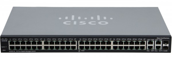
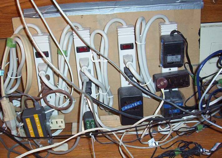
What if I have a big office with hundreds or thousands of computers? What if I have a massive network like at a University campus? I need to buy a bunch of switches and connect them together because one won’t be enough. But I need to think about it carefully. I can’t randomly connect switches, or they will become overloaded. You know if you have one power outlet and you randomly daisy chain power strips, you will have a big mess, and maybe even a fire. Well, it is worse with switches.
Some switches are powerful, and some are weak. Thus, I need to create a hierarchy.
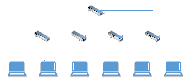
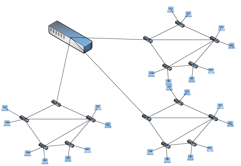
At the top, I can install a powerful switch, like a Cisco Catalyst 6500 switch. This is known as the core switch. On the second layer, I connect my less powerful switches to the core switch. We call these access switches, because the endpoints connect to them to access the network. This is a two-tiered network. A two-tier network is also called a collapsed core network.
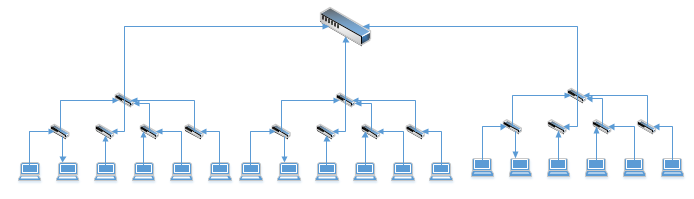
If I have a really, really big network, I can build it as three layers, or three-tiered. The switch at the top is called the core switch. The switches in the middle are called distribution switches. The switches at the bottom are called access switches. Ideally, each access switch should connect to two distribution switches in case one connection fails.
This kind of network is also called as a star network, because the points radiate from the switch.
An access switch connects to end user devices, but it does not connect to other access switches. A distribution switch aggregates data from access switches but does not connect to end user devices. A core switch forwards data between distribution switches, but it doesn’t connect to any end user devices or access switches.
This is opposed to a mesh network, where all the switches connect to each other. There is no central switch. When there are only a few switches, a mesh network might be acceptable. The problem with this network is that every switch needs to connect to every other switch. If we have 40 switches, then 39 out of 48 ports on every switch are used for cross-connects. That means that 39 ports are used to connect to switches and 9 ports are used to connect to endpoints.
If I have a network with 49 switches, then each switch needs 48 ports to connect to the other 48 ports and none of them can connect to endpoints.
That is a lot of cables and not very efficient.
When all the switches connect to all the other switches, we call it a Full Mesh.
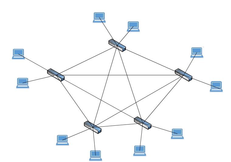
If only some of the switches connect to other switches, it is called a Partial Mesh.
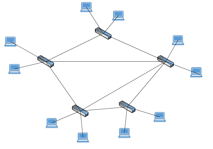
We can also combine a Mesh Network with a Star Network to make a Hybrid Network.
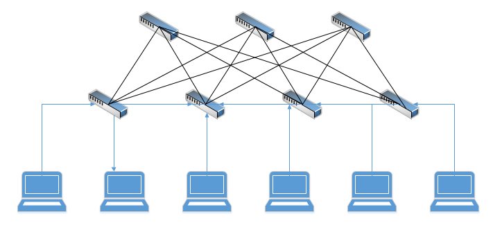
We also have a Spine-Leaf Network. At the top of the network is the spine (the spine switches). In the middle are the leafs (leaf switches). Each leaf switch connects to each spine switch, but a leaf switch never connects to another leaf switch. This kind of network is common in data centers and does not require core switches.
Okay, we are going to switch topics and look at how the internet gets into your home or office.
With a traditional internet connection, an Internet Service Provider (ISP) supplies you with a modem. The modem takes the signal from the ISP (a fiber, satellite, cellular, cable, or telephone connection) and converts it into an Ethernet connection that your network can use.
You connect the modem to your router or firewall and then you can access the internet. The problem with a traditional internet connection is that the ISP must install special equipment at its data center to transmit the signal to your modem (and to convert the signal to/from an Ethernet connection). The ISP must also supply and maintain modems at each customer location.
They had an idea. What if the ISP can build a massive Ethernet network across an entire city. Then you can just connect to their network without a modem.
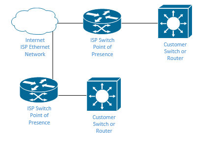
A Metro Ethernet, or MetroE, is a WAN service that improves upon the traditional internet connections. An ISP creates a large Ethernet network in a city. A MetroE is commonly found downtown but can be extended to the suburbs. The ISP provides the customer with an Ethernet connection directly to their network.
Typically, the customer connects its router’s outgoing port to the Ethernet connection provided by the ISP. The benefit is that the ISP doesn’t need to install or maintain any specialized equipment and doesn’t need to provide the customer with a modem. A customer could connect a switch to the ISP’s connection, but most people choose to use routers.
One benefit of a MetroE is that we can connect multiple physical locations together via an ethernet connection instead of via a dedicated WAN link.
What’s a WAN link? Well, let’s say I have offices in Atlanta, New York City, and Baltimore. I want to connect all three offices together so that their networks pretend like they are one big network. I would need to run a big long cable from New York City to Baltimore and Atlanta, which would be impossible. What I can do is pay my internet service provider to give me a special type of internet connection called a WAN, or Wide Area Network. The ISP carries my traffic from one local network to another and my networks don’t realize that they are physically separated. We will learn more about this later.
The connection to the ISP’s network is called an Ethernet Access Link. The spot where the ISP’s equipment ends, and the customer’s equipment starts is called the Point of Presence. The customer’s connection is called a User Network Interface.
There are several types of MetroE
- Ethernet Line Service or E-Line. This is a Point-to-Point connection between two devices. It is like a leased line in that each device thinks that it is physically connected to the other device.
- Ethernet LAN Service or E-LAN. This is a connection between multiple devices that acts like a Full Mesh network. All the connected devices think that they are physically connected to the same LAN and can exchange Ethernet frames.
- Ethernet Tree Service or E-Tree. This is a Hub-and-Spoke between multiple devices. The central device can communicate with the remote devices, but the remote devices can only communicate with other remote devices through the central device.
The Ethernet Line Service
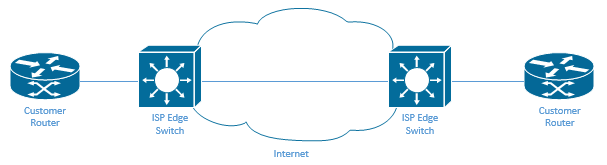
We configure each router to use a physical Ethernet interface. The IP addresses on the Ethernet interfaces are in the same subnet. The routers can exchange routes and become neighbors. Remember earlier I said that we need to allocate a subnet for each WAN interface.
On the edge of the ISP network is a switch (not a router or a modem). The switch helps carry Ethernet packets across the internet.
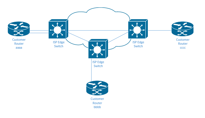
Every line needs its own subnet. That means that every router interface needs a unique IP address. The routers learn directly connected routes for any router connected by point-to-point.
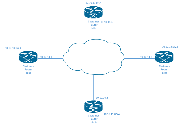
In my example below, Customer Router “aaaa” connects directly to Customer Router “bbbb” and to Customer Router “cccc”. Thus it learns a direct route to each of them.
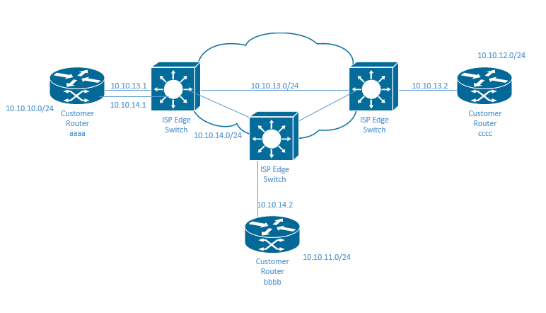
I created five subnets
| Subnet Name | Description |
| 10.10.10.0/24 | The local subnet for Router aaaa |
| 10.10.11.0/24 | The local subnet for Router bbbb |
| 10.10.12.0/24 | The local subnet for Router cccc |
| 10.10.13.0/24 | The WAN subnet for the Router aaaa-Router cccc connection 10.10.13.1 is Router aaaa’s external IP address on this WAN10.10.13.2 is Router cccc’s external IP address on this WAN |
| 10.10.14.0/24 | The WAN subnet for the Router aaaa-Router bbbb connection 10.10.14.1 is Router aaaa’s external IP address on this WAN10.10.14.2 is Router bbbb’s external IP address on this WAN |
Router aaaa’s routing table might look like this (I picked Physical Interfaces randomly).
| Subnet | Physical Interface | Next-Hop Router IP Address |
| 10.10.10.0/24 | G0/1 | Local |
| 10.10.11.0/24 | G0/2 | 10.10.14.2 |
| 10.10.12.0/24 | G0/3 | 10.10.13.2 |
| 10.10.13.0/24 | G0/3 | Local |
| 10.10.14.0/24 | G0/2 | Local |
Why?
- 10.10.10.0/24 is Router aaaa’s local network. It is directly connected to Router aaaa, so Router aaaa automatically learns it.
- 10.10.13.0/24 is Router aaaa’s local network on the WAN between itself and Router cccc, so Router aaaa automatically learns it.
- 10.10.14.0/24 is Router aaaa’s local network on the WAN between itself and Router bbbb, so Router aaaa automatically learns it.
- 10.10.11.0/24 is Router bbbb’s local network. Router aaaa learns this from Router bbbb. Router aaaa sends the traffic destined for this network to Router bbbb, via Router bbbb’s WAN IP address – 10.10.14.2.
- 10.10.11.0/24 is Router cccc’s local network. Router aaaa learns this from Router cccc. Router aaaa sends the traffic destined for this network to Router cccc, via Router cccc’s WAN IP address – 10.10.13.2.
An Ethernet Virtual Connection, or EVC is a Point-to-Point connection that determines which devices can communicate. A Point-to-Point connection is not practical when there are many sites because each router would need many physical interfaces and connections to connect to all the other locations over a full mesh.
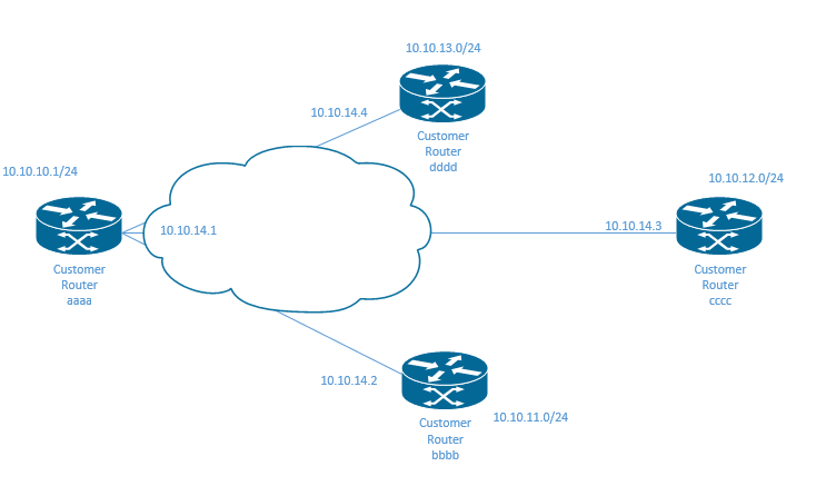
In an Ethernet LAN Service, we create a full mesh.
I created five subnets
| Subnet Name | Description |
| 10.10.10.0/24 | The local subnet for Router aaaa |
| 10.10.11.0/24 | The local subnet for Router bbbb |
| 10.10.12.0/24 | The local subnet for Router cccc |
| 10.10.13.0/24 | The local subnet for Router dddd |
| 10.10.14.0/24 | The WAN subnet for all of the routers 10.10.14.1 is Router aaaa’s external IP address on this WAN10.10.14.2 is Router bbbb’s external IP address on this WAN10.10.14.3 is Router cccc’s external IP address on this WAN10.10.14.4 is Router dddd’s external IP address on this WAN |
All the routers have an interface in the same subnet. Router aaaa’s routing table might look like this (I picked Physical Interfaces randomly).
| Subnet | Physical Interface | Next-Hop Router IP Address |
| 10.10.10.0/24 | G0/1 | Local |
| 10.10.11.0/24 | G0/2 | 10.10.14.2 |
| 10.10.12.0/24 | G0/2 | 10.10.14.3 |
| 10.10.13.0/24 | G0/2 | 10.10.14.4 |
| 10.10.14.0/24 | G0/2 | Local |
Why?
- 10.10.10.0/24 is Router aaaa’s local network. It is directly connected to Router aaaa, so Router aaaa automatically learns it.
- 10.10.11.0/24 is Router bbbb’s local network. Router aaaa learns this information from Router bbbb.
- 10.10.12.0/24 is Router cccc’s local network. Router aaaa learns this information from Router cccc.
- 10.10.13.0/24 is Router dddd’s local network. Router aaaa learns this information from Router dddd.
- 10.10.14.0/24 is the WAN’s subnet. All the routers connect to it. Since it is directly connected to Router aaaa, then Router aaaa automatically learns it.
The Ethernet Tree Service is less expensive and is good when there are many smaller sites. Each remote site connects to a central site.
Router aaaa’s table probably looks the same like in the previous example, and for the same reasons. It is directly connected to the other routers.
| Subnet | Physical Interface | Next-Hop Router IP Address |
| 10.10.10.0/24 | G0/1 | Local |
| 10.10.11.0/24 | G0/2 | 10.10.14.2 |
| 10.10.12.0/24 | G0/2 | 10.10.14.3 |
| 10.10.13.0/24 | G0/2 | 10.10.14.4 |
| 10.10.14.0/24 | G0/2 | Local |
The other routers are not directly connected to each other. If we look at router dddd, it has only two directly connected routes – its own subnet (10.10.13.0) and the connection to router aaaa (10.10.10.0) It must learn about the other two subnets (10.10.11.0 and 10.10.12.0) from router aaaa.
| Subnet | Physical Interface | Next-Hop Router IP Address |
| 10.10.10.0/24 | G0/1 | 10.10.10.1 |
| 10.10.11.0/24 | G0/2 | 10.10.10.1 |
| 10.10.12.0/24 | G0/2 | 10.10.10.1 |
| 10.10.13.0/24 | G0/2 | Local |
| 10.10.14.0/24 | G0/2 | Local |
The problem with all these scenarios is that they are not efficient. An ISP will not build a massive Ethernet network for a single customer. They will need to sell it to multiple customers. But they also need to keep customer traffic separated, even though many customers will use the same IP address schemes, subnets, and VLANs.
The ISP equipment on the MetroE edge is a switch because we want to forward Layer 2 Ethernet frames, not Layer 3 IP packets.
A good technology to support MetroE is called Multiprotocol Label Switching or MPLS. An MPLS creates a separate tunnel for each customer’s traffic without leaking any data. It operates on the ISPs network.
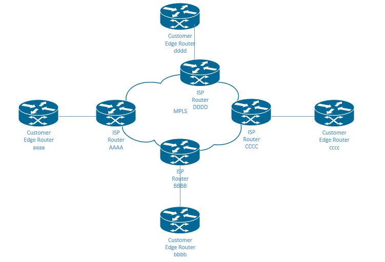
The router at the edge of each customer site is called an edge router. An MPLS forwards Layer 3 packets. The edge router is usually provided by the ISP.
The customer edge or CE is the router that is installed at the customer site and the provider edge or PE is the router that is installed at the edge of the provider’s network. One advantage of using a router is that the ISP can support many customers regardless of the type of data link that they are using. We can even access an MPLS network via a broadband connection if we can’t use a data link.
At the edge of each network, the router will add an MPLS header to the data packet and send it over the ISPs network. This header is called an MPLS label. The packet travels over the ISPs network until reaches the edge router on the other side. The edge router removes the MPLS header.
For example
- A device connected to Customer Edge Router aaaa’s LAN wants to send a packet to a device connected on Customer Edge Router cccc’s LAN
- Customer Edge Router aaaa receives the packet and adds an MPLS header to it
- Customer Edge Router sends the packet to ISP Router AAAA
- ISP Router transports the packet to ISP Router CCCC. The actual route might be complicated and pass through several ISP routers.
- ISP Router CCCC transports the packet to the Customer Edge Router cccc.
- Customer Edge Router cccc removes the MPLS header and sends the packet to the device
The service provider uses a routing protocol to learn routes between each of the customer’s edge routers and advertises those routes to all the other edge routers. That allows all the customer’s edge routers to learn all the necessary routes.
We can use Quality of Service or QoS on an MPLS network. The customer can mark high-priority traffic (such as those containing VoIP calls) and the MPLS network will forward them faster. The customer edge router is responsible for marking each packet, but the customer and the ISP must agree on a marking scheme.
All the edge devices (customer edge and provider edge) need to learn routes between each other. The customer can use any routing protocol that is available. The Customer edge router becomes a neighbor with the provider edge router. All the provider edge routers advertise their routes with each other so that all the customer edge routers can learn the network.
For example Customer Edge router aaaa knows about
- A directly connected route to its own local area network
- A directly connected route to ISP Edge Router AAAA
- Indirect routes to Customer Edge Routers bbbb, cccc, and dddd through ISP Edge Router AAAA (and therefore, indirect routes to ISP Edge Routers BBBB, CCCC, and DDDD through ISP Edge Router AAAA)
I didn’t put any actual IP addresses here because they aren’t as relevant, and we don’t know what the ISP’s network looks like. But router aaaa might have a routing table that looks like this.
| Subnet | Physical Interface | Next-Hop Router IP Address |
| Local aaaa subnet | G0/1 | Local |
| Local bbbb subnet | G0/2 | ISP Edge Router AAAA’s IP |
| Local cccc subnet | G0/2 | ISP Edge Router AAAA’s IP |
| Local dddd subnet | G0/2 | ISP Edge Router AAAA’s IP |
| ISP Edge Router AAAA | G0/2 | ISP Edge Router AAAA’s IP (directly connected) |
| ISP Edge Router BBBB | G0/2 | ISP Edge Router AAAA’s IP |
| ISP Edge Router CCCC | G0/2 | ISP Edge Router AAAA’s IP |
| ISP Edge Router DDDD | G0/2 | ISP Edge Router AAAA’s IP |
If the ISP network or if other parts of the customer network use a different routing protocol, the router uses a tool called a route redistribution to take routes from one protocol and advertise them on another protocol.
In particular, the ISP uses a tool called Multiprotocol BGP to readvertise routing protocols between the provider edge routers. MBGP is useful because it can separate routes between different customers. Remember that the ISP is using their network to support a WAN service for multiple customers and doesn’t want the routes or the data to mix.
If Goldman Sachs and Morgan Stanley buy WANs from AT&T, and each of them has offices in New York, New Jersey, Connecticut, and Florida, the data will probably travel over the same physical equipment, at least for part of the journey. Goldman Sachs shouldn’t learn about routes into Morgan Stanley’s network and Morgan Stanley shouldn’t learn about routes into Goldman Sachs’ network.
MBGP can label each route with the customer that it belongs to so that a Customer Edge will only learn or see the routes that belong to it.