
1.3 Compare physical interface and cabling types
1.3.a Single-mode fiber, multimode fiber, copper
1.3.b Connections (Ethernet shared media and point-to-point)
1.3.c Concepts of PoE
I’ve been drawing switches and connecting them with lines, but how do we physically connect all this stuff together?
There are two types of network cable: Copper and Fiber. When do we use copper and when do we use fiber?
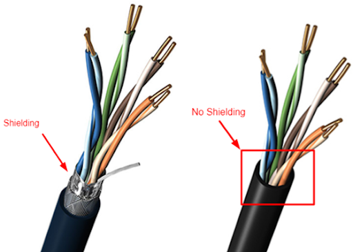
Most of the copper wiring in use is Unshielded Twisted Pair (UTP). This is a standard ethernet cable that contains eight wires, twisted into four pairs. The twists are designed to cancel out most forms of electromagnetic interference (from radio waves and nearby power lines), or noise. A single UTP cable can be up to 100 meters in length.
For more advanced applications, we can use a Shielded Twisted Pair (STP) cable. This is also known as F/UTP cable. The difference is that the STP cable contains a foil around the wires. The foil blocks out even more electromagnetic interference than the twists. The foil connects to the termination point on each end of the cable and acts as an electrical ground. STP cable is used in applications such as video transmission and in areas where there is a large amount of interference. If we peel back a cable, we can see the difference between a shielded cable and an unshielded cable.
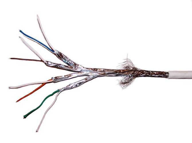
If we went crazy, we could buy a cable that had a separate shield around every pair. The shield protects the wires from electromagnetic interference. It also protects individual wire pairs from cross-talk (interference from a neighboring wire pair).
Most network devices are designed to accept a copper (UTP or STP) connection. That includes switches, IP cameras, computers, and VoIP phones.
Fiber optic cable can be run longer distances than copper. It also has a larger bandwidth (a fiber optic cable can carry more data than a copper cable). But fiber is more difficult to install than copper. It requires specialized equipment to test and terminate. A fiber optic cable uses light to transmit data, not electricity.
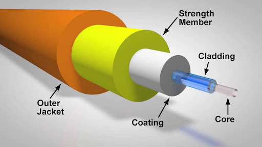
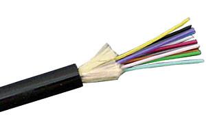
At the center of the cable is a glass core. Light travels through the core. Surrounding the core is a cladding, which prevents the light from escaping. The strength member is present in some cables and keeps it from breaking. Finally, the outer jacket protects the cable from rats that might chew on it.
We can’t connect a fiber optic cable to standard endpoint devices. For example, a VoIP phone or computer will not have a fiber optic cable connector. If we ran a fiber optic cable to a far away computer, we would need a device called a media converter to convert the fiber light signal to a copper electrical signal.
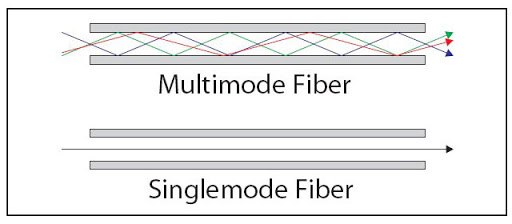
Fiber comes in two forms: single-mode, and multimode. Single mode cable can be run upwards of 200 km. A powerful laser generates a light signal, which travels down the center of the core as a single signal.
Multimode cable can be run up to 1 km. A weaker LED generates a signal, which bounces up and down inside the core. We can send multiple multimode signals at the same time. The cladding keeps it inside.
A single copper cable contains eight wires. When connected, a single copper cable carries data in both directions.
But a single fiber optic cable can contain multiple strands. A single strand carries data in only one direction. When we peel back the cable, we find multiple strands, which can be color-coded. We need at least two strands to make a circuit and carry data. Fiber optic cable typically comes with six or twelve strands.
There are three benefits to fiber (vs copper)
- It can be run longer distances
- It is not affected by electromagnetic interference. Powerful electrical signals or radio waves can distort the signal carried by copper wiring.
- Copper wiring gives off a signal. We could possibly try to spy on the signal carried by a copper cable.
Let’s say we wanted to connect a VoIP phone, an access point, or a surveillance camera to a network switch. These devices require power. But it’s a hassle to connect the device to an ethernet cable and to a power outlet.
What if we’re installing some surveillance cameras and don’t have nearby power outlets. We would need to hire an electrician to install some power outlets. A better solution is called PoE (Power Over Ethernet) comes in. PoE lets a switch power a network device.
PoE sends power down the Ethernet cable (it only works on copper, not fiber) to power a network device. That means a device can get power and data on the same cable.
There are several types of PoE.
- PoE is governed by the 802.3af standard and delivers up to 15.40 W.
- PoE+ delivers up to 30W.
- UPoE delivers up to 60W and UPoE+ delivers up to 100W.
- Cisco also offers a proprietary PoE standard called Cisco Inline Power, which delivers up to 7 Watts.
PoE and PoE+ use two pairs of wires to deliver power, while UPoE and UPoE+ use all four pairs.
When designing a network, you might consider the following
- A switch capable of delivering PoE is called a PoE switch and is typically more expensive than a non-PoE switch.
- You must choose a switch that has enough overall capacity to power all the devices connected to it. Just because UPoE+ can deliver up to 100W per port doesn’t mean that a 48-port switch will be able to deliver 4800W.
- Just because a device operates on UPoE+ and can accept up to 100W doesn’t mean that it will draw all 100W. It might draw much less. That means that overall, you don’t need as much power.
- A switch might be able to supply PoE on all its ports or only on some of its ports.
- In general, only the switches connected to endpoints need to support PoE. Switches that connect to other switches don’t need PoE.
- Some switches have hot-swappable power supplies. It is important to choose a power supply that supplies the switch with enough power to pass on to its connected devices and to operate the switch.
A switch that supplies power is called a Power Sourcing Equipment, or PSE. A device that receives power is called a Powered Device, or PD.
If you only had one or two devices that required PoE, you might connect a power injector instead. A power injector sits between the switch and the device requiring power. It takes data from the switch, adds power, and sends it to the device.
We don’t want to fry a device that doesn’t require power by sending it power. For example, we don’t want to send power into the Ethernet port on a desktop or laptop computer. How do we know that a device doesn’t need power if it hasn’t powered on yet?
The switch sends it a low power signal via Ethernet autonegotiation and wait for a reply. If the device doesn’t require any power (like a laptop or desktop), and its powered on, it will reply, and the switch will know that it doesn’t need to supply any power. Otherwise, if the switch can identify that the device requires power, it sends it enough power to boot up. The switch sends it the correct amount of power based on its power class.
The switch continues to monitor the device to determine whether its power class has changed. The device might tell us how many Watts of power it requires.
At the most basic level, all network devices need to be able to communicate with each other. Manufacturers gather together and develop common languages called protocols. As we will find out, some protocols are proprietary to Cisco devices – only Cisco devices understand them. But many are common to all network devices.
Why? Well, nobody has a monopoly on network and computing hardware. That means that devices from thousands of different manufacturers must work together. If you buy a laptop, it connects to the internet, and it doesn’t matter whose network you’re on. It just works, and that isn’t an accident. It’s because your laptop understands the same protocols as the network that you’re on.
One of these protocols is called Ethernet. Ethernet works at different speeds.
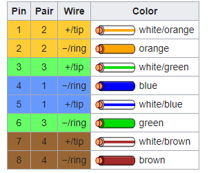
The most common is 100BaseT. It can transmit at a speed of up to 100 Mbit/s. 100BaseT is also called 100BaseTX or Fast Ethernet and uses two wire pairs – orange and green. One device listens on the orange pair and talks on the green pair, while the other device does the opposite. On a router, you might see ports labelled as FE for Fast Ethernet.
1000BaseT is also known as Gigabit Ethernet. It uses all four pairs of an ethernet cable. 1000BaseT is the current standard, and you should not install a new network with components that operate at a lower speed than 1000BaseT.
1000Base-X is the standard for communication over fiber at 1Gbit/s. There are two main standards: 1000BaseLX uses single-mode fiber and can achieve distances of up to 10km, while 1000BaseSX uses multi-mode fiber and can achieve distances of up to 220 meters.
A 1000BaseLX SFP costs around $10 while a 10GBase-L SFP may cost up to $2000. Therefore, organizations prefer to use 1000Base-X when they can. 10 Gbit/s ethernet ports are only found on high-end equipment.
10GBaseT or 10 Gigabit Ethernet is a newer standard that allows devices to communicate at a speed of 10 Gbit/s. It can function over copper wiring or fiber. There are several fiber standards, including 10GBase-S (multi-mode fiber) and 10GBase-L (single-mode fiber).
Gigabit Ethernet over fiber sends a different type of signal than gigabit Ethernet over copper, but all the different 10 Gigabit Ethernet standards use the same signal regardless of the type of cable.
Look at this Cisco switch. On the left are 48 copper ports. Each one can accept a single RJ-45-terminated cable (a copper cable). On the right are four additional ports – the bottom two are copper and the top two are “SFP”, or small form-factor pluggable transceiver.
You can’t plug a cable into an SFP port.
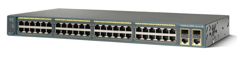
So, what’s the point? Well, there are many types of cables and available speeds – copper, single-mode fiber, multi-mode fiber, 10Gbit speeds, Gbit speeds, etc. Cisco can’t sell a different type of switch for every possible connector. And what if we had a network with several different types of cable? There could be millions of possible switch port combinations.
Cisco can’t manufacture millions of different switch models. Instead, the Cisco adds some “SFP” ports. Some switches have a few SFP ports and some have many.
Look at this switch. Almost all its ports are SFP ports.
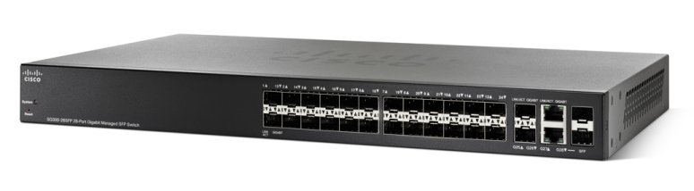
You figure out what kind of connections you require – copper or fiber (single-mode or multi-mode). And you decide the speed that you require – 1GB, 10GB, or 40GB. And if you’re using fiber, you decide what kind of connector you’re using LC, SC, etc.. Then you buy the right SFPs and insert them into the switch. An SFP could cost between $10 and $2000 depending on the speed. You can mix and match SFPs on a single switch.
An example of a copper SFP is below. You insert the SFP into an SFP port and then you insert the cable into the SFP. SFPs are hot-swappable. That means we can change them while the switch is powered on.
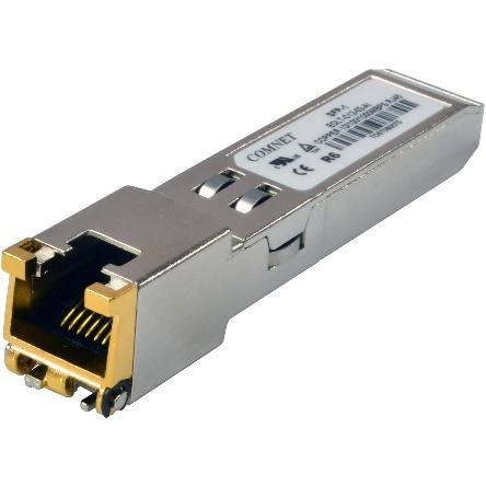
The maximum speed of an SFP is 1 Gbit/s, but the maximum speed of an SFP+ is 10Gbit/s. An SFP+ is also known as an enhanced small form-factor pluggable transceiver. An SFP+ works with fiber and copper connectors.
For even faster speeds, such as those required in the networks of major Internet Service Providers, the QSFP or Quad Small Form-factor Pluggable transceiver can be used. The QSFP can provide speeds between 4 Gbit/s and 200 Gbit/s.
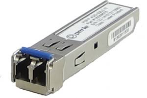
Below is an example of a fiber SFP. You will notice that it has space for two fibers. That is because a single stand of fiber typically operates in one direction at a time, whereas an ethernet cable operates in both directions at the same time. Thus, we would need two fiber strands to complete a “circuit”.
Now that we’ve connected our devices, let’s see what they actually say.
Ethernet works only on the LAN (Local Area Network) – that is the stuff behind your router. Ethernet only works between host devices (endpoints) and switches. When a device on a LAN wants to talk to another device on the same LAN, it breaks the message up into chunks. These chunks are called frames.
We sandwich our chunks between a header and a trailer. The headers contain important information like the sender and the destination. When we sandwich data between two headers, we say that it is encapsulated. This is very important, and we will come back to it later!

What is inside the header and trailer?
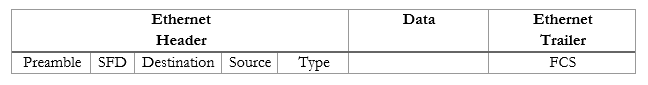
- Preamble (7 bytes long) – this is a warning that lets the recipient device know that important data is coming so that it can get ready to listen. It gives the recipient some time to get ready. Think of a switch or computer just sitting there. Frames are electrical signals travelling down the Ethernet wire, bit by bit. The switch can’t predict when the next frame will show up, and a new frame might catch it off guard. So, the preamble kind of makes it pay attention.
- SFD (1 byte long) – this is a warning that important data will start on the next byte. The switch knows that the preamble is over, and it must record any data after the SFD.
- Destination (6 bytes long) – the destination MAC address. Every network device has a unique address called a MAC address. The MAC address is burned into the device from the factory. It’s kind of like a serial number.
- Source (6 bytes long) – the source MAC address.
- Type (1 byte long) – the type of data we are using.
- Data (between 46 and 1500 bytes) – the actual data (the chunk). If our data is less than 46 bytes, we add some “padding” to make it at least 46 bytes.
- FCS (4 bytes long) – the Frame Check Sequence – kind of a signature. The sending computer calculates an FCS from the data that he sends. The receiving computer performs the same calculation on the data that is received. If the recipient obtains the same result, then he knows that the data was received without any errors.
If the FCSs don’t match, the recipient assumes that the data has been corrupted and throws it out. We call this error detection. We’ll worry about how we recover from errors later.
This isn’t a big deal, because we broke our data up into frames. We don’t need to resend all the data – only the bad frames.