
1.5 Compare TCP to UDP
But how do devices talk to each other, really? What do they say? How do messages get from one LAN to another? Remember I said that devices on a LAN talk to a switch and the switch forwards the frame based on the MAC address. What if they are on different LANs? Their traffic must pass through the router.
Devices speak a language called TCP or Transmission Control Protocol.
TCP involves a connection between two devices, with a three-way handshake. When using TCP, each time a device receives data, it verifies that the data has been received correctly. If not, the recipient requests that the sender retransmit the data.
TCP works with another protocol called IP, or Internet Protocol, and together they are called TCP/IP.
We think of TCP as being a connection-oriented protocol. It’s like two people approaching each other at a park and agreeing to have a conversation:
- Person One: “Hey can I talk to you?”
- Person Two: “Sure”
- Person One: “Okay, I acknowledge that you agree to let me talk to you. Here is what I need to say: blah, blah, blah”
- Person Two: “I acknowledge what you said”
- Person One: “Thanks, blah, blah, blah some more”
What are these messages called?
- The first message is called the SYN (hey can I talk to you?). It is actually requesting that the parties synchronize their communication method.
- The second message is called the SYN-ACK (sure). The second party is requesting synchronization and acknowledging receipt of the first message.
- The third message is called the ACK (Okay, I acknowledge…). The first party is acknowledging receipt of the second party’s message.
When we want to terminate the connection, we send a message called FIN.
TCP is a connection-oriented protocol because it requires us to create a connection before we can transfer data.
Under TCP/IP, every device has a unique address called an IP address. The IP address is 12 digits, and every three digits are separated by a period. We call each set of three digits an octet, and the value of each octet ranges from 0 to 255. For example, 111.111.111.111 is an IP address. So, every device has unique IP address and a unique MAC address.
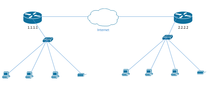
In my example, I have two LANs connected over the internet. On the left is a LAN where the router IP address is 1.1.1.1, and on the right is a LAN where the router IP address is 2.2.2.2.
Right now, it’s not important how they got these addresses. The devices inside the LAN also have IP addresses, but it’s also not important.
Remember how Ethernet breaks long messages up into frames? Well, in TCP/IP, these chunks of data are called packets.
What happens when a computer in the LAN on the left wants to send data a computer in the LAN on the right?
- The computer on the left determines that the destination computer isn’t on the same LAN. Based on that, it creates a packet with the destination IP address. The destination IP address is the IP address of the router on the right. It’s the IP address of the router, not the computer.
As we will see learn later, we might never know the IP address of the computer on the right, and the LAN on the right is responsible for forwarding the packet to from the router to computer. The LAN on the left only has to worry about getting the packet to the LAN on the right.
Our IP header might look like this
| IP Header | TCP Header | Data |
- We still need to take this packet from the computer on the left to the router on the left. Thus, our computer encapsulates this packet into an Ethernet frame. The frame is addressed to the MAC address of the local router.
| Ethernet Header | IP Header | TCP Header | Data | Ethernet Trailer |
- The switch receives the frame and, based on its MAC address, forwards it to the router. It checks the table to see what port the router is connected on.
- The router receives the frame, and strips the Ethernet header and trailer, revealing the IP Header inside.
| IP Header | TCP Header | Data |
- Based on whatever magic is inside the router, it sends this packet to the router on the right.
- The router on the right receives the packet and realizes that it is addressed to a computer inside its LAN. It adds new Ethernet headers, which include the MAC address of the destination computer. Now this is a frame again.
| Ethernet Header | IP Header | TCP Header | Data | Ethernet Trailer |
- The switch in the network on the right receives the frame from the router and forwards it to the correct computer.
How all this works deep inside each device is something we will learn more about in the coming chapters.
By the way, a UDP Header only has four components and is a total of eight bytes.
| Source Port | Destination Port | Length | Checksum |
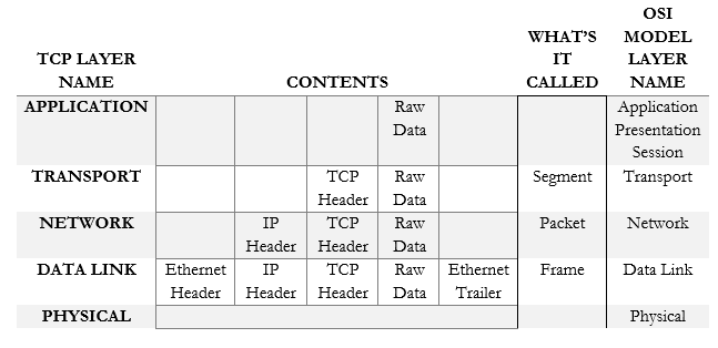
The OSI Model was invented to explain the internet. It has seven layers and even though it doesn’t make a whole lot of sense anymore, we still teach it to people. A better model is the TCP Model, which has five layers that follow the OSI Model.
Data is created at the top layer and works its way down until it gets to the bottom layer where it is transmitted. You can think of it as an assembly line. Each layer adds something to the data – specifically, each layer adds a header and possibly a trailer to help the data get to its destination. What are the layers of the TCP Model, and how do they correspond to the OSI Model?
- Application Layer (Equivalent to the Session, Presentation, and Application Layers of OSI). The application layer allows programs to talk to the network. It contains the raw data generated by each computer program.
- Transport Layer (Equivalent to the Transport Layer of OSI). The transport layer moves the packets. Data from the application layer enters the transport layer and is encapsulated into segments.
- Network (Internet) Layer (Equivalent to the Network Layer of OSI). IP Packets are created on the Internet Layer. Segments from the transport layer receive IP Headers with their source and destination IP addresses.
- Link Layer (Equivalent to the Data Link Layer of OSI). TCP isn’t concerned with the link layer, because the TCP/IP protocol doesn’t define the physical link. Packets from the Internet layer receive Ethernet Headers and Trailers, resulting in frames.
- Physical Layer (Physical layer of OSI). The physical layer is the actual wiring with 0’s and 1’s traveling along it. The data is transmitted in this layer via an electrical signal (or light if we’re using fiber optic cables).
We can summarize the information in the following table
If we don’t want to use TCP, we can use UDP. UDP is a connectionless protocol because it does not require a connection. UDP is like if I went to the top of a hill and started yelling. Nobody agreed to hear my message and it’s possible that nobody will hear me. VoIP and other services use UDP.
When we communicate within a TCP layer (from computer to computer), we call it same-layer communication. When we communicate on a single computer between layers, we call it adjacent-layer communication.
Let’s take a closer look at our routers. Behind each router is a LAN. Your home network is a LAN. Your work network is a LAN. Each device on a LAN knows that it is on a LAN and it can tell whether other devices are on the same LAN.
What if I had two offices, or five offices, or hundreds of offices, all over the country, and I wanted to make them into one big LAN? Let’s say I have a server in Baltimore and I need to access it from my office in Los Angeles.
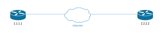
The solution is a WAN, or Wide Area Network. A phone company or an internet service provider lets some magic happen between our routers so that they can pass traffic over the internet but pretend to be part of the same physical network. We call this connection a leased line, WAN, Point-to-Point, etc..
The ISP provides you with an internet connection that works on the most basic layer. It’s up to you to find a protocol to transmit the data between your routers. The two most popular protocols are HDLC or High-Level Data Link Control, and PPP, or Point-to-Point Protocol.
Since we’re pretending that our LANs are part of the same physical network, it would be logical for our routers to transfer frames and not packets.
The HDLC frame is slightly different from an Ethernet frame. HDLC is an international standard, but Cisco routers use a proprietary version. Let’s take a look.
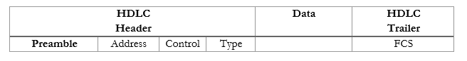
- Preamble (1 byte) – this lets the receiving router know that some data is coming
- Address (1 byte) – the destination MAC address
- Control (1 byte) – this field is no longer in use
- Type (2 bytes) – proprietary to Cisco; tells us the type of data in the HDLC frame
- Data – the data that we’re transmitting
- FCS (2 bytes) – Frame Check Sequence
What happens in our network when the computer on the left wants to send some data to the computer on the right? Now these computers are on separate LANs connected via a WAN. We need to understand that every computer has an IP address – now it’s relevant.
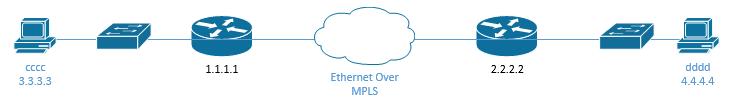
- The computer on the left determines that the destination computer on the right isn’t on the same LAN. Based on that, it creates a packet with the destination IP address. The destination IP address is the IP address of the computer on the right.
In this example, we have a WAN, so the computer in the left knows the IP address of the computer on the right (4.4.4.4) but can’t reach it through the LAN.
| IP Header Dest: 4.4.4.4 | TCP Header | Data |
- The computer encapsulates this packet into an Ethernet frame. The frame is addressed to the MAC address of the local router.
| Ethernet Header | IP Header | TCP Header | Data | Ethernet Trailer |
- The switch receives the frame and, based on its MAC address, forwards it to the router.
- The router receives the frame, and strips the ethernet header and trailer, revealing the IP Header.
| IP Header | TCP Header | Data |
- The router encapsulates the frame into an HDLC header and sends it to the router on the right.
| HDLC Header | IP Header | TCP Header | Data | HDLC Trailer |
- The router on the right strips the HDLC headers to reveal the original IP packet created by the computer on the left
| IP Header Dest: 4.4.4.4 | TCP Header | Data |
- The router on the right adds new Ethernet headers, which include the MAC address of the destination computer
| Ethernet Header Dest: dddd | IP Header | TCP Header | Data | Ethernet Trailer |
- The switch in the network on the right receives the frame and forwards it to the correct computer
As I said earlier, every router only must worry about its own LAN, and nothing else. Now we can see that every router needs to get traffic to the next router (the neighboring router). If it can get traffic to the other network, it isn’t concerned with how the other LANs operate internally.
Increasingly, ISPs are providing customers with ethernet connections known as ethernet WANs. An ethernet WAN acts like if we connected two routers together with a cross-over ethernet cable, no matter how far apart those routers are. Some other names for this service are Ethernet Line Service, or Ethernet over MPLS (EoMPLS).
When we use an Ethernet WAN, we don’t need to worry about the HDLC protocol anymore. Routers forward normal ethernet packets between themselves.
How?
- The computer determines that the destination computer isn’t on the same LAN. Based on that, it creates a packet with the destination IP address. The destination IP address is the IP address of the computer on the right.
| IP Header Dest: 4.4.4.4 | TCP Header | Data |
- The computer encapsulates this packet into an ethernet frame. The frame is addressed to the MAC address of the local router.
| Ethernet Header | IP Header | TCP Header | Data | Ethernet Trailer |
- The switch receives the frame and, based on its MAC address, forwards it to the router.
- The router receives the frame, and strips the ethernet header and trailer, revealing the IP Header.
| IP Header Dest: 4.4.4.4 | TCP Header | Data |
- The router encapsulates the frame into a new Ethernet header and sends it to the router on the right. This new header has the MAC address of the router on the right as the destination.
| Ethernet Header | IP Header | TCP Header | Data | Ethernet Trailer |
- The router on the right strips the Ethernet headers to reveal the original IP packet created by the computer on the left
| IP Header Dest: 4.4.4.4 | TCP Header | Data |
- The router on the right adds new Ethernet headers, which include the MAC address of the destination computer
| Ethernet Header Dest: dddd | IP Header | TCP Header | Data | Ethernet Trailer |
- The switch in the network on the right receives the frame and forwards it to the correct computer
What if my network is more complicated? In the previous scenario, each router only had one destination. What if there are more than two routers? A large corporate network has hundreds of routers.
Let’s look at a more complicated network. I have four LANs now
- LAN 1, where IP addresses start with 1
- LAN 2, where IP addresses start with 2
- LAN 3, where IP addresses start with 3
- LAN 4, where IP addresses start with 4
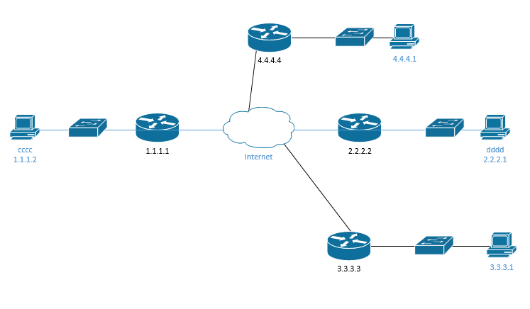
First, think about the computer on the left. It’s preprogrammed to understand that if a packet’s destination is outside its own LAN, then it should send it to the LAN router. This router is known as the default gateway. The computer has no other choice – a LAN could have multiple routers, but this is a rare setup. The router is responsible for sending the packet to the next network (the next router).
But how does the router (1.1.1.1) know where to send the packet to? It has a routing table. Router 1.1.1.1’s table might look like this
| Interface # | destination |
| Fe0/0/0 | 2.2.2.2 |
| GE0/0/0 | 3.3.3.3 |
| ge0/0/1 | 4.4.4.4 |
By the way, a router can have multiple interfaces, or ports to connect to. You will see interfaces labelled as “FE” for Fast Ethernet (100 Mbps) or “GE” for Gigabit Ethernet (1 Gbps), and then a number such as FE0/0/0.
- Let’s say that computer 1.1.1.2 wants to send a packet to computer 3.3.3.1. It knows that computer 3.3.3.1 is on network 3.
- It knows that network 3 is different from its own network (network 1), so it encapsulates the packet in a frame and sends the frame to its default router. The frame contains the MAC address of the default router. The switch sends the frame to the router.
| Ethernet Header | IP Header Dest: 3.3.3.1 | TCP Header | Data | Ethernet Trailer |
- The router receives the frame and checks the FCS to ensure that there are no errors
- It strips the ethernet header and trailer, leaving just the IP header
| IP Header Dest: 3.3.3.1 | TCP Header | Data |
- The destination is 3.3.3.1, which is part of the 3.3.3.3 network
- From the table, the router knows that network 3.3.3.3 is connected to GE0/0/0
- The router creates a new frame addressed to the router running the 3.3.3.3 network. The frame’s sender field contains the MAC address of the 1.1.1.1 router, and destination field contains the MAC address of the 3.3.3.3 router.
| Ethernet Header | IP Header Dest: 3.3.3.1 | TCP Header | Data | Ethernet Trailer |
- It sends this frame out of interface GE0/0/0
- The router on network 3.3.3.3 receives the frame. It strips the ethernet header revealing the IP address 3.3.3.1
- It creates a new frame and sends it to computer 3.3.3.1 (addressed to the computer’s MAC address). The switch is responsible for forwarding the frame.
We call each of these networks (1.1.1.1, 2.2.2.2, 3.3.3.3, 4.4.4.4) subnets. If a group of computers is connected over a switch, then they should be part of the same subnet. If they are separated by a router (or multiple routers), then they are part of different subnets.
Remember our routing table? How did the router fill this table out?
| Interface # | destination |
| Fe0/0/0 | 2.2.2.2 |
| GE0/0/0 | 3.3.3.3 |
| ge0/0/1 | 4.4.4.4 |
I made the network a little bit more complicated. Now there are multiple pathways. If router 1.1.1.1 needs to send data to 6.6.6.6, it has a couple of options. It must go through 2.2.2.2, and then it can either go through 3.3.3.3 or 4.4.4.4. How does it decide which route to take? How does it even know what routes there are?
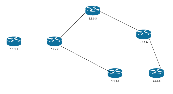
When we first connect a router, it automatically learns about the subnets that it’s directly connected to. It adds those subnets to the table
- Router 1.1.1.1
- Router 1.1.1.1 knows about subnet 1.1.1.1 (its own local network)
- It also knows that it’s connected to subnet 2.2.2.2 (the neighbor)
- Router 2.2.2.2
- Router 2.2.2.2 knows about subnet 2.2.2.2 (its own network)
- It also knows that it’s connected to subnets 1.1.1.1, 3.3.3.3, and 4.4.4.4 (its neighbors)
- By the same logic
- Router 3.3.3.3 knows about subnet 3.3.3.3, 6.6.6.6, and 2.2.2.2
- Router 4.4.4.4 knows about 2.2.2.2, 4.4.4.4, and 5.5.5.5
- Router 5.5.5.5 knows about 4.4.4.4, 5.5.5.5, and 6.6.6.6
- Router 6.6.6.6 knows about 3.3.3.3, 6.6.6.6, and 5.5.5.5
That means router 2.2.2.2 might have a routing table that looks like this
| Interface # | destination |
| Fe0/0/0 | 2.2.2.2 |
| GE0/0/0 | 1.1.1.1 |
| ge0/0/1 | 3.3.3.3 |
| GE0/0/2 | 4.4.4.4 |
And router 1.1.1.1 might have a table that looks like this
| Interface # | destination |
| Fe0/0/0 | 1.1.1.1 |
| GE0/0/0 | 2.2.2.2 |
Once each router fills out its own table, it shares the table with its neighbors
- Router 1.1.1.1 tells 2.2.2.2 about 1.1.1.1
- Router 2.2.2.2 tells 1.1.1.1 about 3.3.3.3 and 4.4.4.4
- Router 2.2.2.2 tells 3.3.3.3 about 1.1.1.1 and 2.2.2.2
- Router 2.2.2.2 tells 4.4.4.4 about 1.1.1.1 and 2.2.2.2
Each router updates its table
- Router 2.2.2.2 doesn’t need to update its table with the info it learned from 1.1.1.1, because it’s directly connected to 1.1.1.1 and 1.1.1.1 is only connected to 2.2.2.2. Thus, 1.1.1.1 has no new information to share with 2.2.2.2.
- Router 1.1.1.1 updates its table to include routes to 3.3.3.3 and 4.4.4.4. Now it knows that it can reach networks 3.3.3.3 and 4.4.4.4 through router 2.2.2.2.
- Now router 1.1.1.1’s table looks like this
| Interface # | destination |
| Fe0/0/0 | 1.1.1.1 |
| GE0/0/0 | 2.2.2.2, 3.3.3.3, 4.4.4.4 |
- Although it’s not directly connected to 3.3.3.3 or 4.4.4.4, router 1.1.1.1 knows that it can reach those networks through 2.2.2.2. Thus, any traffic with a destination of 3.3.3.3 or 4.4.4.4 can travel through the GE0/0/0 interface.
Router 1.1.1.1 doesn’t have to worry about how Router 2.2.2.2 gets traffic to 3.3.3.3 or 4.4.4.4. It just needs to know that it can do so.
How do the routers actually talk? How do different brands of routers talk to each other? We will find out later.
We’re going to stop and learn some background information.
I’ve been talking about MAC addresses for a while. A router or computer needs to address Ethernet frames to another router or computer’s MAC address. How do devices learn the MAC address of the destination?
That’s where ARP or Address Resolution Protocol comes in. Let’s say my computer has a MAC address of AA:AA:AA:AA:AA:AA and an IP address of 192.168.1.2, and my printer has a MAC address of BB:BB:BB:BB:BB:BB and an IP address of 192.168.1.3. I want to print a document. My computer knows my printer’s IP address, but it needs to find out its MAC address.
My computer sends out a message known as an ARP request message. It addresses the message to the broadcast MAC address FF:FF:FF:FF:FF:FF. Remember that messages to this address go everywhere.
My computer’s message in effect says, “if your IP address is 192.168.1.3, then tell me your MAC address”. This message is flooded over the entire network, but only the printer responds (because only the printer has that IP address). The printer sends an ARP response message back to my computer, indicating that its MAC address is BB:BB:BB:BB:BB:BB. By the way, the switch on my network sees these messages and uses them to learn MAC addresses of the connected devices.
My computer maintains a table called the ARP table. It adds the information learned from the printer’s ARP response to the table. The ARP table contains a list of device MAC addresses and their corresponding IP addresses. The next time my computer wants to talk to the printer, it doesn’t need to follow the ARP process and send out an ARP request message. It just checks the table. In fact, every time a computer needs to send an ARP message, it checks the ARP table first to make sure that there isn’t already a valid entry.
Routers also keep records of ARP addresses. They need to know the MAC addresses of computers on their subnets and of neighboring routers. A router lets the entries in its ARP table expire after a period, because addresses can change.
We can look up the ARP entries on our computer by typing arp -a
The second item I want to mention is DNS. Humans are good at remembering names but bad at remembering numbers. A human can remember hostnames and website URLs like google.com and amazon.com. Unfortunately, for a computer to access a website, it must know the IP address of that website’s server. How does a computer convert a URL like google.com into an IP address like 8.8.8.8?
The DNS or Domain Name Server converts human-readable domain names into machine-readable IP addresses.
It’s easy for me to remember a name like “fileserver01”, but my router/computer needs to know it as 192.168.5.5. When I type in “fileserver01”, my computer calls the DNS and says “hey, what’s the IP address for fileserver01” and the DNS replies with “192.168.5.5”. Now I can send my traffic to 192.168.5.5 (or use ARP to learn 192.168.5.5’s MAC address).
ICMP is a special protocol. It does not carry user traffic, but machine-to-machine communications. Network equipment use ICMP messages to communicate errors and status updates with each other. ICMP messages are used by ping and tracert commands. These commands are important for network troubleshooting.
For example, if I want to check whether a device with the IP address 192.168.5.5 is online, I can send it a “ping”, also known as an ICMP Echo Request. If the computer is online, it sends a reply, known as an ICMP Echo Reply.
We will look at the benefits of TCP/IP in greater detail
- Multiplexing. We can use virtual ports to send different streams of traffic to the same computer.
- Segmentation. Data is segmented into packets before being transmitted instead of being sent as a continuous stream. It’s like if I ripped pages out of a book and sent them to you one at a time.
- Error Recovery. The system numbers each packet so that the recipient is forced to acknowledge receipt. Any packet not received is sent again.
- Flow Control. We can use buffers to prevent high traffic flows from overloading network devices. If a computer receives a ton of traffic all at once, it can hold some of it in a buffer until it has the resources to process it.
- Connections. Devices must agree to communicate before they can communicate. We talked about this at the beginning of this chapter.
What is a port? For the purposes of this section, a port isn’t something physical. If you look at the back of your computer, you’ll see USB ports, HDMI ports, VGA ports, and probably a single network (Ethernet) port. We’re not talking about those ports. A port is simply a virtual channel that an application can use to communicate with a specific protocol. All the data entering your computer travels through that single physical Ethernet port (or through a Wi-Fi connection), but it must be separated somehow so that every application receives the information it needs.
Say your computer’s IP address is 192.168.1.5, and you’re receiving the following traffic
- A file transfer through FTP
- Some web pages through Google Chrome
- A Zoom meeting or a Skype meeting
This traffic is all addressed to your computer’s IP address – 192.168.1.5 and is divided into packets. How does each application know which packets belong to it? For example, how does Google Chrome know which packets contain web pages?
That is where these “virtual” ports come in. There are 65,535 different ports. Some of the smaller numbered ports are reserved for specific protocols. For example, HTTP is port 80. Unencrypted website (HTTP) traffic travels on port 80.
Each application only sends data out of, and listens for data on, the specific ports that it requires. For example, Google Chrome sends and receives web traffic over HTTP (port 80) and HTTPS (port 443). Therefore, Google Chrome only listens for traffic on ports 80 and 443 and sends traffic only on ports 80 and 443. It cannot see data on other ports.
When we send a packet with a webpage, we address it to 192.168.1.5:80. Google sees this traffic and takes it.
In general, a port is reserved for only one protocol, and the applications that use a protocol will use the ports reserved for that protocol.
In more advanced cases, two devices could choose to use a different port. For example, an HTTP web server could choose to listen/transmit on a different port than port 80 or port 443, such as port 8343. Then a device attempting to access the web server would need to know to use the non-standard port 8343. When a user instructs Google Chrome to visit a website, it tries to communicate with the web server over port 80 or port 443. If the web server is configured for another port, Google Chrome will display an error. Google Chrome must be configured to look for the website data on the non-standard port.
The real-world equivalent of a port is a set of post office boxes. Each tenant has his own box. The mail comes in to the post office from many locations. The street address on each envelope is the same, but the post office box is different. The post office sorts the mail into each post office box. When a recipient comes in to check his mail, he can only look inside his own box. He doesn’t see any mail addressed to another person, even though they share the same street address.
Some of the most common protocols are summarized in the following table. Remember that an administrator can run a protocol over a non-standard port number. The port number has no effect on the contents of the traffic.
| Port Number/Name | Use |
| 20 and 21/FTP | File Transfer Protocol FTP is a protocol for transferring files between two devices FTPS adds a security layer to the file transfer. It requires that the server have an SSL certificate installed. The entire session can be encrypted or only specific portions of the session can be encrypted. |
| 22/SSH | Secure Shell Secure Socket Shell (or Secure Shell) allows a user to connect to a remote computer. SSH authenticates the identity of the remote computer to the user and the user to the remote computer. SSH creates a tunnel between the user and the remote computer. The user will require an SSH client such as PuTTY, and the remote computer will require an SSH daemon. Each remote computer must be set up to accept SSH logins (typically over port 22). Network firewalls must be configured to allow traffic over port 22. The user’s IP address should be whitelisted on the firewall (do not allow SSH connections from any IP address) |
| 22/SFTP | SSH File Transfer SFTP is a file transfer protocol within the SSH protocol. Provided that the SSH session is secured and properly configured, then the SFTP session will be as well. |
| 23/Telnet | Telnet Telnet provides a text-based terminal to communicate with a network device or server. Telnet is like SSH but does not contain any security. It is no longer popular due to lack of security. |
| 25/SMTP | Simple Mail Transfer Protocol Used to communicate with an e-mail server (for sending e-mail only). Can be secure or insecure, depending on whether the client and server agree to encrypt data between them. |
| 53/DNS | Domain Name Server Translates Domain Names/Hostnames to IP addresses (necessary to locate network resource) Consider that a human can remember text names (such as google.ca or amazon.com), but for a web browser to access a website, it must figure out the corresponding server IP address. The DNS converts human-readable domain names into machine-readable IP addresses. |
| 67/68/DHCP | Dynamic Host Configuration Protocol Allows a device to request a dynamic IP from a DHCP server. Allows a DHCP server to dynamically assign IP addresses to other devices. When a device first joins a network, it may not need an IP address and must request one. |
| 69/TFTP | Trivial File Transfer Protocol TFTP is like FTP in that it allows a user to transfer files over a network. TFTP has a simple design. An important use of TFTP is to allow a device to boot over a network. A device with no operating system can load one over the network into memory. |
| 80/HTTP | Hyper Text Transfer Protocol Used to transmit web site data (insecure) |
| 110/POP | Post Office Protocol Allows an e-mail client like Outlook to retrieve messages from a server. With POP, the e-mail server receives messages on behalf of the user. The e-mail client asks the server if there is any new messages. If so, the e-mail client downloads messages from the server. The server deletes the messages after they have been downloaded. POP is no longer common; it has been replaced with IMAP and Exchange, which allow an e-mail client to “sync” with a server. |
| 123/NTP | Network Time Protocol NTP allows network-connected devices to sync their clocks, to within a few milliseconds of UTC. NTP can function accurately even when the network has high latency through the clock synchronization algorithm. NTP can obtain the time from a central server or from a peer. |
| 137-139/NetBIOS/NetBT | NetBIOS/NetBT Developed by Microsoft in the 1980s. Allows computers to communicate with each other over a network and exchange basic information. When a computer booted up, it broadcast its information (MAC address and hostname) so that other computers on the network could find it. NetBIOS only worked for small networks of up to 40 devices, with no router. NetBIOS over TCP/IP (or NetBT) was an upgrade. Provides name services (provides each computer with a unique hostname), and communications. |
| 143/IMAP | Internet Message Access Protocol Allows an e-mail client to communicate with an e-mail server. The client and server “sync” so that both have the same data (e-mails, calendar entries, contacts, etc.). If an e-mail is deleted in the e-mail client, then it is also deleted on the server. IMAP may be secure or insecure. |
| 161/162/SNMP | Simple Network Management Protocol Allows a user to collect and manage data about managed network devices, including routers, switches, servers, and printers. |
| 389/LDAP | Lightweight Directory Access Protocol Allows users to access different directories Directories include e-mail directories, users, phone numbers, printers, and services |
| 427/SLP | Service Location Protocol Allows computers to find services on a local network A device will broadcast a URL containing the location of a service that it offers over SLP Other devices can connect to the URL over SLP to use the service |
| 443/HTTPS | Hyper Text Transfer Protocol-Secure Used to transmit web site data (secure) |
| 445/SMB/CIFS | Server Message Block/Common Internet File System Allows computers on a network to share files and printers |
| 548/AFP | Apple Filing Protocol Allows Apple devices to share files |
| 636/LDAPS | Secure Lightweight Directory Access Protocol Like LDAP but secure |
| 1720/H.323 | Allows devices to communicate audio-visual content over a network. Used in videoconferencing applications. |
| 3389/RDP | Remote Desktop Protocol Allows a user to remotely connect to a Windows server or computer via a Graphical User Interface |
| 5060/5061/SIP | Session Initiation Protocols Used for real-time communications involving VoIP and video conferencing. Also used by mobile devices for voice over LTE. |
Ports 0 to 1023 are well known ports reserved for specific applications. Only those applications should be using those ports. Ports 1024 to 49151 are called user ports or registered ports. An application developer can apply to have his application use one of those ports. Ports 49152 to 65535 are called private ports, dynamic ports or ephemeral ports. An app can borrow one of those ports temporarily if it needs to communicate.
In TCP/IP, an IP address combined with a port and a transport protocol (TCP or UDP) is called a socket. For example, 192.168.5.5:80 over UDP is a socket. The use of ports is called multiplexing.
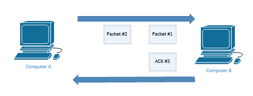
Reliability or error recovery allows the sender to ensure that its message is received. Each TCP packet is numbered with a Sequence number. It’s kind of like pages in a book. How does it work?
Computer A sent Packet #1 and Packet #2 to Computer B. The packets are numbered sequentially. The next packet will be Packet #3.
Computer B replies with an acknowledgement telling Computer A that it received the two packets. It numbers its acknowledgement “3”. Notice that it didn’t number it “2”, or “1”. It doesn’t have to acknowledge all the packets that it received. Instead, Computer B is saying that it received all the packets up to (but not including) Packet #3. This is known as a forward acknowledgment, because it is acknowledging that it expects to receive Packet #3 next.
By the way, remember I said that in a TCP handshake the computers send a message called “SYN”? “SYN” is short for synchronize. Basically, each computer is telling the other one to synchronize its sequence numbers. Computer A doesn’t have to start with Packet #1. It could start the could at 23424 or something. It doesn’t matter, if both computers agree on a starting value.
Anyways, Computer A knows that Computer B received Packet #1 and Packet #2 because it receives ACK #3. It can send more packets.
Now, let’s look at a different example. Although they look alike, this is a different Computer A and Computer B than in the previous example, believe me.
Computer A sends four packets to Computer B. Packet #1 through Packet #4 are sent but Packet #3 fails to reach its destination. Computer B receives Packet #1, Packet #2, and Packet #4, and realizes that Packet #3 is missing. It sends Computer A an acknowledgement for Packet #3. Computer B is saying that it expects to receive Packet #3 next.
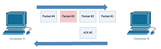
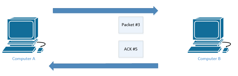
Computer A reads the ACK #3 and realizes that Computer B didn’t receive Packet #3. It’s not sure whether Computer B received Packet #4. Thus, Computer A resends Packet #3.
Upon receipt of Packet #3, Computer B responds with an acknowledgement expecting the next packet to be Packet #5. Computer B already received Packet #4 earlier, so it doesn’t need to receive it again.
By not having to send an acknowledgement for every packet, we can reduce the amount of traffic that we send over the network.
The concept of Flow Control or windowing allows two computers to decide how many packets can be awaiting acknowledgement. For example, if the size of the window is five, then Computer A will send Computer B five packets. Once Computer B has acknowledged receipt of the five packets, Computer A can send more packets.
The two computers can adjust the size of the window during their connection. They can adjust the size of the window during each transmission. When they do, it is known as a sliding window or a dynamic window. The receiving computer uses the ACK message to tell the sender the size of the new window.
Each time a computer receives messages successfully, it increases the size of the window. Each time it receives messages unsuccessfully, it reduces the size of the window. A good network is like a well-oiled machine. Computers are not usually waiting to send traffic, and eventually, the window is so big that the computers send and receive traffic continually.