
2.1 Configure and verify VLANs (normal range) spanning multiple switches
2.1.a Access ports (data and voice)
2.1.b Default VLAN
2.1.c Connectivity
The first part of this book gave you some background information about networks and a general idea of how they communicate. We are going to learn more about those concepts later. But now it is time to start configuring Cisco equipment. Let’s get a few facts out of the way
- Cisco calls each physical port on a switch or router an interface.
- The operating system on a Cisco device is called IOS, or Internetwork Operating System
- We talk to the switch or router through a Command Line Interface (CLI). There are three options
- Telnet (by knowing the device’s IP address). You shouldn’t use Telnet because it is not secure. But we will learn Telnet anyways because Cisco wants us to.
- SSH (by knowing the device’s IP address)
- Console cable (physically connect to the switch or router)
- If you have a USB console port on the switch or router, you can connect a USB cable from the switch or router to your computer. Newer switches and routers have USB console ports.
- If you have a serial console port on the switch or router, you can connect a console cable (known as a rollover cable) from the switch or router to the serial port on your computer.
- If you have a serial port on the switch or router, but you don’t have a serial port on your computer, you can connect a serial-to-USB cable on your computer
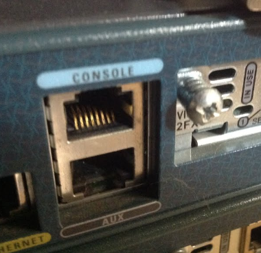
The console port on a switch or router says Console and is usually blue. Newer devices usually have both a USB and a serial console port. The console port is serial, but it is in the shape of an RJ-45.
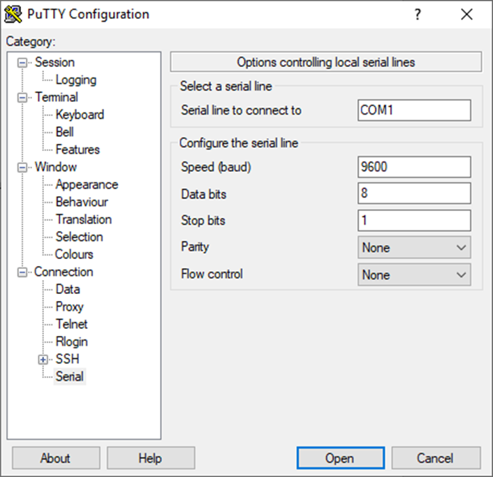
To talk to the device, you must run a program called a terminal emulator. The most popular program is called PuTTY. The settings that you should configure in PuTTY
- 9600 bit rate
- No Flow Control
- 8-bit ASCII
- No parity bits
- 1 stop bit
These settings are usually default in PuTTY (except for the flow control).
When we first console in to the switch or router, it will put us in the user EXEC mode. We can view settings but can’t change any configuration.
We are in user mode if the prompt looks like
Switch>
If we type the enable command, we enter the enable mode. We can enter more commands in the enable mode. We still can’t change the configuration. We can exit enable mode by typing disable.
We are in enable mode if the prompt looks like
Switch#
To change the configuration, we must enter the configuration mode. That is entered by typing configure terminal. We can exit the configuration mode by typing end. We can’t enter configuration mode from user mode; we must be in enable mode first.
Even when we’re in the configuration mode, we can only configure certain aspects of the device. We need to enter additional commands to change certain aspects of the configuration. For example, to configure an interface, we must type interface <interface name>. Summary of the configure modes
| What the prompt looks like | What it’s called | Why? | Command to get there? |
| Switch(config)# | Global | Basic configuration | configure terminal |
| Switch(config-line)# | Line | Configure logins | line console 0 |
| Switch(config-if)# | Interface | Configure interfaces | interface <name> |
| Switch(config-vlan)# | VLAN | Configure VLANs | vlan <number> |
From the config-line, config-if, or vlan, we can type exit to return to the main config prompt.
Some things to remember
- There are many commands and you don’t need to memorize them all. If you’re logged in to the switch, and you’re not sure, type ?
- If you’re not sure about a specific command, type <command>?, where <command> is the name of the command.
- In enable mode, there are many commands that allow us to see the status of the device or certain aspects of it. These commands usually start with show. For example, the show ip interfaces command gives us a detailed status of the interfaces on a router.
- Many commands can accept a modifier at the end. A common modifier on the show commands is brief. The brief modifier gives us summary information. For example, the show ip interfaces brief command gives us a summary table containing the status of the interfaces on a router.
- Many configuration commands have modifiers as well. Going forward, I will write any command in this font. The parts of the command that you might need to change will have <> around them. For example ip address <IP address> requires you to enter an IP address in place of <IP address>. You might type ip address 192.168.0.1.
When you have a choice of what to type, I might separate the options with a |. For example, switchport mode [trunk|access], means that you must choose either trunk or access. You might enter switchport mode trunk or switchport mode access. - In the configuration mode, many commands can be reversed by typing no in front of the command. For example, we can shut down an interface by typing shutdown. We can turn the interface back on by typing no shutdown.
- The switches and routers are smart. If we type only part of a command and there are no other matching commands, the device will execute the command.
For example, we don’t have to type the full command write memory. We can type write mem, or wr memory, or wr mem. There are no other commands that start with wr or mem, so the device knows what we are trying to type.
The console remembers the last ten commands that you typed. If you want to view a previous command, press the Up arrow. You can also press the down arrow. To edit, you can move the cursor left and right.
The configure terminal mode remembers the last ten commands that you typed in configure terminal mode, and the enable mode remembers the last ten commands that you typed in the enable mode. If you type some commands into the enable mode, and then enter configure terminal, you won’t see those commands in your history.
We can view the commands we previously typed with show history. We can type terminal history size <length> to change size of the history buffer just for the session that we are in.
From the configure terminal mode, we can type history size <length> to change length of the history buffer for all sessions. For example, if I want to keep the buffer at a length of 40 commands, I would type history size 40.
The switch or router has three types of memory
- Flash Memory – the flash memory is where the switch stores its operating system and back up configuration files
- ROM – this is Read Only Memory, which helps the switch boot up and load its operating system
- NVRAM – the switch stores its main configuration file in the NVRAM. When the switch boots up, it loads its configuration from the NVRAM
- RAM – when the switch boots up, it loads its operating system into the RAM. Then it loads its configuration into the RAM.
There are two types of configuration files
- The startup-config is the configuration file that loads when the switch is powered on
- The running-config is the configuration file that the switch is using while it is powered on. The running-config comes from the startup-config (when the switch boots it copies the startup-config into the running-config).
If we change the config, only the running-config is updated. Any change to the config is live immediately; there is no need to save changes, but if we reboot the switch, the startup-config returns and all of our changes are lost.
Therefore, we need to save the running-config (overwrite the startup-config with the running-config) so that the changes are saved.
If I want to see the config on the device, I can type
- show startup-config to view the startup-config
- show running-config to view the running-config
The device will only show the first few lines of the configuration (or of any lengthy output). If we want to see more, we just press Enter.
If I want to save my configuration changes, I can type copy running-config startup-config, which means that I want to copy my running-config (which I just changed) overtop of the startup-config. I could also type write memory.
To erase the existing configuration, I can type
- write erase
- erase startup-config
- erase nvram:
and then reboot the device. When the device reboots, its configuration will be blank. I can reboot the device by typing reload.
If I want to change the name of the device (the hostname), I type hostname <name>
If I want to add some security, I have three options
- Security to protect the user mode with a password (through the console)
- line console 0 – now I’ve entered the login configuration mode (for the console only; this doesn’t apply to users who connect over Telnet or SSH)
- login – this tells the switch/router to prompt for a password for the user mode
- password <password> – where <password> is the password I want to use
- line console 0 – now I’ve entered the login configuration mode (for the console only; this doesn’t apply to users who connect over Telnet or SSH)
- Security to protect the user mode with a password (through the Telnet/SSH)
- line vty 0 15 – now I’ve entered the login configuration mode (for the Telnet/SSH only)
- login – this tells the switch/router to prompt for a password for the user mode
- password <password> – where <password> is the password I want to use
- line vty 0 15 – now I’ve entered the login configuration mode (for the Telnet/SSH only)
- Security to protect the enable mode. I configure the following
- enable secret <password> – this requires us to enter a password when we enter the enable mode
- I could also write enable password <password>– but this is less secure
- If I wanted to remove the password, I could type no enable password
We will look at security in more detail in Section Five.
A few things to note
- If we are logged in to a device via a console cable, then every time a status changes, the switch or router posts a message in the console. These messages can get annoying. We can suppress the messages by typing no logging console
- The device will log you out of the enable mode times out after five minutes of in activity. exec timeout <minutes> <seconds> can change the timeout. If we wrote exec timeout 0 0, the switch would never timeout.
- In exec mode, if you type in an unknown command, the switch or router thinks that you are trying to Telnet into another device. It performs a DNS lookup and fails, which forces you wait about a minute. You can suppress this behavior by typing no ip domain-lookup
On a switch, we can troubleshoot connected devices
- I can see the MAC address table by typing show mac address-table. If I want to search for a specific MAC address, I type show mac address-table address <address>
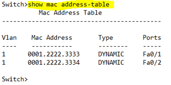
For example, show mac address-table address 0001.2222.3334 will only show entries with the MAC address 0001.2222.3334. This is useful for when the MAC Address Table has many entries and we can’t read through all of them.
- If I want to filter MAC addresses based on the interface that it was learned on, I can type show mac address-table dynamic interface <interface name>, where interface name is the interface name.
For example, show mac address-table dynamic interface Fa0/1 will only show entries on port Fa0/1. - If I want to filter MAC addresses based on the VLAN that it was learned on, I can type show mac address-table dynamic vlan <VLAN number>, where VLAN number is the VLAN number.
For example, show mac address-table dynamic vlan 1 will only show entries on VLAN 1.
The entries in the table stay there for 300 seconds (5 minutes). If the traffic comes in, the timer is reset to zero. We can change the aging time to something else
- mac address-table aging-time <time> – we can change the aging time globally
- mac address-table aging-time <time> vlan <VLAN number> – we can change the aging time per VLAN
If the table fills up, the oldest entries are removed, even if they were seen after than the aging time. We can fit about 8000 entries in the table. We can manually clear the table of the entries, by typing
- clear mac address-table dynamic vlan <vlan number> – clears all the MAC addresses associated with a specific VLAN
- clear mac address-table dynamic interface <interface number> – clear all the MAC addresses associated with a specific interface
- clear mac address-table dynamic address <MAC address> – clear entries associated with a specific MAC address
- clear mac address-table dynamic – clears the entire table
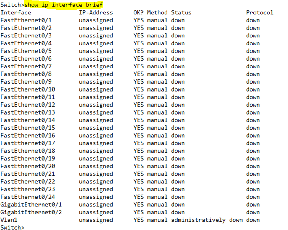
If I want to see the status of each interface, I can type show ip interface brief. If I want to see more details, I can type show ip interfaces. Below is the output of my interface command, showing that all the interfaces are down.

On a switch, by default, each interface is enabled. When the interface is disabled, we say that it is shutdown. On a router, by default, each interface is disabled.
When we run the show ip interface brief command, we can see the “status” and “protocol” columns. The status tells us whether the interface is physically connected to another device and receiving an electrical signal. The protocol tells us whether the interface is receiving traffic.
The status might be down if there is no cable connected to it, there is a cable connected to it but the cable is damaged, there is a cable connected to it and to another device, but the other device is powered off or its port is shutdown.
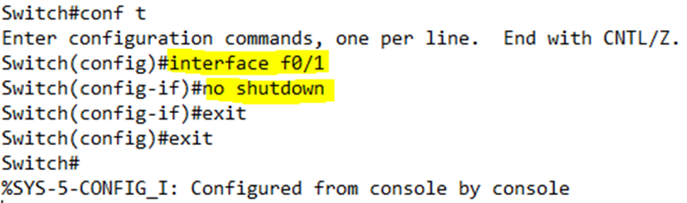
We type shutdown to disables an interface. The status of the interface becomes “administratively down”. We type no shutdown to enable the interface.
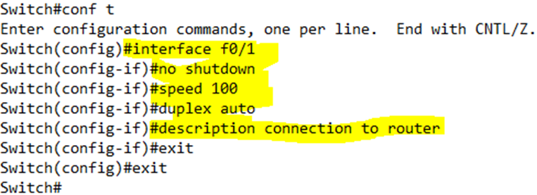
In the below example, I configured no shutdown on Interface F0/1. I first had to enter the configuration mode, and then I had to enter the Interface F0/1 configuration mode.
When we connect two devices together, they will agree on a speed and duplex setting through a process called auto-negotiation. We can manually change the speed and duplex setting on an interface.
- duplex [auto | full | half] will adjust the interface’s duplex setting. Choosing auto allows it to automatically negotiate the speed. For example, duplex half will set the interface to half duplex.
- speed [auto | 10 | 100 | 1000] will adjust the interface’s speed setting. For example, speed 100 will set the interface speed to 100 mbps.
We can add a description to an interface by typing description <text>. This command is useful for human viewers of the configuration but has no effect on the device.
In the below example, I set the description to “connection to router”, the speed to 100 and the duplex to auto.
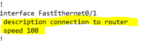
I checked the configuration after making these changes. Notice that “no shutdown” is missing. When we configure a shutdown or no shutdown command, it doesn’t appear in the configuration of the interface, but it does appear in the status of the switch interface.
Also, notice that “duplex auto” is missing. When we set the speed or duplex to auto, the switch doesn’t list the setting in the configuration.
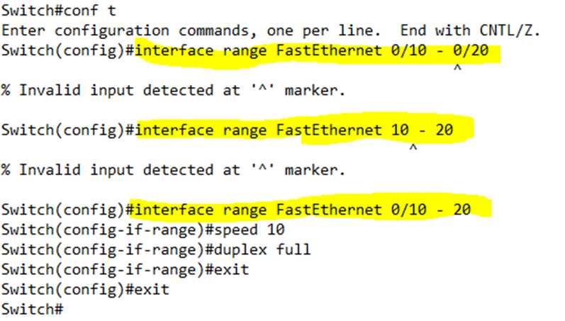
A switch has 24 or 48 interfaces. If I don’t want to configure each one manually, I can type interface range <Interface Type> <first port> – <last port>. Then I can enter the configuration for all the ports in the range at the same time. The switch automatically creates configurations for each interface in the range.
The switch is very picky about this command. A switch will have ports named something like FastEthernet0/1, FastEthernet0/2, FastEthernet0/3, etc. Usually the port numbers start with “0/”. We can normally write FE0/1, FE0/2, FE0/3, etc. We could even write F0/1, F0/2, F0/3, etc. and the switch would understand.
If we had a Gigabit Ethernet switch, our ports would be called GigabitEthernet0/1, GigabitEthernet0/2, GigabitEthernet0/3, etc. We can normally write GE0/1, GE0/2, GE0/3, etc. We could even write G0/1, G0/2, G0/3, etc. and the switch would understand.
With this command, we must type the interface type in full, and we must add the “0/” in front of the first port in the range, and we must type the dash with a space before and after it.
If I want to remove a setting from an interface, I must first enter the configuration for that interface. I could also enter a range of interfaces and remove a setting from all of them.
- no duplex – removes the duplex setting
- no speed – removes the speed setting
- no description – removes the description
When two devices are connected and try to auto-negotiate, they choose the best speed that each can handle (10, 100, or 1000 mbps). They also choose the best duplex that both can handle (full or half).
If we configure the speed and duplex manually, auto-negotiation is disabled. What if one device has auto-negotiation and the other device is hardcoded with a specific speed or duplex? The side that has auto-negotiation will default to the slowest speed – 10, 100, or 1000. It will default to half duplex (if the speed is 10 or 100) or full duplex (if the speed is 1000).
If one side is set to 10 mbps full duplex, or 100 mbps full duplex, the switch with auto-negotiation will set itself to 10 half duplex and the link won’t work.
A Cisco switch will always try to detect the link speed and use that. If it doesn’t work, then the switch will default to a speed of 10. A speed of 1000 is always full duplex, so the connection won’t fail if one side is hardcoded for 1000 full duplex and the other side is set to auto-negotiate.
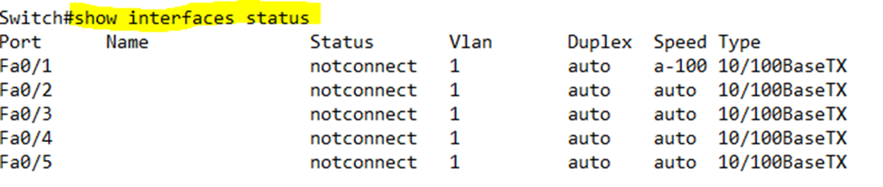
We can type show interfaces status to view the speed, duplex, and connection status of an interface. Notice that the speed says “a-100”. If the interface is set to auto-negotiate, it will display an “a-“ before the speed or duplex.
Going back to my earlier example,
Below is a summary of what the combination of status and protocol means for the connection
| Status | Protocol | Meaning |
| Administratively down | Down | Disabled by the administrator |
| Down | Down | Not connected physically |
| Up | Down | Connected physically, but there may be a communication error |
| Down | Down (err-disabled) | Err-disabled for security reasons (more on this later) |
| Up | Up | Connected and functioning |
When the status is up and the protocol is up, the interface is working. We might say that the interface is “up/up”, or “up and up”. It is common to write the interface status and protocol as status/protocol.
If we want more information about an interface, we can type show interface. What can we learn from the show interface command?
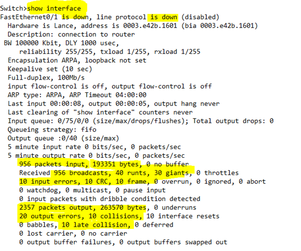
- Speed and duplex of the interface
- Whether the speed and duplex are set automatically
- Statistics
- Packets input – number of packets (frames) received on the interface
- Packets output – number of packets (frames) sent on the interface
- Error Statistics
- Runts – number of frames that arrived too small. Runts are usually due to collisions
- Giants – number of frames that arrived too big.
- CRC – number of frames that did not pass the FCS (Frame Check Sequence). CRC errors could be caused by a bad cable.
- Frame – number of frames that arrived in an illegal format.
- Errors – total number of frames that arrived as runts, giants, or with CRC or other errors.
- Output Errors – total number of frames that could not be forwarded due to an error
- Collisions – total number of collisions that happened while the interface was forwarding a frame
- Late Collisions – total number of collisions that happened after the 64th byte. If the duplex settings on both devices (the switch and whatever is connected to the switch) match, there shouldn’t be any late collisions because they will be detected.
Okay, now we can get to the real topic of VLANs. Remember that on a typical network, every device connects to a switch, kind of like the one in the photo below?
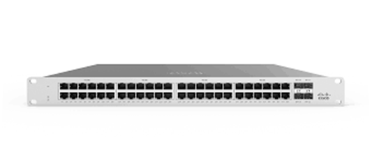
All these devices make up the LAN (Local Area Network). That makes the entire switch was a broadcast domain – if I send a broadcast frame from one device, it is broadcast to every device connected to the switch.
What if we wanted to plug a bunch of devices into the switch but we didn’t want them to see each other’s traffic? For example, we have some surveillance cameras on our network but we don’t want any random users to access them.
We could create a VLAN or Virtual Local Area Network. A VLAN segments the broadcast domain into multiple domains. Each port on the switch is assigned to a single VLAN. Whatever device we plug into the switch assumes the VLAN configured on its port.
For example, we create a VLAN and call it VLAN 20. Ports 10 through 19 are assigned to VLAN 20. Now any device that is connected on ports 10 through 19 are on VLAN 20 and can communicate with each other. If we connect a device to Port 30, it won’t be able to communicate with the devices connected on Ports 10 through 19.
If a device connected on Port 10 for example sends a broadcast message, the switch doesn’t flood that message on all its ports – only on Ports 10 through 19. That is because the VLAN is also a broadcast domain.
The benefit of VLANs is clear: without VLANs, we would have to build a different physical network for each set of devices that we wanted to keep separate. That may not be physically possible in a large network or in an older building.
- We are reducing the amount of work that the switch must perform, because each broadcast domain becomes smaller
- We are improving security because less hosts can see broadcast data
- We can increase security by separating users and other types of devices into different VLANs
Simple switches do not support VLANs. These are commonly known as unmanaged switches. On an unmanaged switch, all the ports belong to VLAN 1 and there is no option to add additional VLANs.
On a managed switch, the default VLAN is VLAN 1, but we can create additional VLANs.