
2.4 Configure and verify (Layer 2/Layer 3) EtherChannel (LACP)
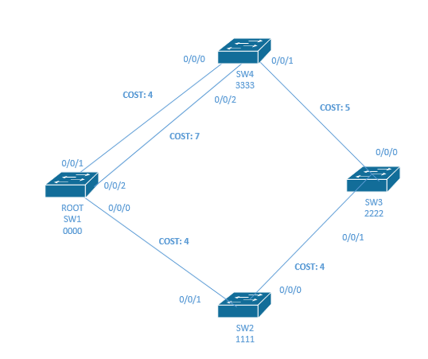
Remember that I had two links between SW1 and SW4. If they were the same speed, I could combine them with a tool called EtherChannel. Then the switches pretend that both links belong to the same physical interface. This lets us double our capacity instead of turning one link off. We don’t have to worry about STP, because even if one link fails, the traffic continues through the other links.
EtherChannel is also known as PortChannel or Channel-Group.
To configure EtherChannel on a set of interfaces, we first choose a channel number, and then enter the configuration for the channel by typing interface port-channel <channel-number>. If the channel didn’t previously exist, the switch will create it. We don’t need to manually create a channel – adding it to a physical interface will automatically create it.
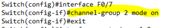
We add each interface to the EtherChannel by typing channel-group <channel number> mode on. For example, I added channel group two to Port 7.
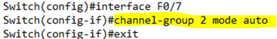
We can configure the channel-group mode by typing channel-group <channel number> mode [auto | desirable | active | passive | on].
There are two EtherChannel protocols – Cisco’s Port Aggregation Protocol (PAgP) or the Link Aggregation Control Protocol (LACP). PAgP has two modes – desirable and auto. LACP has two modes – active and passive.
- Auto – the port acts passively. It does not negotiate an EtherChannel with another switch, but it does listen for EtherChannel messages from other switches. It will establish an EtherChannel upon receipt of an EtherChannel message. This method uses PAgP.
- Desirable – the port acts actively. It sends EtherChannel messages to other switches and attempts to activate an EtherChannel. This method uses PAgP.
- Active – the port acts actively. It sends EtherChannel messages to other switches and attempts to activate an EtherChannel. This method uses LACP.
- Passive – the port acts passively. It does not negotiate an EtherChannel with another switch, but it does listen for EtherChannel messages from other switches. It will establish an EtherChannel upon receipt of an EtherChannel message. This method uses LACP.
- On – the port is configured manually. It operates as an EtherChannel and does not negotiate with the other switch.
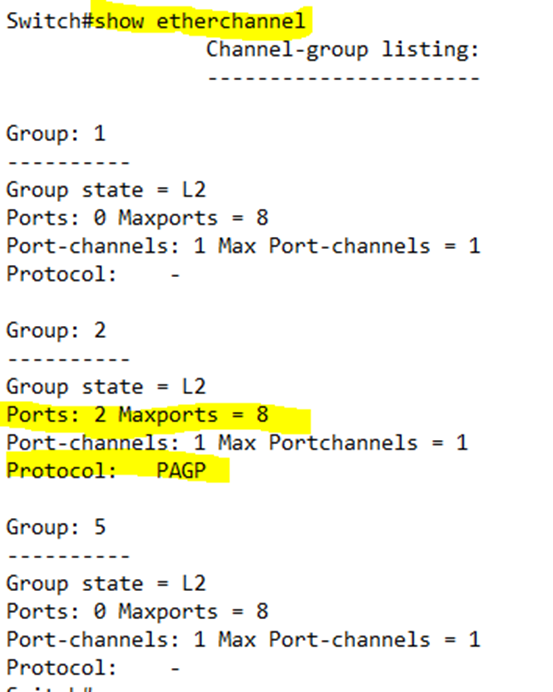
We verify the EtherChannel’s settings through the following commands
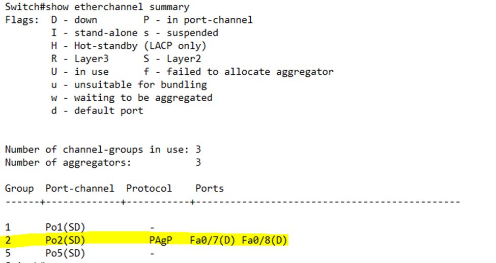
- show etherchannel gives us a list of EtherChannels activated on the switch
- show etherchannel summary provides this information in a summary table. In our example, it shows us that Port Channel #2 is activated on ports FastEthernet0/7 and FastEthernet0/8.
For EtherChannel to function properly, the following settings must be the same on all the interfaces in the channel
- Speed
- Duplex
- Access – all interfaces must be access or all interfaces must be trunks
- VLAN (for an access port) or allowed VLANs (for a trunk)
- Native VLAN for a trunk
- STP interface settings
If the settings are not the same, the channel will not work. If a PortChannel is disabled due to an error, its physical ports will also be error disabled.
Once we’ve established an EtherChannel between two switches, how does a switch decide which frame should be sent out of which physical interface? We call this load balancing. There are several criteria that the switch can use. We can configure it by typing port-channel load-balance <method>. The method to use in the command is in brackets below.
- Source MAC (src-mac)
- Destination MAC (dst-mac)
- Source & Destination IP (src-dst-mac)
- Source IP (src-ip)
- Destination IP (dst-ip)
- Source & Destination IP (src-dst-ip)
- Source TCP/UDP Port (src-port)
- Destination TCP/UDP Port (dst-port)
- Source & Destination TCP/UDP (src-dst-port)
The main goal of load balancing is to prevent frames from arriving in a different order from how they were sent. We must think about the type of traffic flowing over each VLAN and choose the best load balancing option. For example, a video feed coming from a surveillance camera and travelling to a DVR will have the same source address. The different video packets should all take the same route.
We can ask the switch for its opinion as to what route it would send the traffic on by typing test etherchannel load-balance interface <etherchannel number> <load balance method>.
For example, if I wanted to know how the EtherChannel would send traffic to a device with the MAC address AA:BB:CC:DD:EE:FF, I could write test etherchannel load-balance interface 1 mac AABBCCDDEEFF.
The switch responds that it would choose Port 7 (FastEthernet0/7)
