2.5 Describe the need for and basic operations of Rapid PVST+ Spanning Tree Protocol and identify basic operations
2.5.a Root port, root bridge (primary/secondary), and other port names
2.5.b Port states (forwarding/blocking)
2.5.c PortFast benefits
I drew this network with redundant links. Traffic from Switch 1 to Switch 3 can pass through either Switch 4 or Switch 2.
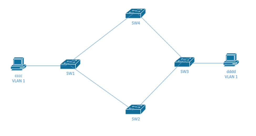
How does traffic get from “cccc” to “dddd”? It must go through SW1, and then either SW2 or SW4, and then SW3.
What would happen if SW1 doesn’t know about “dddd” – it doesn’t have “dddd” in its MAC address table? It would flood the frame onto Switch 2 and 4. Switches 2 and 4 would send the frame to Switch 3. Switch 3 would send the frame from Switch 2 to Switch 4 and the frame from Switch 4 to Switch 2. It also sends the frame to “dddd”. Switches 2 and 4 would send to Switch 1. This would go on forever (or until one switch learned the MAC address of dddd). This is called a broadcast storm, and it is not good.
That frame has a from address of “cccc”, and it is addressed to “dddd”, but it keeps coming in through different ports. Switch 1 sees it come in from the port connected to “cccc” and then from the port connected to SW4 and then from the port connected to SW2. Each time, it updates its MAC Table with the source of the packet. This might happen hundreds of times per second. So the switch doesn’t know where “cccc” is connected anymore. This is called MAC Table Instability.
The result of this mess is that “dddd” receives multiple copies of the same frame. This is called multiple frame transmission.
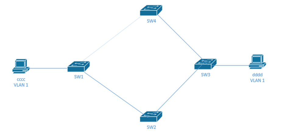
We should turn off the connection between Switch 1 and Switch 4 (or between Switch 1 and Switch 2). Now we can still get traffic to all the devices and we don’t have any risk of creating a loop.
How do we decide which switch link to turn off? How do we identify redundant links like this in a large network?
We use a Spanning Tree Protocol (STP) or Rapid STP (RSTP). How does it work? The switches figure out how many connections they have amongst themselves. If two switches discover that they have multiple links (physical connections between themselves), they turn all of them off except for one. STP works on small networks of just two switches and large networks that could have dozens or hundreds of switches.
- First all the switches pick one switch to be the “root bridge”. The root bridge is switch with the smallest bridge ID (BID).
The bridge ID is 8 bytes- A 2-byte priority field – an administrator can manually configure the priority field
- A 6-byte MAC address – this ensures that each switch has a unique bridge ID
The root bridge is the switch with the lowest priority. If multiple switches have the same priority, then the switches choose the switch with the lowest MAC address.
- The switches establish the STP by communicating through Bridge Protocol Data Units (BPDUs).
- They send Hello messages, which include
- The bridge ID of the sender
- The bridge ID that the switch believes is the root. I said believes. When the network first starts up, every switch thinks that it is the root, because none of the switches know about the other switches’ bridge IDs.
Each time a switche receives a Hello message from another switch it decides whether to continue believing it is a root or whether another switch should be the root.
If a switch receives a hello message from a switch with a lower bridge ID, it recognizes that switch as the root instead of itself – this other switch may not be the root either; it just has a lower bridge ID. It passes this information to other switches through subsequent Hello messages.
Eventually, all the switches figure out which one is the root.
- How much it costs the sending switch to access the root switch.
- The timer value
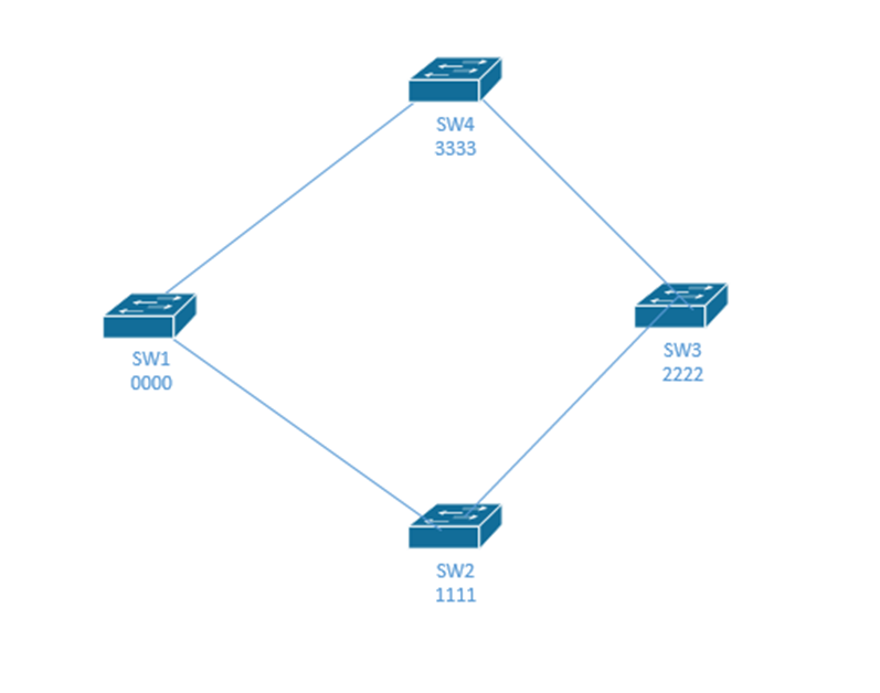
- Consider this network with four switches. The switch BIDs are 0000, 1111, 2222, and 3333. When this network starts up, every switch thinks that it is root.
SW1 is the true root.
SW1 learns about SW2 and SW4, but stays as root because it has the lowest ID.
SW2 learns about SW1 and SW3, and decides that SW1 is root.
SW4 learns about SW1 and SW3, and decides that SW1 is root.
SW3 learns about SW2 and SW4, and decides that SW2 is root, which is wrong.
SW2 and SW4 tell SW3 that they think SW1 is root. SW3 checks and realizes that SW1 has a lower BID than SW2, so it now agrees that SW1 is root.
Now all the switches know that SW1 is the root. - The interfaces on the root bridge are all set to forward traffic. They are in the forwarding state.
- Each of the remaining switches figures out how it is connected to the “root”. If a switch has multiple connections to the root, it assigns a cost to each one. What would it cost me to get my traffic back to the root switch? The greater the bandwidth, the lower the cost. For example, a 100 Mbit/s link costs “19”, while a 1 Gbit/s link costs “4”. This is called the root cost. The switch turns off the most expensive links. The port connected to the link that stays on is called the root port.
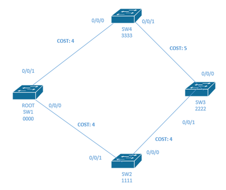
- For example, SW1 is the root switch. Each of the other switch figures out the cheapest way to get the root.
SW4 and SW2 can get to the root directly. The cost is 4.
If SW4 wanted to go through the long route (through SW3 and SW2), it would cost 13 – that is the cost of all three links (5 + 4 + 4). If SW2 wanted to go through the long route (through SW3 and SW4), it would cost 13 – that is the cost of all three links (5 + 4 + 4).
Thus, SW4 keeps port 0/0/0 in a forwarding status, and SW2 keeps 0/0/1 in forwarding state.

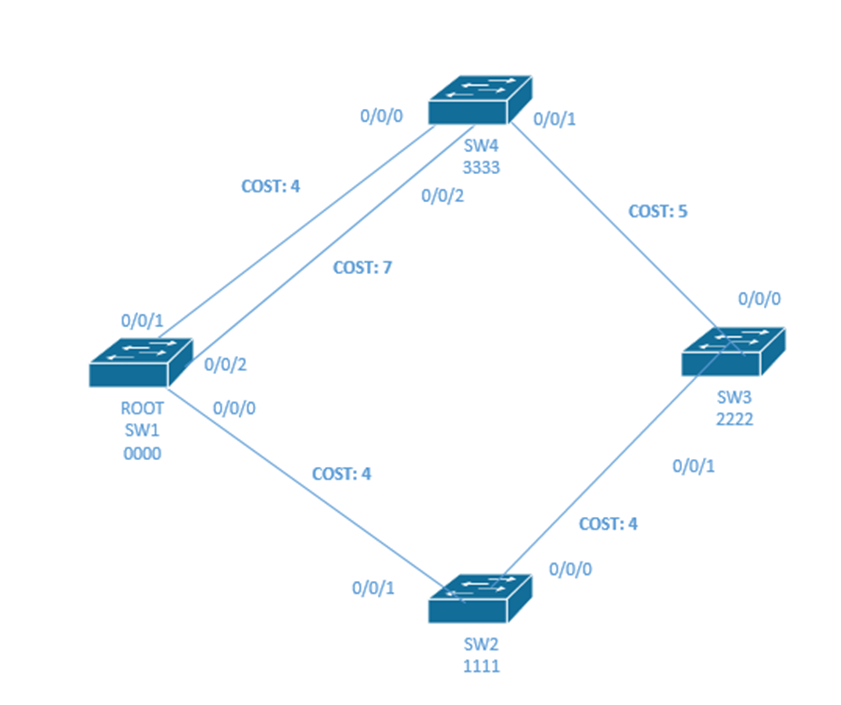
- What if SW4 had two physical links to SW1? It would choose the one with the lowest cost (the one with cost of 4 and turn off the other port). That would mean that 0/0/2 on SW4 is set to a blocking state.
If the links had the same cost, it would keep the one connected to the interface with the lowest port number. - STP only worries about ports that are working – where the status is up and up. If the cable is unplugged or if the port is administratively down, then STP doesn’t consider that port in determining whether to use it.
- Remember that the topology can become complicated. There may be several switches between an edge switch and the root switch. Thus, the pathway to the root may involve several links, each of which has its own “cost”.
- Switch 3 needs to figure out a cost. It can go through Switch 4 or Switch 2. The cost to get to the root through switch 2 is 8, and the cost through switch 4 is 9. Therefore, SW3 turns off the link between itself and SW4 (it sets port 0/0/0 to a blocking state) and sends traffic through SW3.
How did SW3 know the root cost that SW2 and SW4 have with SW1? From the Hello message. SW4 and SW2 tell SW3 what their root cost is. SW3 simply adds their root cost to its root cost to obtain the total root cost.
What if there is a tie in the root cost?- The switch chooses a neighbor with the lowest BID
- If there is a tie in BIDs, then it chooses the neighbor with the lowest port priority
- Finally, if there is still a tie, it chooses the neighbor with the lowest physical interface number
- When there are multiple switches fighting for a connection to the root, the switch with the lowest cost connection is called the designated switch and the port that it uses to connect to the pathway to the root is called the designated port.
SW3, port 0/0/1 is the designated port and SW2 is the designated switch, because SW2 provides SW3 with the lowest cost pathway to the switch, and SW3 is connected to SW2 through port 0/0/1. - If multiple pathways have the same cost, then the switch chooses the pathway containing the neighboring switch with the lowest bridge ID.
- A port can have any of the following statuses:
- Blocking. The switch determined that this port will cause a loop. It does not send or receive any traffic on this port, except for BPDU data.
- Listening. The port does not transmit data, nor does it learn MAC addresses of devices connected to it.
- Learning. The port does not transmit data, but it still learns MAC addresses of devices that could be connected to it.
- Forwarding. A normally operating port. All data is transferred.
- Disabled. The port was manually turned off or turned off due to a security incident. We’ll talk about security incidents later. No data is transferred, not even BPDU data, and the switch does not learn MAC addresses of devices connected to it.
- The switches continually revaluate their connections and recalculate the cost of each link. Switches exchange Bridge Protocol Data Units every two seconds. In case a switch or link fails, the other switches can quickly re-establish a connection.
- The switches also continually test their data links. If a link fails, the switch sends traffic over another link. If a less expensive link starts working again, the switch returns to sending traffic over it. A switch tests its link by sending a “hello” message every two seconds. If the switch does not receive a reply after three subsequent “hello” messages (six seconds), it assumes that the link is defective and chooses a new link.
Once STP is established, only the root switch can generate a hello. The other switches only forward the hello.
In summary, the following ports are in forwarding mode
- All the root switch ports are forwarding.
- Each non-root switch port with the lowest cost in reaching the root is forwarding.
- Each designated port is forwarding.
Any switch port that is not in forwarding is in blocking mode.
Going back to our timers
| Hello | Every two seconds, the root switch sends a Hello message. The other switches expect to receive the Hello message every two seconds. |
| MaxAge | The MaxAge timer is ten times the Hello timer (or 20 seconds). If a switch doesn’t receive a Hello message in the MaxAge time (20 seconds), it assumes that the root switch failed, and decides to change the STP |
| Forward Delay | The forward delay is how long a switch takes to change from blocking mode to forwarding mode, as we will see |

Remember that SW1 is the root, SW2 connects to SW1, SW4, connects to SW1, and SW3 connects to SW1 through SW2 because that is the route with the lowest cost.
If SW4 failed, nothing would change in STP because no other switches connect to it.
If SW2 failed, after 20 seconds, SW3 would realize that it hasn’t received any Hello messages. It would start listening for Hello messages again and would send traffic through SW4. That means port 0/0/0 on SW3 would become a forwarding port.
A switch can change a port’s status from forwarding to blocking immediately. But there is a 30 second delay in changing from blocking to forwarding. Why? The switch needs need to make sure it made the correct choice so that loops are not created.
There are two statuses that exist between blocking and forwarding.
- Listening – the switch is listening for traffic. The switch clears its MAC address table of any entry that does not send it traffic during this time. It does not forward any traffic and it does not add any new entries to the MAC address table.
- Learning – the switch continues to listen for traffic and adds new MAC address entries. It does not forward any traffic.
The switch remains in each state for 15 seconds. That means the total delay is 50 seconds (20 seconds waiting for a Hello message that never arrives, 15 seconds in the Listening state, and 15 seconds in the Learning state).
A better system is called Rapid Spanning Tree Protocol (RSTP). RSTP is an improvement over the original STP protocol. It is the same, except for the port states. In RSTP, there are three port states
- Discarding. The port does not send or receive any traffic. This is the same as blocking.
- Learning. The port does not send any traffic, but it does learn MAC addresses of devices connected to it.
- Forwarding. The port is sending and receiving traffic normally.
The benefit of RSTP is that we don’t need to wait to change the root port or forwarding state. In RSTP, each switch designates an alternate port that it can use when the root port fails, and a backup port it can use when the designated port fails. If a switch fails, the other switches activate their alternate/backup ports as necessary.
Each switch generates its own Hello message instead of forwarding Hello messages from the root switch.
How does it work?
- The switches elect the root switch the same way as STP
- Each switch selects the root port the same way as STP
- The alternate port is a port on a switch that is connected to the root. A switch might have two connections to the root switch – a root port and an alternate port.
- If the root connection fails, the root port becomes disabled, and its state is changed to discarding
- The alternate port immediately becomes the root port and its state is changed to forwarding
- A switch that changes its topology tells other switches so that they can flush their MAC address tables. We don’t waste time with the learning/listening states.
RSTP Port Definitions
- Point-to-Point Port – a port that connect two switches together
- Point-to-Point Edge – a port that connects a switch to an endpoint (like a PC, printer, or VoIP phone)
- Shared Port – a port that connects a switch to a hub
How do we configure STP? We don’t. STP works on a Cisco switch by default. But we could change the priority of a switch or the cost of a link.
Below is the cost of each link speed. The cost was updated in 2004 to accommodate speeds of 100 Gbps and 1 Tbps.
| Speed | Cost | Cost (after 2004) |
| 10 Mbps | 100 | 2,000,000 |
| 100 Mbps | 19 | 200,000 |
| 1 Gbps | 4 | 20,000 |
| 10 Gbps | 2 | 2000 |
| 100 Gbps | N/A | 200 |
| 1 Tbps | N/A | 20 |
The switch determines the cost based on the actual speed of the port, not its maximum supported speed.
Remember that I had two links between SW1 and SW4. If they were the same speed, I could combine them with a tool called EtherChannel. Then the switches pretend that both links belong to the same physical interface. This lets us double our capacity instead of turning one link off. We don’t have to worry about STP, because even if one link fails, the traffic continues through the other links. We will look at EtherChannel in the next chapter.

We can also turn on PortFast when using STP. It is on by default in RSTP. PortFast allows a port to immediately switch from blocking to forwarding, without entering the listening/learning states. We shouldn’t use it on any port that is connected to a switch or hub or we could create a loop.
Why do we need PortFast? When an end user device connects to the switch, the switch must wait a few seconds to make sure that the port is a designated port. That increases the amount of time it takes for a user to establish a connection. If we turn on PortFast, an end user can connect to the switch faster.
What happens if a hacker connects a switch to a port on our network, and gives his switch a lower priority than that of the switches on the existing network? He could create a root switch and steal all the traffic. We can stop him with BPDU Guard. BPDU Guard is added to any port that should only be an access port. If the switch receives a BPDU message on a port with BPDU Guard, it will automatically disable the port.
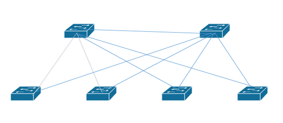
Let’s go back to my earlier network where I had core switches at the top (the spine leaf). I should make the core switches the root switches.
If this network had VLANs, it could get complicated. What if the pathway from some edge devices on some VLANs was cheaper than the pathway from other edge devices on other VLANs? Maybe the STP route decided that the best route for one VLAN is different from the best route for another VLAN. What do we do?
We could create multiple spanning trees
- Spanning Tree Protocol and RSTP are open protocols each of which supports only one tree
- PVST+ or Per-VLAN Spanning Tree Plus protocols allows us to create a separate spanning tree per VLAN
- Rapid PVST+ also allows us to create a separate tree per VLAN
- MSTP or Multiple STP is an open protocol, but does not necessary require one tree per VLAN
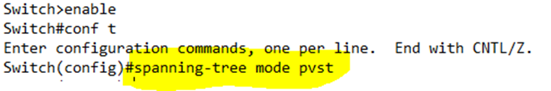
We can choose the STP mode that we want our switch to use by typing spanning-tree mode [pvst | rapid-pvst | mst]
For example, I have chosen PVST+
Remember how our bridge ID was a 2-byte priority and a 6-byte MAC address? Well actually, the bridge ID is a 4-bit priority (half a byte) and a 12-bit (1.5 bytes) system ID extension, which contains the VLAN ID, and the 48-bit (6-byte) MAC address.
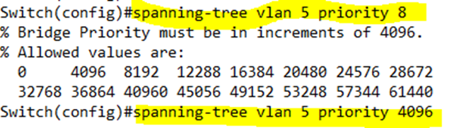
If I want to configure a priority for a specific VLAN, I type spanning-tree vlan <VLAN number> priority <priority>. The priority must be a multiple of 4096, between 0 and 65, 535. I tried to give it a priority of 8, but the switch rejected the command.
If you have a large network and any of your switches could be elected to be the root switch, then your LAN probably sucks. Instead, you should choose two switches – a primary switch and a secondary switch – that are good candidates for acting as the root switches.
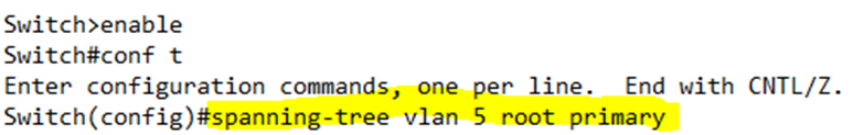
We can configure a primary switch by typing spanning-tree vlan <VLAN number> root primary, and on the secondary, configure it as spanning-tree vlan <VLAN number> root secondary. In the below example, I sent my switch as primary for VLAN 5.
Once configured, each switch chooses a good priority value and configures itself through the spanning-tree vlan <VLAN number> priority <priority> command. How?
- If the current root has a priority that is higher than 24,576, the primary switch chooses 24,576 as its priority
- Otherwise, the primary switch chooses a number that is 4096 less than the current root’s priority.
- The secondary switch chooses a priority of 28,672.
- This command usually works because, by default, switches choose a priority of 32,768. If all the switches on the network have a priority of 32,768, then the secondary switch now has the second lowest priority, and the primary switch has the lowest.
What is the difference between RSTP and RPVST +?
- RSTP can support one tree, but RPVST+ has one tree per VLAN
- RSTP broadcasts one set of BPDU messages but RPVST + broadcasts one set per VLAN
- RSTP sends messages in the native VLAN of the trunk port but RPVST + sends each message inside the corresponding VLAN
- RSTP and RPVST+ both use a 16-bit priority, but RSTP sets the VLAN portion to 0.
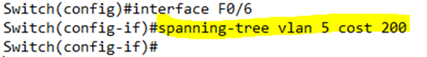
Since we can set a different priority per VLAN, it follows that we can also set an interface cost per VLAN. We type spanning-tree vlan <VLAN number> cost <cost>. We must configure this command on each interface separately. In the below example, I set Port 6’s VLAN 5 cost to 200.
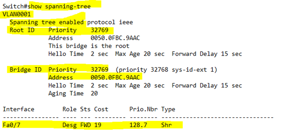
We can verify the spanning tree settings by typing show spanning-tree. In our example, the switch is listing spanning tree data for VLAN 1.
- Under Root ID, it tells us that the Root ID on the network has a priority of 32769. It also tells us that the MAC address of the Root is 0050.0FBC.9AAC. In this case, our switch is the root – it says, “This bridge is the root”.
- Under Bridge ID, it tells us the priority and MAC address for the current switch. In this case, the current switch is the Root. Therefore, the Root ID and Bridge ID would have the same values.
- The switch also tells us the Hello Time, Max Age, and Forward Delay times.
- The switch lists any interfaces that are in a forwarding state. In this case Fa0/7 is a designated port.