
2.7 Describe physical infrastructure connections of WLAN components (AP, WLC, access/trunk ports, and LAG)
Remember that an autonomous AP can map each BSS (SSID) or WLAN to a VLAN. We connect the autonomous AP to a trunk port on our switch. The autonomous AP must tag each frame with its VLAN.
For example, the Guest Wi-Fi might be VLAN 5 and the Corporate Wi-Fi might be VLAN 10.
If we use a LAP, then we connect it to an access port, because traffic for multiple VLANs can be transported through the CAPWAP tunnel.
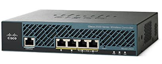
On the physical controller, there are several physical ports
- The Service Port is used for managing the system. We connect this port to an access port on the switch.
- A Distribution System Port handles AP data and AP management traffic. We connect this port to a trunk port on the switch.
We can configure the distribution system ports to operate redundantly in pairs. In each pair, one port is the primary and one is the backup. We can create a Link Aggregation Group or LAG so that multiple ports can act as one larger connection. This allows the WLC and the switch to balance the traffic across multiple cables. Because WLCs don’t have the ability to negotiate an EtherChannel, we must configure the switch ports with an unconditional or always-on EtherChannel configuration. - The Console Port is used to configure the WLC locally.
- The Redundancy Port is used to connect one controller to another for redundancy. This is also known as High Availability.
To map each WLAN to a VLAN, we create a logical interface in the controller. We create one logical interface per WLAN. For each logical interface, we must specify the
- IP Address
- Subnet Mask
- Default Gateway
- DHCP Server IP Address
- VLAN ID. We can assign a VLAN to multiple WLANs.
- Physical port on the WLC. We can assign multiple WLANs to the same physical port.
What kinds of logical interfaces are available on a WLC?
- Management Interface. We only send management traffic over the management interface, such as SSH sessions, Network Time Protocol, user authentication, and logging. We also use this interface to establish tunnels between the LAP and the WLC.
- Redundancy Management. When we have two WLCs working together for redundancy, the active WLC uses the Management Interface, and the backup or standby WLC uses the Redundancy Management Interface. Each interface has a unique IP address.
The primary WLC uses the IP address assigned to the Management Interface, and the backup or standby WLC uses the IP address assigned to the Redundancy Management Interface.
Remember that these are not physical ports – the primary and backup traffic may travel through the same port on each WLC. - Virtual Interface. This is the interface that a client connects to when it obtains a DHCP address or when it needs to authenticate. The client connects to the Virtual Interface’s IP address, and the WLC relays the DHCP or authentication message to wherever it needs to go. Only clients see the Virtual Interface.
We should assign the virtual interface a unique non-routable IP address such as a private IP address. If we have multiple WLCs, we should assign the Virtual Interface in each WLC the same IP address. That way, a client can move from one WLC to another without disrupting its connection. The client will assume that all the different WLCs are the same WLC. - Service Port Interface. This interface is only used by the physical service port and can only be used for managing the WLC.
- Dynamic Interface. The Dynamic Interface connects a WLAN to a VLAN and is therefore used to move user traffic. We must create a different Dynamic Interface for each WLAN. Each Dynamic Interface must have its own IP address.