
3.1 Interpret the components of routing table
3.1.a Routing protocol code
3.1.b Prefix
3.1.c Network mask
3.1.d Next hop
3.1.e Administrative distance
3.1.f Metric
3.1.g Gateway of last resort
For a while I’ve been talking about switches and how we forward traffic on a local network. Let’s think about routers now. A router forwards traffic from one local network to another.
I mentioned earlier that we can connect a router to another router via an Ethernet WAN or a serial connection (which users HDLC).
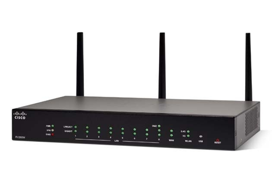
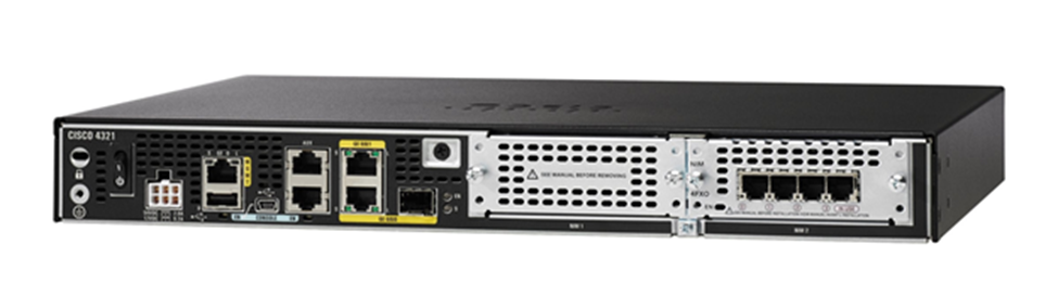
You will see three types of Cisco routers
- A SOHO (Small Office Home Office) router. This type of router offers basic connectivity to commercial broadband internet. It will also offer basic DHCP, firewall VPN features. It may not support WANs, HDLC, or MPLS technology.
- A standard Enterprise router. This type of router supports all the major enterprise features including VPN, WAN, DHCP. It will certainly support multiple WAN or serial connections.
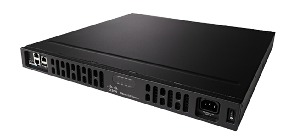
- An ISR (Integrated Services Router). The Cisco ISRs offer Enterprise features, but they also offer advanced features such as VoIP management, advanced firewalls, and threat detection. An ISR’s hardware can be upgraded – we can install cards to provide the router with additional interfaces so that it can connect to a T1, a CSU/DSU, analog phones, etc.
How do we connect a router? What are the basic steps?
- Connect the router’s LAN port to the switch
- Connect the router’s WAN to an ISP interface (like a modem or CSU/DSU). Connect the Ethernet WAN if you have one
- Connect to the console port
- Power on the router
- Configure the router. Specifically, we should configure the router interfaces, the routing protocol, and the security settings. If we have a router with advanced features, we should configure those as well.
I already talked about the basic configuration of a router or switch in section two. Some ideas that are the same on a Cisco router and on a switch
- User, enable and configure terminal modes, and the process of logging in to them
- Console port connection and terminal settings
- Ability to access the router through Telnet or SSH
- Router hostname configuration
- Router interface configuration, including the speed and duplex
- Command to shutdown an interface or to turn it back on (no shutdown)
- Running and start up configuration and the ability to save the running config to the start up config
- Memory types and purposes
What is different about a router?
- A router does not have VLANs. We do not configure VLANs on a router.
- A router interface can be configured with a static IP address or a DHCP address. A switch port interface does not have an IP address
- All router interfaces, by default, are shutdown. They must be turned on manually.
- A router may have an auxiliary port to connect to a remote modem
- A router, by default, does not allow access via Telnet or SSH. It must be manually enabled.
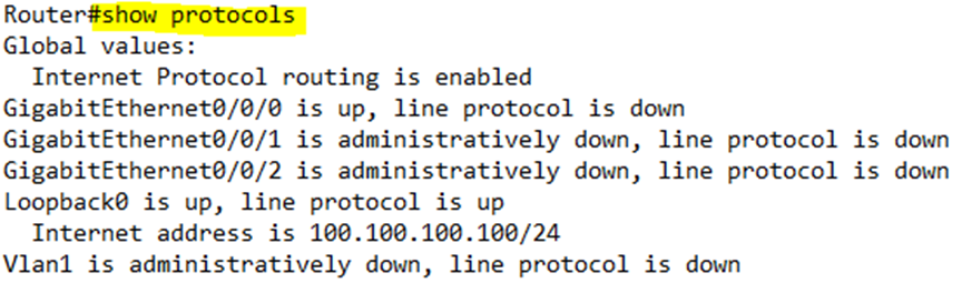
- A router uses the show ip interface brief to tell us about the interfaces and their status.
Let’s look at the show ip interface brief command some more.
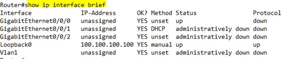
- Line Status or Status tells us if the physical layer is working (if the cable is plugged in)
- Administratively down means that the interface was shut down. By default, an interface is shut down unless we turn it on.
- Down means that the cable is unplugged or that there is some other communication issue on the physical layer
- Protocol Status or Protocol tells us if the Layer 2 is working (if the device is communicating)
- If the Line is Up and Protocol is Down, then there is probably a speed or duplex mismatch between the router and another router
It’s not possible for the Protocol to be up and the Line Status to be down.
We can also type show protocols to view this data.
How do we configure a router interface? From the configure terminal, we type interface <interface name>. We can configure the following additional settings on an interface
- ip address <IP address> <subnet mask> – most router interfaces will be configured statically, but if the router interface will receive an IP address via DHCP, we don’t need to enter this command.
- no shutdown – by default, an interface will be shutdown. We must turn it on so that we can use it.
- description <name> – this command is optional and allows us to give the interface a memorable description
If we type show ip route, the router will print a list of routes that are configured on it.
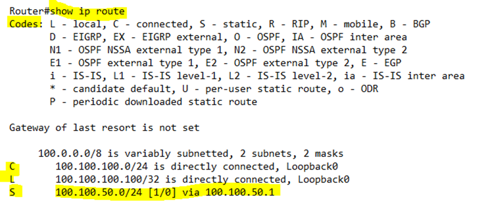
I will explain some terms briefly now, and we will learn more about them in the coming sections. Each time a router receives a packet, it needs to decide where to send it. How? It checks the routing table. The routing table has a list of routes.
Each route has a list of destination networks and where traffic addressed to that network should be sent. For example, a route might say traffic addressed to network 10.10.0.0/24 (the range would be 10.10.0.0 to 10.10.0.255) should go to router 10.10.0.1. If our router receives a packet addressed to 10.10.0.50, it would check the route table and realize that it should be sent to 10.10.0.1.
In front of each route is a letter or a code. The router displays a legend that tells us what each code means. For example, L means local, and S means static. This code is better known as the routing protocol code. It tells us how the router learned the route.
Next to the code is an IP address (known as a prefix) and a subnet mask (the slash followed by a number). Together, they identify a network. For example, 100.100.100.0/24 identifies the network with the range of IP addresses from 100.100.100.0 to 100.100.100.255. The router knows that any packet addressed to an address within this range must follow what this route tells us.
The last route on the list says that it is “via 100.100.50.1”. That means that traffic in that route should be sent to the next router, which has an address of 100.100.50.1. This router is known as the next hop router. When our router sees a packet addressed to a host in the 100.100.50.0/24 network, it sends it to the 100.100.50.1 router.
We might have multiple routes to the same destination network. The router might know about a route because it is directly connected, because an administrator programmed it, or because it learned it from another router. When there are multiple routes, which one should the router use?
In brackets after the network name is the number “[1/0”]. The first number is the administrative distance. The administrative distance tells us how much the router trusts the route. The lower the number, the more the router trusts the route. The router will choose the route that it trusts the most.
The second number is the metric. The metric tells us how efficient the route is. The longer the route, the higher the metric. Again, the router will choose a route with the lowest metric.
When the router receives a packet addressed to a network, but does not have a route to that network, it sends the packet to the gateway of last resort. We must manually configure the gateway of last resort on the router. In my example, the gateway of last resort is not set.
A route will only appear in the routing table if the interface that it is connected to is up and up (the status and line protocol are up). When the interface goes down, the router will remove its applicable routes from the routing table. When the interface comes back up, the router will return the applicable routes to the routing table.
Let’s review how a router learns the different routes so that it can forward packets
- Connected Route – the router automatically learns about other routes that are directly connected to it. Each router will have at least two directly connected routes – one to its LAN and one to its WAN.
- Static Route – an administrator can manually program the router with a route. This is known as a static route.
- Routing Protocol – the router learns routes to far away networks from other routers that are directly connected to it. It does so through a routing protocol. There are several types of routing protocols and we will learn how they work.
Remember that when a device wants to send a packet, it asks if the destination IP address is in the local subnet (the LAN). If so, it sends the packet to the local switch. It uses ARP to find the MAC address of the destination device, and the switch forwards it. If not, then it sends the packet to the router. It encapsulates the packet in an Ethernet frame and addresses that frame with the router’s MAC address.
But what does the router do exactly when it receives a packet?
- First the router makes sure that the packet arrived without error.
- It verifies that the packet is actually addressed to the router (it is possible for the router to receive packets through a broadcast that are not addressed to it)
- The router deencapsulates the old frame headers revealing the IP packet inside
- The router looks up the destination in the routing table, based on the IP address
- It checks the ARP table for the destination router’s MAC address. If it is not there, it requests it through ARP
- Encapsulate the frame with the destination router’s MAC address and sends the frame
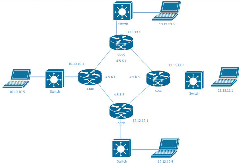
The computer on the left has an IP address of 10.10.10.5 and it wants to send a message to the computer on the right, which has an IP address of 11.11.11.5. Our router has a MAC address of aaaa, and the computer on the right is connected to a router with a MAC address of cccc.
Computer 10.10.10.5 prepares an IP packet addressed to 11.11.11.5. It realizes that 11.11.11.5 is not on its local network. Thus, it encapsulates the IP packet into a frame addressed to its local router’s MAC address (aaaa). The router aaaa receives the packet and checks its routing table.
Notice that each router has a local interface in its subnet (with a local IP address), and a WAN interface in the wan subnet (that starts with 4.5.6). When a device wants to talk to its local router, it uses the local interface. When a router wants to talk with another router, it uses that router’s WAN interface.
Maybe router aaaa has the following routes
- 10.10.10.0/24 via the local interface. This is the directly connected local network on the left.
- 12.12.12.0/24 via router 4.5.6.2. This router is directly connected, so our router learns it automatically.
- 13.13.13.0/24 via router 4.5.6.4. This router is also directly connected, so our router learns it automatically.
- 11.11.11.0/24 via router 4.5.6.2. This router is not directly connected, so our router learns it from router bbbb (4.5.6.2).
- 11.11.11.0/24 via router 4.5.6.4. Our router also learns this route from router dddd (4.5.6.4).
The router knows that it can send the packet to the router with the IP address 4.5.6.2 or 4.5.6.4. Let’s say that the route through 4.5.6.2 is better, so the router chooses that one.
It sends an ARP message to router 4.5.6.2 and learns that its MAC address is bbbb. It encapsulates the packet in a frame with the destination MAC address bbbb, and sends it to bbbb.
The router bbbb receives the frame and dencapsulates it. The router checks its routing table and sees that it has a directly connected route to network 11.11.11.0/24. Using the same process, it obtains the MAC address to the router 11.11.11.1, which is cccc. It encapsulates the packet with an Ethernet frame and sends it to cccc.
Router cccc receives the frame and dencapsulates it. The router checks its routing table and sees that 11.11.11.5 is in the local network. It encapsulates the frame with the MAC address of the computer 11.11.11.5 and sends it to the computer.
We can configure an interface on a router by entering the interface configuration. There are several items we can configure
- mac-address <MAC address>. This sets a configured MAC address for an interface. It is optional because the interface will have a default MAC address from the factory that the router can use. If our interface did not have a MAC address, the router would use the MAC address of the lowest-numbered interface.
- ip address <IP address> <subnet mask> allows us to set an IPv4 address on the interface
- ip address dhcp allows the router to learn the IPv4 address via DHCP
- ipv6 address <address/prefix length> eui-64 allows the router to generate an EUI-64 IP address on the interface. A Cisco router will understand the abbreviated address. In other words, we can type ipv6 address <address>/64 eui-64
- ipv6 address dhcp allows the router to learn the IPv6 address through DHCP
- ipv6 address autoconfig allows the router to use the SLAAC to configure an IP address
- ipv6 address <address> link-local tells the router to use a specific link-local address (instead of automatically generating an IPv6 address). A router will automatically generate a link local IP address on any enabled interface. It’s possible to create a WAN link with only IPv6 link-local addresses.
- If a host needs to contact a service but doesn’t know the IP address of the router that offers it, it sends a message to a single Anycast address. Upon receipt of a packet addressed to an Anycast address, the network forwards it to a single router that offers the applicable service (even though there may be many). Routers forward the Anycast packet until it reaches a router that can accept it. We can configure an Anycast address by typing ipv6 address <IP address> anycast.
A router won’t support IPv6 out of the box. We must enable it by typing ipv6 routing in global configuration mode.
CCNA doesn’t mention the ping or tracert commands explicitly, but they are important to know.
The ping command tells us if a host is reachable. Ping uses ICMP or Internet Control Message Protocol. The formal name for ping is
- ICMP echo request – this is the packet that we send to the host
- ICMP echo response – this is the packet that the host sends back
ICMP does not use TCP or UDP. It is its own Layer 3 protocol. ICMP works on most operating systems – Windows, Mac, UNIX, and it works inside Cisco IOS devices.
When we send a ping, the ping command uses default parameters. We can modify the following parameters
- How many times we should send the ping request
- Whether we shouldping an IP address or a hostname (if we ping a hostname, the operating system will find the IP address via a DNS lookup and then ping that)
- How long we should wait until we assume that the ping has timed out
- How big should each packet be
- Whether we should send the pings continually or just a few times
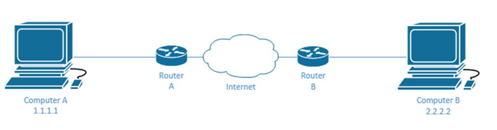
If Computer A can’t reach Computer B, one of the first troubleshooting steps we can take is to ping Computer B from Computer A. There are many issues that can cause a host to become unreachable, but we should try to ping it first. If we are in a remote location and can’t connect to Computer A to perform the ping, we might log in to Router A via SSH and ping Computer B from inside Router A.
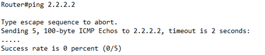
By default, a Cisco router will send five pings. If the router does not receive a reply within two seconds, it assumes that the ping timed out (failed).
An example of a failed ping is below.
An example of a successful ping is below.
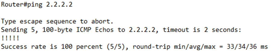
The first time we ping a remote router that we haven’t connected to before, we usually receive a success rate of four out of five. Upon receipt of the first ping message, the remote router will check its ARP table. It won’t find the MAC address of the router that initiated the ping, and so it will be unable to reply. The remote router will an ARP request too learn the local router’s MAC address. Upon receipt of the local router’s MAC address, it will reply to the ping. This process takes more than two seconds, and thus the ping times out.
If we can ping Router B from Router A, that means that Router A has a route to Router B. It also means that Router B has a route back to Router A. If we are able to ping Computer B from Router A, it also means that Router B has a LAN connection to Computer B.
It goes without saying that if the ping works, then the physical connection between the routers is working. Also, the ARP is functional because Router A learned Router B’s MAC address.
What IP address does Router A use when pinging Router B? It uses the external subnet IP address interface (the one that connects it to Router B), not the one that connects it to Computer A. That means that the connection between Router A and Router B is working, but it doesn’t mean that Router A can send traffic back to Computer A.
For further verification, we can perform an extended ping. We want to send the ping from Router A, but from computer A’s subnet.
The normal ping command is ping <IP address or hostname>.
To create an extended ping, we type ping <IP address> source <source IP address>.
If ping works from the external subnet, but not from the internal subnet, then we know that there is a routing issue inside our router.
We can also ping Computer A from Router A. If the ping fails, then we know that the internal network (switch) may be the issue. If not, then we know that the switch is working which means that the switch knows the router’s MAC address and Computer A’s MAC address.
If I can’t ping Computer A from Router A
- Computer A might have the wrong static IP (in the wrong subnet) or could not access a DHCP server
- The switch is not configured with the correct VLAN
- The switch is blocking traffic to/from the router or to/from Computer A
We can also ping Computer A from Router A’s external interface. If the ping from the internal interface is good, but the external interface fails, then the router is not passing traffic, or Computer A does not have the correct default gateway. Why? A ping from the internal interface will reach Computer A and receive a reply due to ARP – Computer A will figure out Router A’s internal MAC address, but a ping from the external IP won’t.
If we send the packet from Router A’s external IP address, Computer A will try to reply. It will realize that the interface is outside the subnet, but it won’t know what gateway to send its reply to.
When we have multiple routers in a pathway and one of them is the problem, we can run a tracert (traceroute). Where did traceroute come from? Here is another question. You know that switches can get rid of loops by using Spanning Tree Protocol?
How do routers get rid of loops? In each IP Packet header is a field called the Time to Live or TTL. When a device creates the packet, it usually gives it a TTL value of 30. Each time the packet reaches a router, the router deducts one from the TTL and sends it to the next router. If the TTL gets to zero, the router drops it (does not forward it). This prevents loops because a packet in a loop will eventually have a TTL of 0 and disappear Actually, the router that sets the TTL to zero sends a reply that says “TTL exceeded”.
So what? If we wanted to find all the routers in a pathway, we would send a traceroute message with a TTL of 1. The first router would set the TTL to zero and reply with the “TTL exceeded” message, and we would identify it. Then we would send a traceroute message with a TTL of 2. The first router would set the TTL to one and the second router would set the TTL to zero and reply with the “TTL exceeded” message, and we would identify it. We keep doing this until we have reached the destination at the end.
That is what the traceroute command does, except that it sends three packets at a time. We measure how long it takes to receive a reply – this is called the round-trip time.
A router usually replies with its TTL exceeded message on the IP address of the source interface that received the original message and not the destination address that would be forwarding the message.
We can change the default parameters of traceroute just like we can with ping, or we can just type traceroute and use the default settings.