
3.3 Configure and verify IPv4 and IPv6 static routing
3.3.a Default route
3.3.b Network route
3.3.c Host route
3.3.d Floating static
There are three types of static routes
- Network Route – this is a route to an entire subnet. For example, 10.5.5.0/24 is a static route to the network with a range from 10.5.5.0 to 10.5.5.255
- Host Route – this a route to a single IP address. For example, 10.5.5.5/32 is a route to 10.5.5.5.
- Default Route – this is a route that the router uses when no other routes match the destination of a packet. It is the route of last resort.
We can configure a static route by telling the router either what local interface to use or what destination to send the traffic to. For example, we can either write ip route <subnet name> <subnet mask> <local interface> or ip route <subnet name> <subnet mask> <destination ip>.
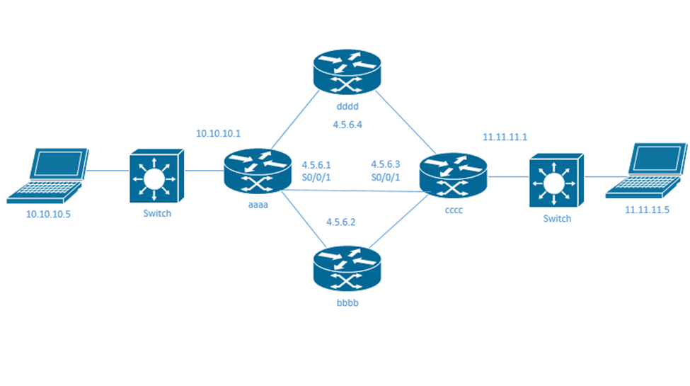
For example, I would like to program router aaaa to use a static route to router cccc’s network (11.11.11.0/24). I know that router cccc is connected to router aaaa via the interface S0/0/1.
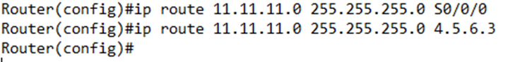
- I would write ip route 11.11.11.0 255.255.255.0 S0/0/0. In effect, I told my router “send packets addressed to the 11.11.11.0/24 network out via the S0/0/0 interface, and the device on the other end of that interface will take care of the rest”.
- I could also write ip route 11.11.11.0 255.255.255.0 4.5.6.3 because I know that router cccc has an IP address of 4.5.6.3. In effect, I told my router “send packets addressed to the 11.11.11.0/24 network to 4.5.6.3, and 4.5.6.3 will take care of the rest”.
If we create a route using a destination IP, the router will only use it if the destination has a route already. That means that router aaaa will only use this route if it knows of an actual route to 4.5.6.3 first. In our case, 4.5.6.3 is directly connected to interface S0/0/1. But if it wasn’t – if our router couldn’t reach 4.5.6.3, or if S0/0/1 wasn’t configured – this command would not accomplish anything. Remember, when we enter this command, the router must guess which interface 4.5.6.3 is connected to.
Notice that I wrote out the full subnet mask in the command.
The router removes static routes from its routing table when they stop working. When they start working again, they are added back. If we want to keep the route in the table no matter what, we type ip route <subnet name> <subnet mask> <local interface> permanent.
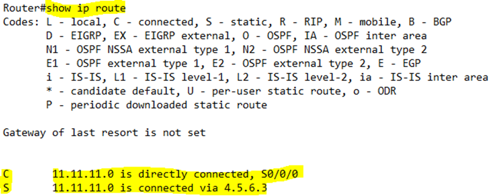
We can verify the static routes configured inside our router by typing show ip route static. The first route (the one with the S0/0/0 interface will show up in the routing table as being “directly connected”. The second route (the one with the 4.5.6.3 IP address) will show up in the routing table as being connected “via 4.5.6.3”.
A static route is assigned a priority (administrative distance) of 1. It is always the first route used, when there are multiple routes with the same prefix length. If we want to give a static route a shorter priority, we type ip route <subnet name> <subnet mask> <local interface> <priority>, for example ip route 11.11.11.0 255.255.255.0 4.5.6.3 priority 90.
How can we troubleshoot a static route? What could go wrong?
- The router does not check to make sure that the static route is accurate when we enter it. The router cannot predict the external network topology. If we have the wrong subnet or the wrong network name or the wrong destination or the wrong interface, then the route won’t work.
- If the route is configured correctly but does not appear routing table, that means we didn’t add the route, or the link is down, or the router doesn’t have a connected route for our static route.
- Even if the route is in the routing table, the router might not use it if another route with a shorter administrative distance or longer prefix is present.
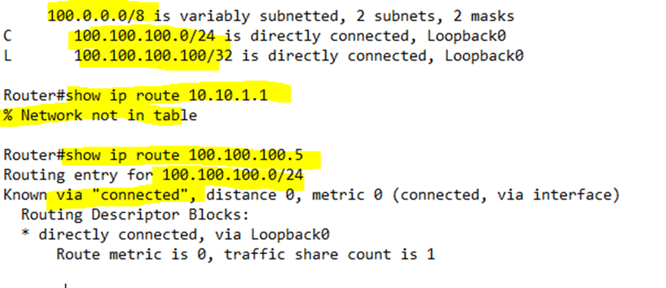
If we type show ip route <IP address> the router will tell us what route it will choose to get to a particular IP address. For example, I have only three active routes in my router. I asked the router what route it would choose to reach 10.10.1.1, but it didn’t have an active route. I asked the router what route it would choose to reach 100.100.100.5, and it said that it was directly connected. It matched the route with the network 100.100.100.0/24.
We can configure an IPv6 static route by typing ipv6 route <destination network> <next-hop IPv6 address> or ipv6 route <destination network> <outgoing interface>. We can specify both the next-hop IPv6 address and the outgoing interface.
We can configure the global unicast address or the link-local address of the next router as our destination.
If we use a global unicast address, the router can determine the proper outgoing interface to get to the destination. If we use a link-local destination address, we must also specify the outgoing interface through ipv6 route <destination network> <outgoing interface> <next-hop IPv6 address>.
We can create a route to a single IP address instead of a network. It is just a matter of using a /128 mask. We would type ipv6 route <destination network/128> <next-hop IPv6 address>.
For example
- My destination router has a network of aaaa:aaaa:aaaa:aaaa:: /64,
- My destination router has an IPv6 address of aaaa:aaaa:aaaa:aaaa:bbbb:bbbb:bbbb:bbbb facing my local router’s interface,
- My destination router has an IPv6 link-local address of fe80:0000:0000:0000:0000:0000:0000:0000 facing my local router’s interface, and
- My destination router is connected to my local router’s G0/0/1 interface
I could configure a static route with any of the following commands
- ipv6 route aaaa:aaaa:aaaa:aaaa:: /64 aaaa:aaaa:aaaa:aaaa:bbbb:bbbb:bbbb:bbbb – this tells the router to send traffic to the aaaa:aaaa:aaaa:aaaa:bbbb:bbbb:bbbb:bbbb router. Since this is a global unicast IPv6 address, our local router automatically detects it on the G0/0/1 interface and knows to send traffic out of that interface.
- ipv6 route aaaa:aaaa:aaaa:aaaa:: /64 G0/0/1 – this tells the router to send the traffic out of the G0/0/1 interface. The router already knows the IPv6 address of the destination router connected to this interface.
- ipv6 route aaaa:aaaa:aaaa:aaaa:: /64 G0/0/1 fe80:0000:0000:0000:0000:0000:0000:0000 – this tells the router to send traffic out the G0/0/1 interface, but also that it should go to the fe80:: address.
Remember that like in IPv4, a router will automatically detect directly connected IPv6 addresses and create routes for them. It won’t create routes for directly connected link-local addresses.
To configure the default route, we type ipv6 route ::/0 <outgoing interface>. We could also type ipv6 route ::/0 <destination>. Remember that since this route has the widest prefix, the router will choose it last.
When we want the router to give priority to routes learned from a routing protocol, but also want it to remember some static routes in case those protocols fail, we configure a floating route. A static route has an administrative distance of one. That is the highest priority a route can have. We can give a static route a higher administrative distance by typing ip route <destination network> <next-hop IP address> <administrative distance> or ipv6 route <destination network> <next-hop IPv6 address> <administrative distance>.
We should give the route an administrative distance that is higher than the one given to the routing protocol in use.
We can verify the routes by typing
- show ipv6 route local to see the local routes
- show ipv6 route static to see the static routes
If we want to know which route a router will take, we can ask it with show ipv6 route <IPv6 address of destination> and the router will tell us what route it would choose.
We should always verify the static route before entering it. Verify that you chose the correct interface, next-hop IPv4 or IPv6 address, and prefix/prefix length or subnet mask. The Cisco router will accept static route commands that are poorly constructed, as long as the syntax is correct.
Routers and VLANs didn’t make sense earlier because we didn’t know enough about routers. But remember that if I want to pass traffic between two VLANs, I need either a router or a Layer 3 switch.
Let’s say that I have a switch with four VLANs
- Ports 1 through 12 are on VLAN 1
- Ports 13 through 24 are on VLAN 2
- Ports 25 through 36 are on VLAN 3
- Ports 37 through 48 are on VLAN 4
If I want to route traffic between devices on the different VLANs, I might connect a router to Port 1, Port 13, Port 25, and Port 37. That is, I connect one router interface to a port on each VLAN. This is inefficient; it wastes ports. If I have many VLANs, it may not even be possible.
We can instead make one port on the switch an 802.1Q trunk port and connect the router to it. Packets that need to move between VLANs travel through the trunk port and up into the router. The router moves the packet to the correct VLAN and sends it back down to the trunk port. The switch now has a packet in a different VLAN. This is known as a Router on a Stick configuration or ROAS because in a network diagram, it appears like a router is connected via a single cable (a stick).
How do we configure a router on a stick? Or how do we configure a router to connect to a trunk port on a switch using a single physical interface? We must set up a sub interface for each VLAN on the router.
We can enter the sub interface configuration for any router by typing interface <name>.<subint>. If the sub interface doesn’t exist, the router will create it automatically. For example, to configure the subinterface two on interface G0/0/1, I typed
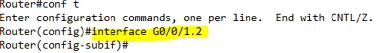
Notice that the router entered the “subif” or sub interface configuration.
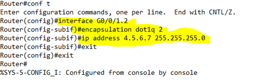
We configure the VLAN on the sub interface with the following commands
- encapsulation dot1q <VLAN ID> – tells the router that we are using encapsulation on this sub interface and what the VLAN ID is.
- ip address <IP address> <subnet mask> – assigns an IP address to the VLAN sub interface
In this example, I configured interface G0/0/1.2 to use VLAN 2, and I set the IP address 4.5.6.7/24 on it.
On the switch side, we add the switchport mode trunk command to the physical interface. We don’t set an IP address or VLAN on a switch trunk port.
Technically, the sub interface number doesn’t need to match the VLAN number. We could have created sub interface 5 and added VLAN 2 to it. We only need to ensure that we assign the sub interface an IP address/subnet that are in the VLAN.
If we configure an IP address on the physical interface, it is assumed to be in the native VLAN. We can set the native VLAN on a sub interface by typing encapsulation dot1q <VLAN ID> native.
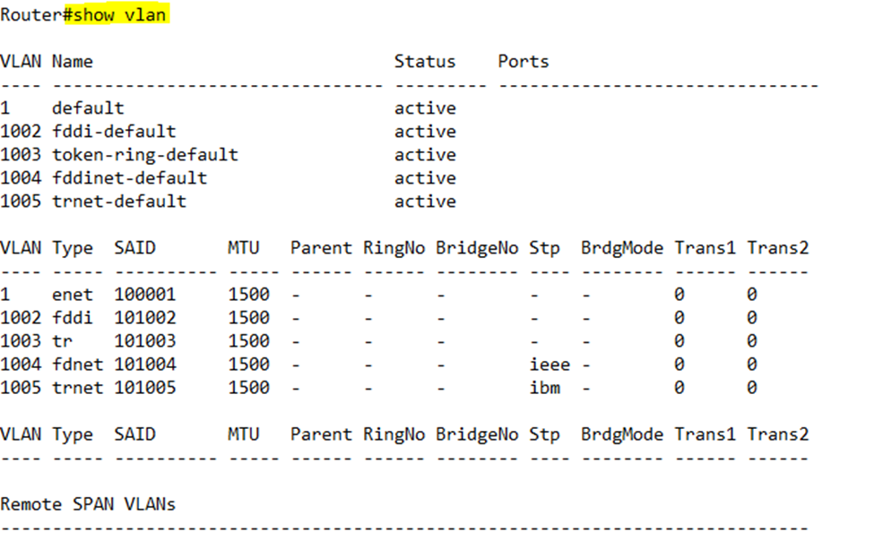
We can see the active VLANs by typing show vlan
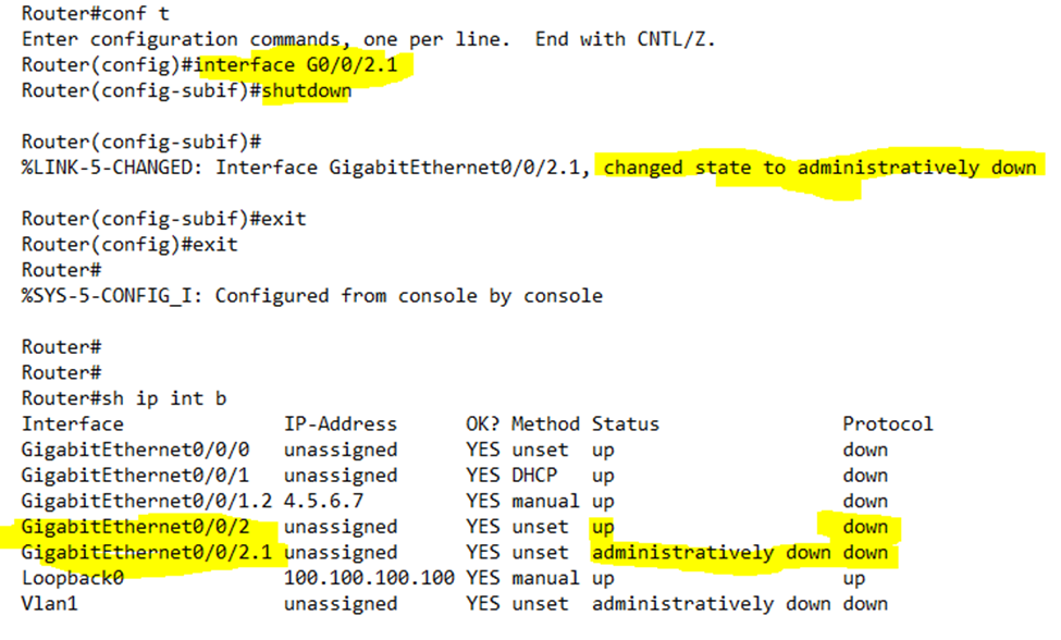
When we perform a shutdown on a physical interface, the router shuts down all the associated sub interfaces. For example, if we shut down G0/0/2, the router shut down G0/0/2.1 as well.
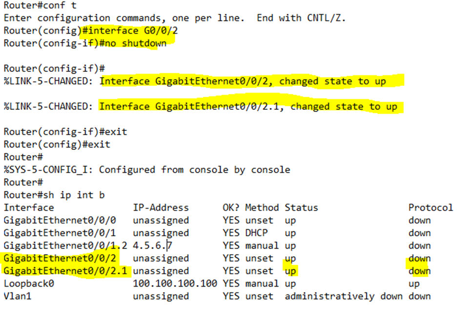
When we perform a no shutdown on a physical interface, the router starts up all the associated sub interfaces. For example, if we perform a no shutdown on G0/0/2, the router starts up G0/0/2.1 as well.
If the main interface is shut down, we cannot start up one of its sub interfaces. But if the main interface is up, we can start up and shut down any of its sub interfaces. I shut down G0/0/2.1, but kept G0/0/2 up.
Some ROAS troubleshooting tips
- Make sure that your VLANs are configured correctly on your LAN switches
- Make sure that you have identified every VLAN configured on each LAN switch, and created a sub interface on the router for each VLAN
- Make sure that you have created the sub interfaces under the correct router physical interface
- Check that each sub interface is configured with the correct IP address and subnet
- Check that the native VLAN has been configured on the router and on the switch
- Make sure that none of the interfaces or sub interfaces are shutdown
If we’re using a layer three switch to route traffic, we must first enable routing on the switch
- Enable routing with the sdm prefer lanbase-routing command. We must then reload the switch for this command to activate.
- Once the switch is back up, turn on IP routing with the ip routing command
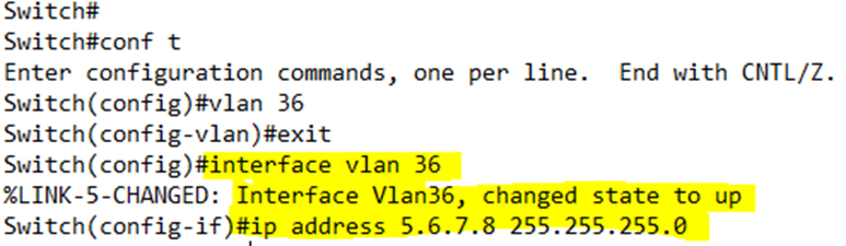
- Configure each VLAN interface on the switch. When we configure a VLAN on a switch, we type vlan <VLAN ID>. When we configure a VLAN interface, we type interface vlan <VLAN ID>. This is known as a Switched Virtual Interface, or SVI.
- Assign the VLAN interface an IP address through the ip address <IP address> <subnet mask> command
I created VLAN 36. When I accessed it through the interface vlan 36 command, the switch changed it state to up.
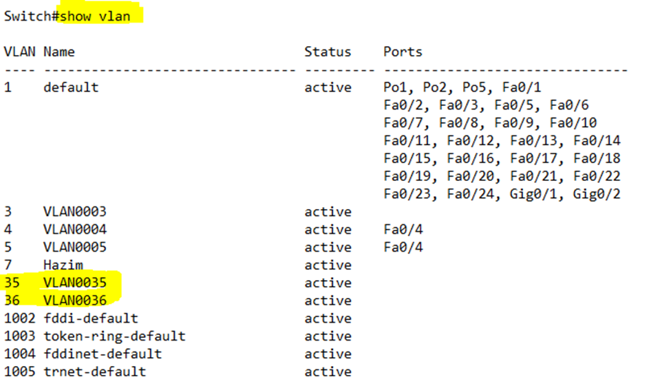
When we create the VLAN interface, it automatically creates the VLAN as well. We can verify the VLAN by typing show vlan.
We can also verify the VLAN interface by typing show interface VLAN36 or show interface to show all the interfaces.
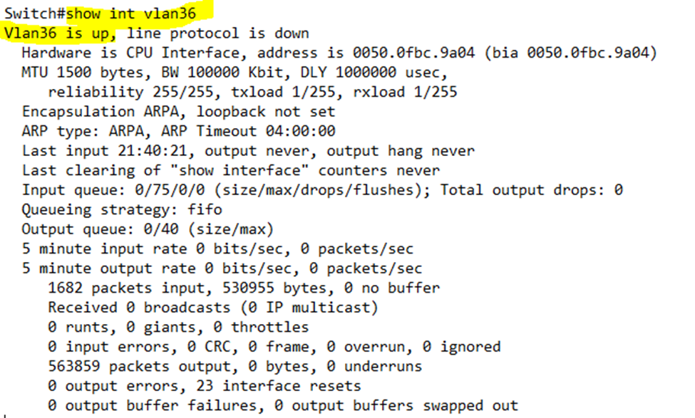
On a layer three switch, the VLAN interface state is the same as the actual VLAN state. For the VLAN to be up
- The VLAN must be defined on the switch – either explicitly or learned through VTP
- At least one access interface on the switch is assigned to the VLAN and is up, or a trunk interface on that switch has the VLAN assigned to it
- The VLAN is not shutdown
- The VLAN interface is not shutdown
You can think of a Layer 3 switch as a switch with a built-in router. The VLAN interfaces belong to the router part. Since they operate separately, they must both be up for routing to work.
The physical interface ports on the switch belong to the switch. But we can make a physical interface act like a router interface. We call this a routed port.
Any frame that arrives on the routed port is handled like a packet instead
- The switch (the router part of the switch) strips the ethernet header/trailer from the frame, exposing the destination IP address
- It checks the routing table on the switch and determines where the packet goes. Remember that we configured an IP address for each VLAN interface.
- It encapsulates the packet in a new ethernet frame and send it back to the switch part of the switch. The switch sends the packet to its destination.
We only use the routed port when we have a single port connected to a subnet. When we have multiple ports, we should use the SVI configuration
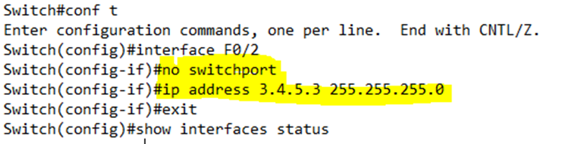
In the interface configuration, we type no switchport to create the routed port. If we want to go back to a switchport, we just type switchport.
Enter the interface configuration
- Type no switchport
- Assign the port an IP address through the ip address <IP address> <subnet> command
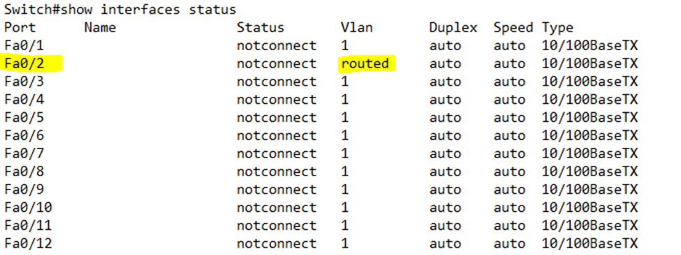
We can verify the settings by typing
- show interfaces – gives us many details about each interface, including the VLAN interfaces
- show interfaces status – provides a summary about each interface in a table. The routed ports say “routed” under the VLAN; only physical ports are shown through this command
In a tiered design, the ports on the core switches are usually routed ports. This is an important configuration because core switches are connected to multiple VLANs
What happens when we want to use a Layer 3 protocol over redundant links through EtherChannel? EtherChannel over Layer 3 allows a switch can balance the Layer 3 traffic over multiple links.
To configure the EtherChannel on Layer 3
- We must first configure the PortChannel interface (this is the separate virtual interface)
- interface port-channel <number>
- no switchport
- ip address <IP address> <subnet mask>
- interface port-channel <number>
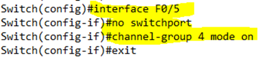
- Configure each interface to be part of an EtherChannel as before
- no switchport – configures the port as a routing port
- no ip address – this is added to the interface automatically when we add the no switchport
- channel-group <number> mode on – adds the port to the PortChannel
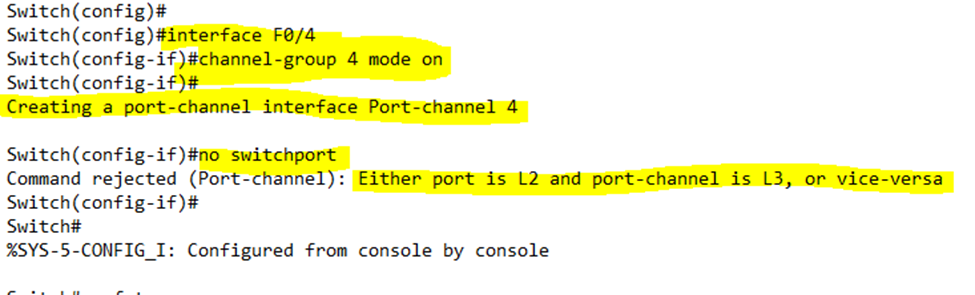
It is important to follow the above commands in order. I tried to add Channel-Group 4 on to interface F0/4 before creating Channel-Group 4. The result is that the switch automatically created the Port-Channel 4 virtual interface. When I ran the no switchport command it failed.
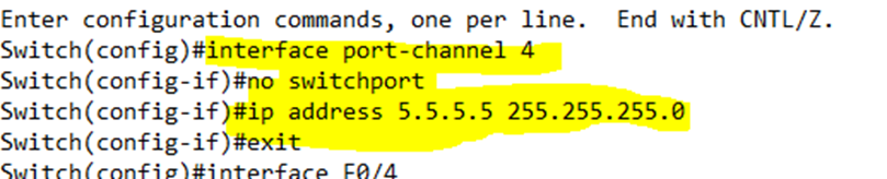
I went back and configured the Port-Channel 4 virtual interface as a routed port and added an IP address to it.
Then I added the no switchport and port-channel commands to the interfaces.
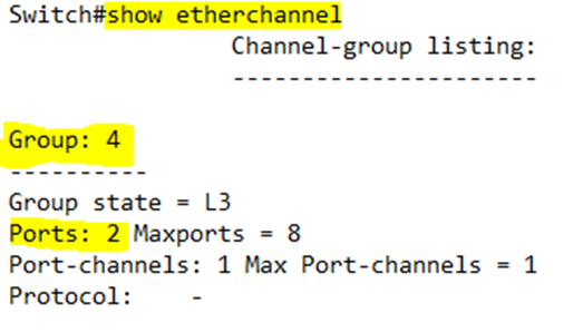
We can verify these settings by typing show etherchannel. The switch will provide us with a list of active etherchannels and the number ports in each one.
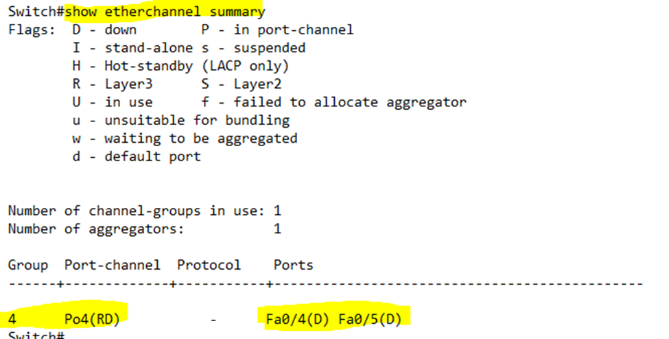
If we type show etherchannel summary, we can see additional details such as the ports added to each etherchannel.
For EtherChannel to work, remember that the speed and duplex must be the same on all ports and that routing must be enabled on each port.