
3.4 Configure and verify single area OSPFv2
3.4.a Neighbor adjacencies
3.4.b Point-to-point
3.4.c Broadcast (DR/BDR selection)
3.4.d Router ID
We will now look at dynamic routes. The internet is massive and there are millions of routers on it. There is usually more than one way to get to a destination. Routers and links fail all the time. How can a router determine the best route in real time as it changes?
We use a routing protocol. A routing protocol is a set of rules for learning and updating routes. The main routing protocol that we will look at is OSPFv2
A routed or routable protocol is one that allows a router to forward packets. IPv4 and IPv6 are routable protocols. IPv4 allows a router to send packets, but it does not help the router figure out where to send the packets.
The idea behind the routing protocol
- A router can learn routing information from its neighbors (routers that are directly connected to it)
- It can teach a neighbor about routes that it knows and that it has learned from other neighbors
- It can pick the best route to a destination when more than one route is available
- It can detect failed routes and select new best routes. This is called convergence.
When a router receives a packet, the only decision it makes is which router to send it to next. It doesn’t need to plan out the packet’s entire route. Each router decides on the packet’s next destination. But collectively, the routers use routing protocols to figure out the best route.
There are two types of routing protocols. To understand how they work, we need to understand what an autonomous system or AS is. It is a network that is under the control of one organization. For example, the network at your office is a single AS. The internet is not an AS because there are thousands of ISPs, each with control of their own network. These networks work together, but each one is controlled by a different party.
- Interior Gateway Protocols, or IGPs. An IGP works inside a single autonomous system or AS. An IGP allows packets to be routed inside the system.
- Exterior Gateway Protocols, or EGPs. An EGP works between multiple autonomous systems. An EGP allows packets to be routed between different systems. The only EGP that we will learn about is Border Gateway Protocol, or BGP.
Each AS is assigned a unique number, called an AS Number (ASN). It is kind of like an IP address and is unique for that AS worldwide.
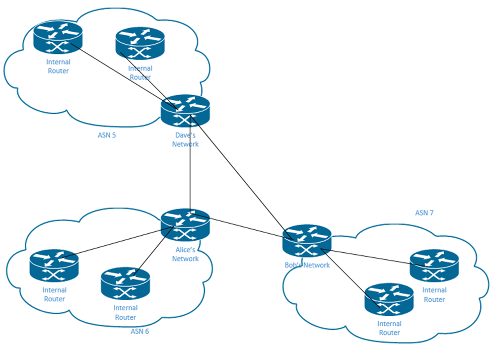
In the diagram below, we have three ASNs – ASN 5 belonging to Dave, ASN 6 belonging to Alice, and ASN 7, belonging to Bob. Each ASN has its own internal network, which could consist of multiple routers. Each router may maintain its own local network (LAN). Thus each ASN could consist of multiple LANs.
Notice that there is a router at the edge of each ASN. This edge router gives the ASN connectivity to other ASNs.
.
There are many different EGPs available and you can choose the one that is right for you. The two most popular ones are OSPFv2 and EIGRP (Enhanced Interior Gateway Routing Protocol), but the CCNA only focuses on OSPFv2.
Inside the routing protocol is an algorithm (a kind of artificial intelligence or set of rules) that figures out how to learn the routes and choose the best one. There are three categories of algorithms
- Distance Vector – The distance vector calculates the distance that a packet must travel from its source to its destination. The distance vector usually calculates the number of routers or “hops” that the packet must pass through. These algorithms are not popular because they are slow to update when the network topology changes.
- Link State – this type of algorithm calculates the distance to the packet’s destination based on the cost (or speed) of each link.
- Advanced Distance Vector – This type of algorithm uses both the distance vector and the link state algorithms. EIGRP is an example of an advanced distance vector.
How does each routing protocol work?
- RIPv2 – How many hops (routers) does a packet have to travel through? RIPv2 is considered a Distance Vector algorithm. RIPv2 selects the route with the lowest cost. It has slow convergence (it takes a long time to update when the network topology changes.
- OSPF – How much does each route cost? We assign a cost to each link based on its bandwidth and add them up. OSPF selects the route with the lowest cost. OSPF is considered a link state algorithm.
- EIGRP – EIGRP factors in the cost of each link, the amount of delay in each interface and the number of links. It’s considered an advanced distance vector algorithm.
RIP might choose a route with a single hop even though the connection is slower, whereas OSPF might choose a route with multiple routers (and potentially high latency) even though the connection speed is faster.
What if we have multiple routing algorithms in use? What if we connect a network using OSPF with one using EIGRP? We can take routes learned from one protocol and advertise them through another protocol. This is called route redistribution.
What happens when the router learns about the same destination (route) through multiple algorithms? We assign each algorithm an administrative distance. The distance is how much weight we should give to each algorithm. The lower the weight, the more likely we are to use it.
The table below (repeated from earlier) summarizes the distance associated with each route source.
| Route Source | Default Distance Values |
| Connected interface | 0 |
| Static route | 1 |
| Enhanced Interior Gateway Routing Protocol (EIGRP) summary route | 5 |
| External Border Gateway Protocol (BGP) | 20 |
| Internal EIGRP | 90 |
| IGRP | 100 |
| OSPF | 110 |
| Intermediate System-to-Intermediate System (IS-IS) | 115 |
| Routing Information Protocol (RIP) | 120 |
| Exterior Gateway Protocol (EGP) | 140 |
| On Demand Routing (ODR) | 160 |
| External EIGRP | 170 |
| Internal BGP | 200 |
| Unknown | 255 |
Clearly, a connected or static route has the highest priority, followed by BGP (external route) and then an internal route. We can change the administrative distance, but we must do so on each router.
We can give an individual static route a larger administrative distance by typing ip route <network ID> <subnet mask> <destination> <distance>.
Now let’s look at how OSPF works. Each router is busy gathering information about its routes like the static and directly connected routes.
The router maintains a database called the Link State Database or LSDB, which contains its idea of how the internet is organized and connected. Each time the router learns a new route, it sends out a message called the Link State Advertisement (LSA) telling the neighboring routers what it learned. The other routers put the data from the LSA into their databases. The neighboring routers flood the LSA to other routers. But a router will only accept and reflood an LSA if it doesn’t already have it. This prevents the LSA from flooding in an endless loop. By default, the LSA expires after 30 minutes.
After a while, all the routers that are connected (directly or indirectly) have the same LSDB – they learned about the network topology from other routers and updated it accordingly, but they still don’t know about the best pathway to each network. What is the relationship between the LSDB and the routing table?
Well, the router analyses the LSDB and creates routes by calculating the best ones. We will see how.
Two routers are considered OSPF neighbors if
- They are directly connected. They can be directly connected over an ethernet WAN, a serial link, or a switch. They must be on the same VLAN.
- They use OSPF
- The two routers exchange OSPF messages
- They agree to become neighbors because of the OSPF messages
A router can have multiple OSPF neighbors. We can see a router’s neighbors by typing show ip ospf neighbor.
A new router can connect to the network and send OSPF Hello messages. Other routers with OSPF will be listening for the message and create a neighbor relationship. The Hello contains the router’s unique router ID (a 32-bit number that is by default the router’s IPv4 interface address). We can configure a different RID if we want.
A router sends the Hello message in a packet to 224.0.0.5 which is a multicast IP address that all the OSPF routers listen on. In summary
- We connect two routers to each other
- They don’t know anything about each other
- One router sends the Hello to 224.0.0.5. The Hello contains the RID
- The other router replies acknowledging the Hello, and sends its own RID in reply
- Each router verifies that the Hello messages are sent without error
When two routers agree to become neighbors, they do not automatically exchange the entire contents of their LDSB. Instead each router tells the other router which LSAs it has in its database. Each router then determines which LSAs are missing and requests them from the other routers.
Each router continues to send the other router Hello messages at regular intervals so that the other router can verify that it is still operational.
Each router maintains two timers
- The Hello Interval is how often a hello message is sent
- The Dead Interval is how long a router will wait without receiving a hello message. By default, it is four times the hello interval. Once the hello messages stop coming in, the router assumes that the neighbor has died.
When we have multiple routers on the same VLAN, one is elected to be the Designated Router (DR) and a second one is elected to be a Back-Up Designated Router (BRD). The DR is responsible for providing other routers with a copy of the LSDB. If the DR fails, the BDR takes over, and a new router is selected to be the BDR.
It is better to have a DR and a BDR when there are multiple routers. Otherwise, each router will attempt to share its LSDB with all the other routers.
The IP address 224.0.0.5 is a multicast address that the DR can use to send messages.
The IP address 224.0.0.6 is a multicast address that a router can use to send a message to the DR
The routers that aren’t a DR or BDR are called DROthers. They do not establish a full OSPF state.
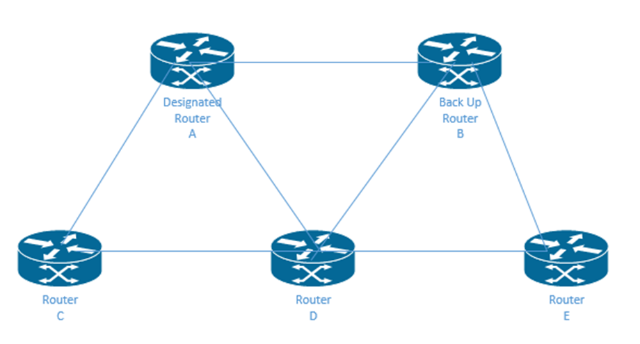
I have five routers – A, B, C, D, and E. Router A is the designated router and Router B is the Back-Up Designated Router.
On a DROther router, if we type show ip ospf neighbor, we see
- Fully adjacent neighbors for the DR and BDR. Two routers that are on the full state are adjacent neighbors, also known as fully adjacent neighbors. That is, they have exchanged the link state database.
Routers A and B are fully adjacent with each other and with routers C, D, and E. That is, we have the following fully adjacent neighbor relationships: A-B, A-C, A-D, A-E, B-C, B-D, and B-E. - 2-way state neighbors for the other DROthers. Two routers are neighbors if they have the 2-way state and are on the same link.
We have the following 2-way state neighbor relationships: C-D, C-E, and D-E.
But how does OSPF rank each route? Under OSPF, the metric is – what is the sum of the cost of each outgoing interface in the route? Whichever route is the cheapest is best. OSPF only looks at the outgoing interfaces.
That means that the router on the other end of the route may choose a different way back.
In the following example, Bob’s Network and Dave’s Network want to communicate. There are 5 routers in between – A, B, C, D, and E. What are all the routes from Bob’s Network to Dave’s Network? The cost of each outgoing interface is in brackets.
- Bob’s Network (3) – Router A (6) – Router B (4) – Dave’s Network. The total cost is 13.
- Bob’s Network (3) – Router B (4) – Dave’s Network. The total cost is 7. This is the best route.
- Bob’s Network (3) – Router C (5) – Router D (6) – Dave’s Network. The total cost is 14.
- Bob’s Network (3) – Router C (5) – Router D (6) – Router B (4) – Dave’s Network. The total cost is 18.
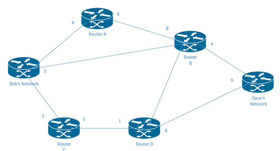
On the way back
- Dave’s Network (6) – Router B (8) – Router A (4) – Bob’s Network. The total cost is 18.
- Dave’s Network (6) – Router B (8) – Bob’s Network. The total cost is 14.
- Dave’s Network (6) – Router B (8) – Router D (1) – Router C (2) – Bob’s Network. The total cost is 17.
- Dave’s Network (6) – Router D (2) – Router C (3) – Bob’s Network. The total cost is 11. This is the best route.
What happens when we have many routers and subnets? The routers must keep track of thousands of other routers in the memory. The LSDB will be massive and the computing power to search it will be massive. If a single router stops working, all the other routers must recalculate the entire algorithm and routes.
To solve this, we break down the system into OSPF areas. We can group our routers into different areas. When we use multiple areas, a router must think about the route in its own area and no others. When we have more than 50 routers, we should use areas.
How do we decide which routers belong to which areas?
- The interfaces in the same subnet should be the same area
- Each area should be contiguous
- There will be several types of routers
- We might choose a large router to be the Backbone Router. The Backbone router connects to all the areas and controls the backbone area.
- A router can be considered “internal” if all its interfaces connect to routers that are in the same area
- An Area Border Router (ABR) has some interfaces in the backbone area and some in the non-backbone area
- A non-backbone area must be able to reach the backbone area by having an ABR that connects to both the backbone area and the non-backbone area
- Any router that connects to the backbone area is a backbone router – an ABR can also be a backbone router
- An intraarea route is one that goes between routers in the same area
- An interarea route is one that goes between routers in different subnets
In my diagram, I have two areas. At the top is my backbone router, which resides in the backbone area. Below are two Area Border Routers. Each ABR connects to the Backbone Router. We also have Internal Routers A, B, F, and G.
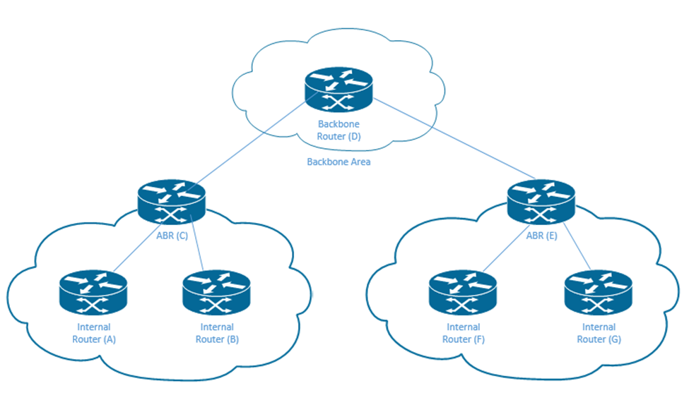
The internal routers on the left (A and B) don’t need to know the route all the way to internal routers F and G. But a router must still know that there are other subnets in other areas so that it can send them traffic. It only needs limited information – the subnet. It doesn’t need to know how routers in other area are connected.
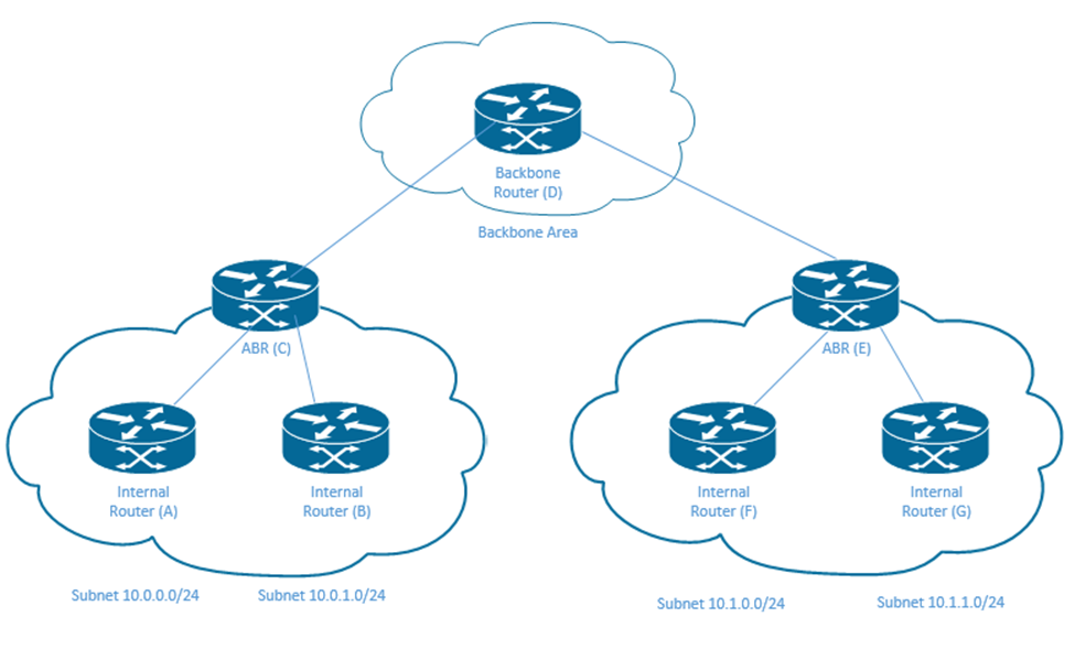
On the left, we have subnets 10.0.0.0/24 and 10.0.1.0/24. Router A and Router B need to know the exact routes to those subnets. On the right, we have subnets 10.1.0.0/24 and 10.1.1.0/24. Router A and Router B do not need to know the exact routes. Instead they just say that those networks are connected router C, the Area Border Router. Router C can figure out how those packets get to the ABR E, and ABR E can figure out how packets addressed to those networks can get to Routers F and G.
What does the LSDB look like?
- There is one router LSA for each router in our area. This is called a Type 1 LSA. It contains the following information
- Router ID
- Router Interfaces
- IP address/netmask
- Router Interface Status
- What neighbors the other router knows
- There is one network LSA for each network that contains a DR if the DR has at least one neighbor that is connected to our router. This is called a Type 2 LSA. A Type 2 LSA always stays within the area that created it. It contains the following information
- DR address
- BDR address
- Subnet ID and mask
- There is one summary LSA for each subnet in a different area. This is called a Type 3 LSA. It contains the following information.
- Subnet ID and Mask
- RID of the ABR that advertised the LSA
Now for the fun part. How do we configure OSPF?
- Type route ospf <process ID> to enter the OSPF configuration mode. The process ID allows us to have multiple OSPF processes on a single router. The process ID is between 1 and 65535 and can be different on every router.
- Configure the OSPF router ID. OSPF will use the router ID. If a router ID is not configured, OSPF will use the IP address of the loopback interface or of a physical interface.
- Type router-id <ID> to give the router an ID number. The ID must be in the format of an IP address.
- Create a loopback interface by typing interface loopback <number>. This will automatically create a loopback interface and enter its configuration.
Add an IP address to the interface by typing ip address <IP address> <subnet mask>.
If there are multiple loopback interfaces, the router will choose the largest IP address as the OSPF Router ID.
- Assign an IP address to a physical interface. The router will choose the highest IP from the interfaces that are up.
- Configure the OSPF router ID. OSPF will use the router ID. If a router ID is not configured, OSPF will use the IP address of the loopback interface or of a physical interface.
If we change the router ID while the router is running, it won’t take effect until the router is rebooted.
- Type network <IP address> <wildcard mask> area <OSPF Area ID> to enable the OSPF on any interface that matches the IP address and wildcard mask. There are five wildcards
- Wildcard 0.0.0.0 – the IP address must match exactly
- Wildcard 0.0.0.255 – first three octets must match
- Wildcard 0.0.255.255 – the first two octets must match
- Wildcard 0.255.255.255 – the first octet must match
- Wildcard 255.255.255.255 – this wildcard matches everything
For example
- IP address 5.5.5.5 and wildcard 0.0.0.0 will only match IP address 5.5.5.5
- IP address 5.5.5.5 and wildcard 0.0.0.255 will match any IP address that starts with 5.5.5, which is the range of IP addresses 5.5.5.0 to 5.5.5.255
- IP address 5.5.5.5 and wildcard 0.0.255.255 will match any IP address that starts with 5.5, which is the range of IP addresses 5.5.0.0 to 5.5.255.255
- IP address 5.5.5.5 and wildcard 0.255.255.255 will match any IP address that starts with 5, which is the range of IP addresses 5.0.0.0 to 5.255.255.255
- IP address 5.5.5.5 and wildcard 255.255.255.255 will match any IP address
If you enter a network IP address and doesn’t match the wildcard, then it will be changed. The octet in the IP address will be set to 0 when the octet in the wildcard is 255. For example, if I write 252.342.432.4 wildcard 0.0.0.255, the router will change my IP address to 255.342.432.0
Notice that we didn’t configure OSPF on a physical interface. We just configured a network IP address with an area ID. The router automatically interprets the OSPF configuration and applies it to any applicable interface.
Router OSPF is a process, not just a configuration. Therefore, OSPF will not start unless there is at least one working physical interface.

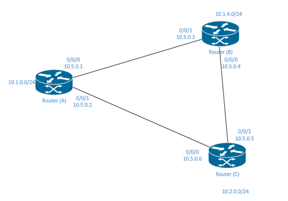
In my example, I have three routers in my OSPF area (area 1).
- Router A controls subnet 10.1.0.0/24
- Interface 0/0/0 connects to Router B
- Interface 0/0/1 connects to Router C
- Router B controls subnet 10.1.4.0/24
- Interface 0/0/0 connects to Router C
- Interface 0/0/1 connects to Router B
- Router C controls subnet 10.2.0.0/24
- Interface 0/0/0 connects to Router A
- Interface 0/0/1 connects to Router B
If I enable OSPF on Router A with the network 10.0.0.0 0.255.255.255 area 1, it will match the networks that are controlled by Router B and Router C. Therefore, the router will enable OSPF on both interfaces 0/0/0 and 0/0/1.
If I enable OSPF on Router A with the network 10.2.0.0 0.0.255.255 area 1, it will match the network that is controlled by Router C. Therefore, the router will enable OSPF on interface 0/0/1.
We can verify OSPF with the following
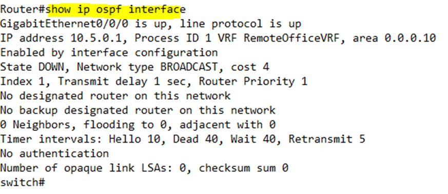
show ip ospf interface to see if the interfaces are enabled with OSPF. Only an OSPF enabled interface is listed
- show ip ospf interface brief to see one line per interface
- show ip ospf interface <interface name> to see details about just one interface
show ip ospf neighbor to see the neighbor relationships

The output from the show ip ospf neighbor command tells us the following
- Neighbor ID – the neighbor’s IP address or ID
- Priority – the priority of the neighboring router
- State – the state tells us the status of the neighboring router. We want the state to be FULL. The state also tells us if the router is a DR, BDR, or DROTHER.
- FULL/ – the state is full
- FULL/DR – the state is full, and the neighboring router is a Designated Router
- FULL/BDR – the state is full, and the neighboring router is a Back Up Designated Router
- FULL/DROTHER – the state is full, and the neighboring router is a DROTHER (neither a designated router nor a back up designated router). That means that our router is probably a DR or a BDR.
- 2WAY/DROTHER – the state is two-way. That means that both routers are DROTHER, which is why they didn’t reach a full state.
- Address – the address of the neighboring router’s interface
- Interface – the local interface of the router that is connected to the neighbor
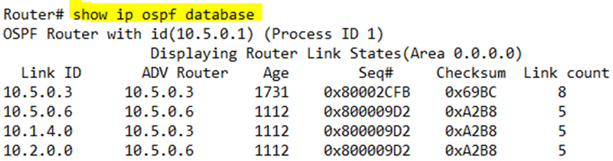
show ip ospf database to see the LSAs received from our neighbors. Our router has learned routes from the other two routers. The ADV Router is the IP address of the router that is advertising the LSA. The Link ID is the ID (IP address) of the router that we learned the LSA from.
If we learn the LSA from a router that advertised it, then both the Link ID and ADV Router will be the same. If the router we learned the LSA from received it from another router, then they would be different.
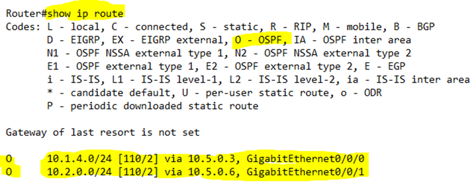
show ip route to see the routes that the router figured out from the database. We can see that our router learned two routes – a route to 10.1.4.0/24 via G0/0/0 and a route to 10.2.0.0/24 via G0/0/1.
If we run the show ip ospf database command on multiple connected routers, we should see the same data. Why? All connected routers share the same LSDB data. If there is a mismatch, it could indicate that the OSPF Hello messages
If OSPF is our only routing protocol, and if we know how many subnets there are in our area and how many are directly connected, we can subtract them to determine how many we should learn via OSPF
I can enable the OSPF on a per-interface basis
- Enter OSPF configuration. Type no network <network ID> area <area ID> to remove OSPF networks from the OSPF configuration
- Enter the interface configuration mode for each interface we want to enable OSPF on. Type ip ospf <process ID> area <area ID> to enable OSPF
If we type show ip ospf interface, it will show up as “attached via interface” instead of “attached via network”.
A passive interface is one that does not have a router connected to it. The router will not send Hello messages or accept Hello messages on this interface. It will still advertise the subnet connected to this interface via OSPF.
We can make an active interface into a passive interface. This is a good idea when we are using a router to connect multiple VLANs on the same physical LAN.
- The passive-interface <interface name> in the main configuration changes that interface to passive
- The passive-interface default makes all interfaces passive
- The no passive-interface <interface name> in the main configuration returns that interface to passive
We can verify the interface status by typing show ip ospf interface brief.
When we have a large network, and in that network, we have a single default route to the internet, the router with the connection to the internet should teach all the other routers about it. Remember that the default route is the route that a router uses when no other routes match the destination of the packet. By default, a router won’t advertise its default route. In the OSPF configuration, we type default-information originate to tell the router to advertise its default route over OSPF (in the OSPF configuration). The router will advertise this route whether it is working or not. Now internal routers will know to pass their traffic to the internet-connected router when they have traffic that needs to reach the internet.
At the beginning of this chapter, I said that OSPF chooses the cheapest route, and that it bases the cost on the outbound interface. But how does it know how much an interface costs?
The cost of an interface is based on its speed. By default, a router has a reference speed of 100,000. What the router does is divide the interface speed by the reference speed to obtain the cost.
For example, a Fast Ethernet interface has a speed of 100,000. The cost is 100,000 / 100,000 = 1. A 10 mbps interface has a speed of 10,000. The cost is 100,000 / 10,000 = 10.
A Gigabit Ethernet interface speed is 1,000,000. The cost is 100,000 / 1,000,000 = 0.1. But the router won’t accept a speed that is less than 1. As a result, all interface speeds that are 100 mbps or greater have a cost of 1.
A better system would be to set the reference to a higher value, but OSPF was developed before higher speeds existed, and the reference has not been updated.
We can change the cost or the interface or the reference value
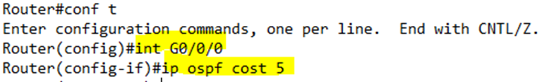
- On a specific physical interface, we can manually set the cost by typing ip ospf cost <cost>. This only changes the cost on a single interface.
- We can change the interface’s bandwidth by typing bandwidth <speed>, where speed is in Kbps. Remember that the router calculates the cost from the interface’s bandwidth setting. It is generally a bad idea to change the bandwidth.
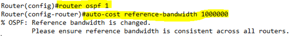
- Change the reference bandwidth by typing auto-cost reference-bandwidth <speed> in Mbps. On some routers, the speed is in Gbps. This command is entered in the OSPF configuration mode. This affects calculations for all interfaces.
When the router has multiple routes to the same destination network with the same OSPF cost, it chooses the one with the lowest Router ID. We might want the router to maintain multiple routes for redundancy. We can permit a router to maintain multiple paths by typing maximum-paths <maximum number of routes>. Now the router will maintain multiple routes and balance the traffic on all of them. The router will balance the traffic.
If we are having trouble with OSPF, we can reset it by typing clear ip ospf process. The router will forget about all its neighbors and re-establish relationships and routes.
Let’s take another look at the Designated Router and Back-Up Designated Router. How does a group of routers pick one to be the DR and another to be the BDR?
By default, the router with the highest priority setting will become the DR, and the router with the second highest priority will be the BDR. If there is a tie (there usually is because the default priority for a router will be one), then the router with the highest router ID will become the DR, and the router with the second highest router ID will become the BDR.
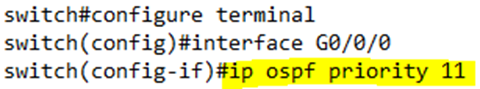
We can change a router’s priority by typing ip ospf priority <priority> on each interface that has OSPF. This ensures that the router with the highest priority wins. We could also change its router ID, but this is not a good idea because we might want to use the router ID to identify the router.
Once a DR and BDR are elected, if the DR fails, then the BDR becomes the DR and the remaining routers elect a new BDR. If a new router enters the subnet, the DR and BDR do not change, even if the new router is better than the existing DR or BDR.
There are two types of OSPF networks: broadcast networks and point-to-point. Most networks are broadcast networks. In a broadcast network, the router advertises its Hello message by sending an Ethernet broadcast frame to the other connected devices.
A Point-to-Point connection can operate as an Ethernet WAN or Ethernet Private Wire, where ethernet frames are transmitted from one router to another through a service provider. On a Point-to-Point connection, we can have OSPF but we will not elect a DR or BDR.
How can we troubleshoot an OSPF connection?
- Make sure that the necessary interfaces are Up/Up – check the interface with the show ip interface command
- Verify that all interfaces are in the same subnet. All routers on a subnet should become neighbors and reach the 2-way state, if not the full state. A router should reach the full state with a DR or BDR.
- Ensure that OSPF is running on both routers.
- Verify that each router has a unique Router ID.
- Verify that there is no firewall or Access Control List that is blocking the traffic and that neighbor authentication is working.
- Ensure that the OSPF enabled interfaces are in the same OSPF area.
- Verify that the Hello and Dead timers are the same on each router.
- When all the settings are correct, and the routers are fully adjacent, they will exchange their LSDBs. If the settings are not correct, the routers will not become neighbors.
One weird exception is that if the network type is different on each router – one router thinks that the network is Point-to-Point while the other router thinks that the network is a broadcast network – the routers will become neighbors and exchange LSDBs, but they won’t add routes to their routing table. That is because one router is expecting to see a DR/BDR and the other router isn’t.