
4.1 Configure and verify inside source NAT using static and pools
NAT or Network Address Translation was a tool created to help the world conserve the very scarce IPv4 addresses until IPv6 was invented.
Three tools were developed to slow the consumption of IPv4 addresses
- NAT
- Private IP addresses
- CIDR or Classless Interdomain Routing
NAT works with private IP addresses.
Think about how massive the internet is. Now imagine that there are some central routers that must send traffic to any part of the internet. Imagine how big their routing tables must be. Those routers need a lot of processing power and a lot of memory to search the table and process every packet, which is not possible.
Thus, we invented CIDR, which allows us to aggregate the different routes. It all started with IANA, or the Internet Assigned Numbers Authority. IANA decided to cut the IP address space into chunks and give each chunk to a different regional ISP.
For example, IANA gave the IP addresses that started with 201 to AT&T. In other words, AT&T is assigned addresses from 201.0.0.0 to 201.255.255.255. AT&T took this address space and subdivided it among its customers. For example, one customer received the network called 201.1.1.0/24, which gave them the addresses between 201.1.1.0 and 201.1.1.255. A second customer received the network called 201.1.2.0/24, which gave them the addresses between 201.1.2.0 and 201.1.2.255, and so on.
The point is that there are 16,777,216 IP addresses in AT&T’s range. In addition, since AT&T is allocating each customer a Class C network, there are 65,536 separate Class C networks in AT&T’s address space.
With CIDR, a major internet router doesn’t need to learn the route to every network, just the major ones. For example, Verizon’s router doesn’t need to learn routes to all 65,536 AT&T networks. If the destination IP address begins with 201, Verizon knows to send the packet to AT&T. AT&T’s router can take that packet and find the appropriate route to the customer’s network.
Remember that IPv4 addresses are scarce. AT&T doesn’t need to give every customer an entire /24 network (256 IP addresses) unless they need it. That might be a waste. Instead of giving them a classful network (an A, B, or C network), AT&T can give them a CIDR block.
For example, we can assign a customer the 201.1.1.32/28 network, which allows them to use IP addresses 201.1.1.33 to 201.1.1.46. Thus, AT&T can split its network into small chunks.
The purpose of NAT is to allow a device without a public unique IP address to communicate over the Internet. NAT works with private IP addresses.
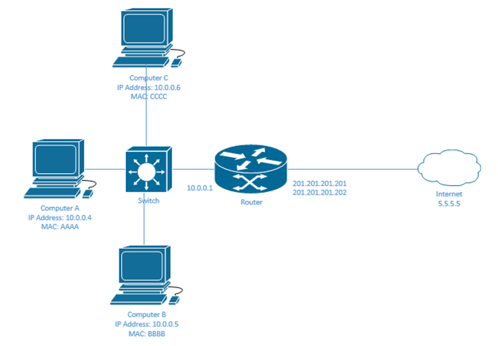
NAT works through a router. In my network, my ISP assigned me only one IP address – 201.201.201.201. This address is given to the public facing interface on my router. I have multiple computers that need to access the internet through the router, but their addresses start with 10. How can they communicate?
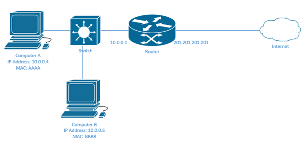
Well, the router must map each external IP address with an internal IP address. Now, if the router had many external IP addresses (enough to provide each internal device with one), we would create a static NAT.
In the following example, I have three internal devices and three external IP addresses assigned to the router. They are trying to access a host on the internet with the IP address 5.5.5.5. Inside the router, I can create a Static NAT Table
| Public IP Address | Private IP Address |
| 201.201.201.201 | 10.0.0.4 |
| 201.201.201.202 | 10.0.0.5 |
| 201.201.201.203 | 10.0.0.6 |
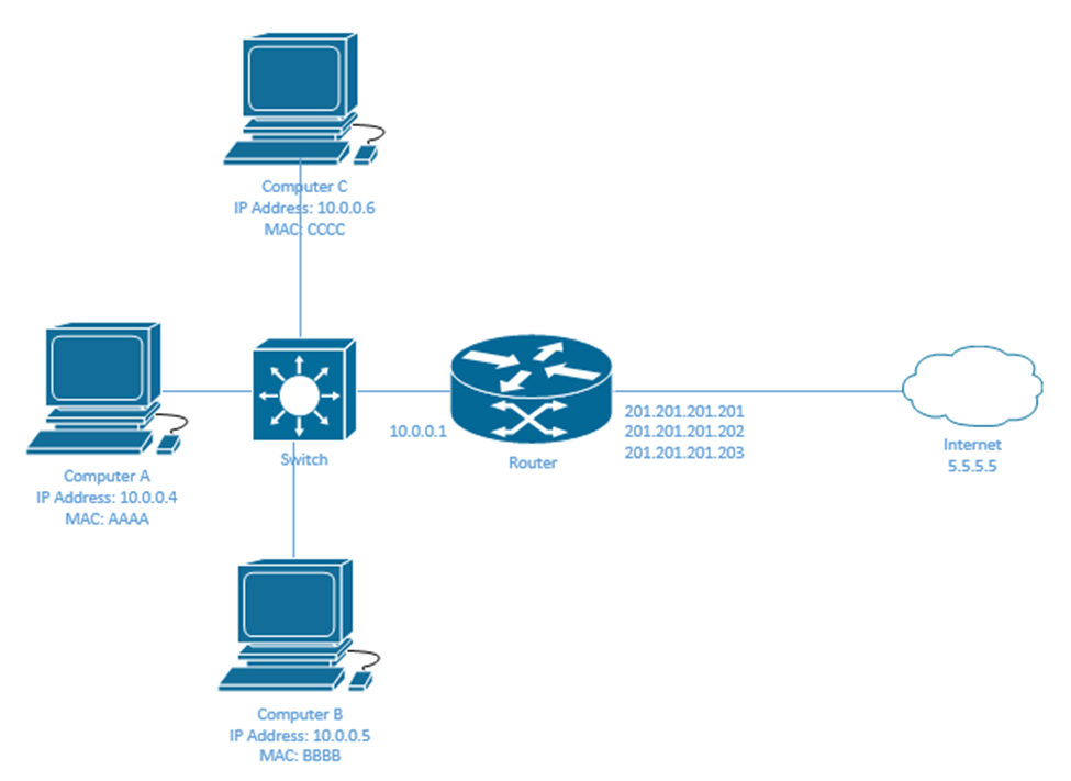
Let’s look the process when Computer A wants to send a message to a device on the internet with the IP address 5.5.5.5?
- Computer A realizes that its IP address is 10.0.0.4 and that 5.5.5.5 is in a different subnet. Therefore, it sends its packet to the router’s LAN IP address, 10.0.0.1. We already learned how frames are routed through a local network.
- The source IP on the packet is 10.0.0.4 and the destination IP is 5.5.5.5
- The router checks the Static NAT Table. It finds out that public IP 10.0.0.4 is mapped to 201.201.201.201.
- The router changes the source IP address to 201.201.201.201 and forwards it out of its external interface. We already learned how the router finds the route to an external network.
- The server at 5.5.5.5 receives the packet.
- The server replies to Computer A, but it puts the destination address as 201.201.201.201, because it doesn’t know about the 10.0.0.4 IP address. It has no visibility inside the 10.0.0.0/24 network on the left.
- The router receives the reply on its external interface.
- It checks the table and finds that 201.201.201.201 is mapped to 10.0.0.4.
- It changes the destination IP address to 10.0.0.4 and forwards the packet to Computer A through its internal interface.
Cisco calls the private IP addresses inside local IP addresses, and the public IP addresses inside global IP addresses. The external device IP addresses are called outside global IP addresses.
We are only worried about changing the IP address of our internal devices, not the external ones. It is possible to create a NAT for external devices but that isn’t a concern in the CCNA.
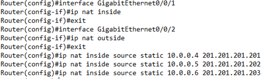
We must configure the static NAT on each interface that will see traffic involving the NAT. We need at least two interfaces – an inside and an outside.
Enter the interface configuration and type ip nat inside or ip nat outside depending on whether the interface is inside or outside the local network.
Go back to global configuration mode and type ip nat inside source static <inside local IP address> <inside global IP address> for each static IP mapping.
My configuration would look like this
I can verify the NAT static mappings by typing show ip nat translations. I can verify the statistics by typing show ip nat statistics.
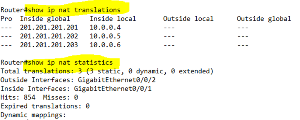
The hits tells us how many packets have been translated by NAT.
The problem with this example is that IPv4 addresses are scarce. We might have hundreds of computers, but our ISP is unwilling to provide us with hundreds of IP addresses. Thus, we can use a dynamic NAT. How does it work?
I only have two public IP addresses, but at least three internal devices. Thus, I don’t map any IP addresses to any devices.
I instead create a NAT Pool, which contains my available public IP addresses.
| Pool |
| 201.201.201.201 |
| 201.201.201.202 |
My NAT table is empty
| Public IP Address | Private IP Address |
- If computer A wants to send a message to 5.5.5.5, it again realizes that the destination is not in its subnet. It creates a packet and sends it to the router.
- The router realizes that Computer A needs a public IP address. It chooses an IP address from the pool and assigns it to Computer A. Now my NAT table has an entry and there is one IP address left in the pool.
| Public IP Address | Private IP Address |
| 201.201.201.201 | 10.0.0.4 |
- Like before, the router changes the source IP address of packets coming from Computer A to the public IP of 201.201.201.201. It also changes the destination IP address of packets travelling to Computer A from 201.201.201.201 to 10.0.0.4 and forwards them out of its local interface.
We can configure a dynamic NAT like a static NAT.
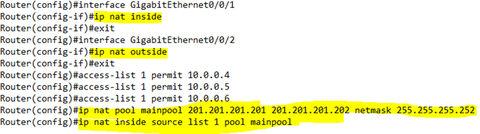
Again, we enter the interface configuration and type ip nat inside or ip nat outside depending on whether the interface is inside or outside.
We must create an ACL (Access Control List) that matches the local IP addresses whose traffic should be translated by NAT. We will learn more about ACLs later.
We establish a NAT Pool by typing ip nat pool <Pool Name> <First IP Address> <Last IP Address> netmask <subnet mask>.
Finally, we create the NAT by typing ip nat inside source list <ACL Number> pool <Pool Name>, where ACL Number is the number of the ACL we created earlier, and the Pool Name is the name of the Pool we created earlier.
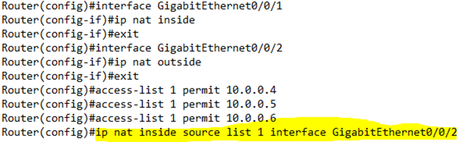
In my example, we set G0/0/1 as the inside NAT interface, and G0/0/2 as the outside NAT interface. We created ACL 1 to permit access to 10.0.0.4 through 10.0.0.6. The router recognizes that internal devices with IP addresses 10.0.0.4 through 10.0.0.6 match ACL 1.
Then we created a NAT pool with the range of 201.201.201.201 to 201.201.201.202 and called it mainpool.
Then we told the router to use ACL 1 and the NAT pool mainpool. Now the router knows that traffic entering G0/0/1 from devices 10.0.0.4 through 10.0.0.6 should be assigned an IP address from the range of 201.201.201.201 to 201.201.201.202 if it is leaving the G0/0/2 interface.
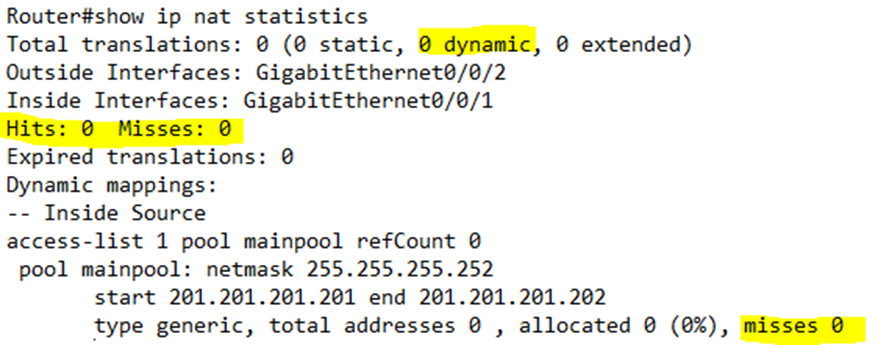
I can verify the NAT dynamic mappings by typing show ip nat translations. I can verify the statistics by typing show ip nat statistics.
Note that until the router begins to exchange traffic, there will be no dynamic mappings and the show ip nat translations command will return nothing.
The statistics show two misses counters. The first counter tracks missed packets across all forms of NAT in the router, while the second counter tracks missed packets among the specific NAT dynamic pool we created.
After we start exchanging traffic, we see that our router assigned both IP addresses in the pool, and that it exchanged some traffic.
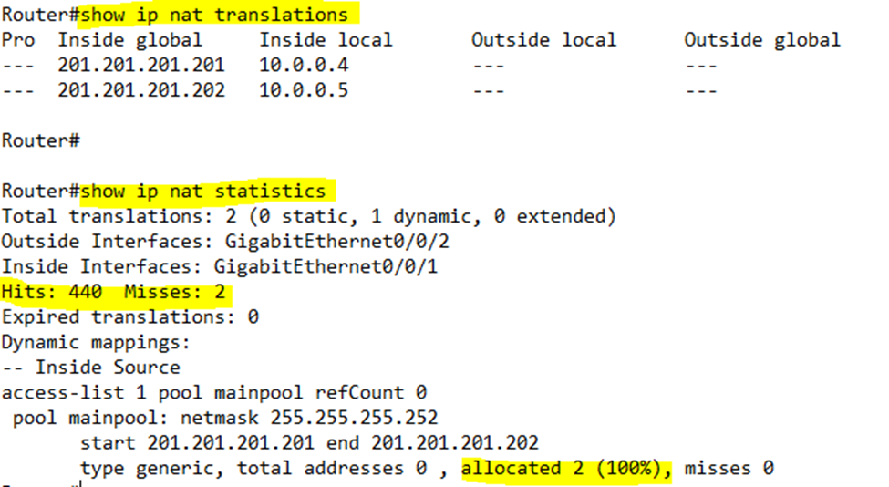
Notice that I have two misses in the first counter but none in the second counter. The first time 10.0.0.4 sent a packet, the router received the packet but didn’t have a NAT IP address allocated to it, so it dropped the packet and created a mapping. Thus, it registered a miss. The first time 10.0.0.5 sent a packet, the router did the same thing. The second time 10.0.0.4 and 10.0.0.5 sent packets, the router already had a mapping, so it was able to forward their traffic.
If the router notices that an IP address from the pool hasn’t been in use for a while, it returns it to the pool so that it can be given to another device. But if all the addresses are in use and another device wants to send traffic out to the internet, it must wait until an address becomes available. This could take seconds or minutes or even days. What if we have a large office with hundreds of employees who need to access the internet, and only two IP addresses?
We can use NAT Overload also known as Port Address Translation, or PAT.
In my next example, I only have one public IP address and three computers that want to talk at the same time.

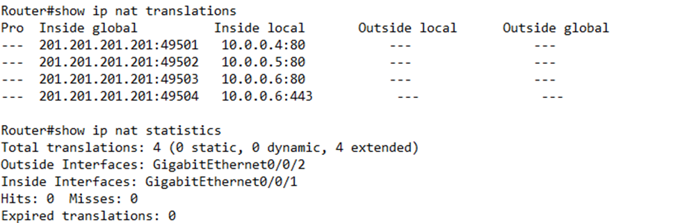
Now I need to look at the IP port used by each device. Let’s say that each computer is attempting to access a website on Port 80. The full address of the website is 5.5.5.5:80.
Computer A, B, and C realize that 5.5.5.5 is not in their subnet so they send their traffic to the router. Their addresses are
- Computer A – 10.0.0.4:80
- Computer B – 10.0.0.5:80
- Computer C – 10.0.0.6:80
The router only has one address – 201.201.201.201. Thus, it creates the following mapping
| Public IP Address & Port | Private IP Address & Port |
| 201.201.201.201:49501 | 10.0.0.4:80 |
| 201.201.201.201:49502 | 10.0.0.5:80 |
| 201.201.201.201:49503 | 10.0.0.6:80 |
The router gave each local device the same IP address but a different port. It chose ports 49501 to 49503, which are ports that aren’t used for common applications. The actual port numbers aren’t too important.
When the router receives traffic from 10.0.0.4:80, it knows to change its source IP address/port to 201.201.201.201:49501, and when the router receives traffic with a destination of 201.201.201.201:49501, it changes its destination/port to 10.0.0.4:80.
What if Computer A is also sending traffic over HTTPS (port 443)? The router assigns it the same external IP address and another port. Remember, the router assigns a port when it sees traffic that requires it. It doesn’t do so proactively. Now our table looks like this.
| Public IP Address & Port | Private IP Address & Port |
| 201.201.201.201:49501 | 10.0.0.4:80 |
| 201.201.201.201:49502 | 10.0.0.5:80 |
| 201.201.201.201:49503 | 10.0.0.6:80 |
| 201.201.201.201:49504 | 10.0.0.4:445 |
Using NAT Overload, we can map tens of thousands of ports to one IP address. A single computer on our local network might use between 5 and 15 ports. Thus, we can support thousands of computers with one public IP address.
We can configure NAT overload like dynamic NAT.
Again, we enter the interface configuration and type ip nat inside or ip nat outside depending on whether the interface is inside or outside.
We must create an ACL that matches the local IP addresses whose traffic should be translated by NAT.
Finally, we create the NAT by typing ip nat inside source list <ACL Number> interface <Interface> overload, where ACL Number is the number of the ACL we created earlier, and the Interface is the external interface that NAT will operate on. NAT will automatically use the IP address of the interface that it is assigned to.
I can verify the NAT overload mappings by typing show ip nat translations. I can verify the statistics by typing show ip nat statistics.
What could possibly go wrong?
- We have the wrong inside and outside commands applied to each interface. For example, we set our inside interface as an outside interface. Or we set an interface as inside but it isn’t connected to the LAN.
- We don’t have the correct range of IP addresses configured.
- We don’t have the correct ACL configured, or an internal address that should have its packets translated is not part of the ACL.
- The pool has run out of IP addresses in dynamic NAT.
- We configured PAT but did not choose the correct interface.
- We have another ACL that is blocking the traffic.
- We created the NAT correctly, but no traffic is coming to the router for some other reason.
First make sure that the packet is leaving the user’s computer and reaching the correct internal interface on the router. Then make sure that the router has a correct NAT translation using the show commands. Then make sure that the router is transporting the packets out of the correct interface.