
4.2 Configure and verify NTP operating in a client and server mode
NTP or Network Time Protocol makes sure that every device on the network has the same time, even when they are in different time zones.
If routers and switches don’t synchronize their clocks, then their messages will have the wrong time stamp and none of them will be able to determine when a message was sent or received. When two network devices communicate, they exchange NTP messages and synchronize their clocks. Eventually, as more and more devices exchange NTP messages, their clocks get closer to the real time.
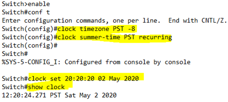
The first thing we must do is set the correct time zone and daylight savings time.
- clock timezone <Time Zone Name> <UTC Time Offset>
- The Time Zone Name can be any meaningful name we choose.
- The UTC Time Offset is between -12 and +12 depending on the time zone that we are in. For example, Pacific Time is -8. If we are in the Pacific time zone, we type clock timezone PST -8.
- clock summer-time <Time Zone Name> recurring
- The Time Zone Name can be any meaningful name we choose.
- We type recurring to make sure that the router changes the time based on daylight savings time each spring and fall.
We can set the time with clock set <time> <date>.
We can view the time with show clock. The switch will accept the time that we entered in 24-hour format as UTC time, and then convert it to the local time zone. Notice that I entered “20” for the hour, but the switch converted it to “12 PST”, which is the eight-hour time difference.
Now that we’ve configured a reasonably correct time, we need to set up the Network Time Protocol.
There are two methods
- NTP Master. A device that is an NTP Master has an internal clock. It tells other devices what time it is, but other devices can’t tell it what the time is.
We configure it with ntp master <level>. This level is known as a stratum. - NTP Server. A device that is an NTP Server tells other devices what time it is, but other devices can tell it what time it is. It can accept a time update from a device with a more accurate time, and then it can send time updates to other devices.
We configure it with ntp server <IP address or hostname> and specify the IP address or hostname of an external server that can provide us with the time. Cisco recommends that we configure at least three external servers so that we can obtain an accurate time.
We can verify the status by typing show ntp status.
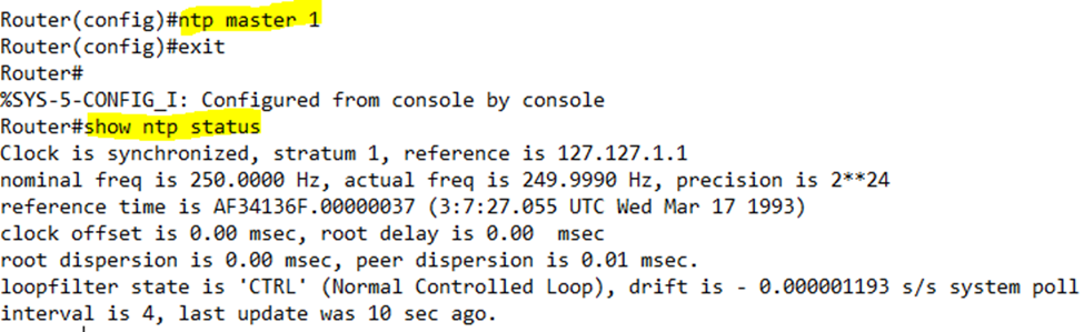
The status tells us that the Clock is synchronized and provides the reference. The reference is the IP address of the source of the time (typically another router). In this case, our router is the master, so the source of the time is itself (127.127.1.1).
If we type show ntp associations, we can obtain a list of other NTP servers that the router is attempting to connect to.
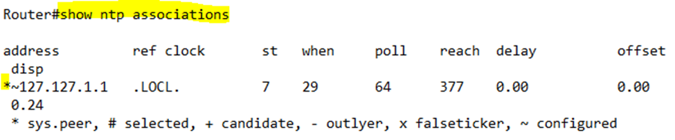
A * in front of an entry indicates that the router was successful in obtaining a time stamp from the server.
The stratum level is the hierarchy of the NTP server. A level of one is the highest. The most master server has a stratum of one. A server with a stratum of one gets its time from its own internal hardware. The higher the stratum, the more accurate the time is assumed to be.
Any client that obtains its time from a server adds one to the level. For example, if our server has a stratum of two, when our clients obtain the time from it, they change the stratum level to three. Any devices obtaining the time from those clients change the stratum level to four, and so on.
Each time a device obtains a time from another server, the accuracy of the time decreases. A time stamp with a stratum of four has been passed through three routers, so it is considered less accurate than a time stamp with a stratum of two or three. The stratum level helps us determine how accurate a time stamp is.
The stratum level can be between one and fifteen. A time stamp with a level of 16 or higher cannot be trusted. The default stratum is eight.
The government runs some NTP servers that are available for the public to use. We don’t need to run our own time server unless we have an air-gapped network.
We type ntp server <external server name> to use an external NTP server.
For example, ntp server time-a-b-nist.gov allows our device to obtain the time from the NIST server.
A better solution is to create a master NTP server on our network. The server can be a device such as a router or switch.
- This server is synchronized with the external clock by typing ntp server <external server name>, which is very accurate.
- We also synchronize it with the internal clock by typing ntp master <level>, so that our network continues to maintain an accurate time if access to the external NTP server fails.
- We must make sure that the NTP master level is higher than that of the external server so that the internal server relies on the external server for its time first.
A router loopback interface is an internal interface that exists if the router is up, and the loopback is not shutdown.
We can configure a loopback interface by typing interface loopback <number>. We can pick any number for the interface. As soon as we enter the loopback interface configuration, the router creates the interface.
Why do we want to configure a loopback? We can give it an IP address and pretend that it’s a physical interface. But it’s a physical interface that doesn’t shut down because it doesn’t physically connect to anything.
A router might be reachable through more than one physical interface. If an NTP client (another device on the network that wants to know what time it is) uses a specific interface to reach the router, and that interface fails, the NTP client won’t be able to obtain a timestamp from the router, even if other interfaces remain reachable.
One benefit of creating a lookback interface inside the router is so that we can always reach it as long as one physical interface is working. After we create the interface we then change the NTP Source inside the router to the loopback IP interface with the ntp source loopback <loopback number> command.
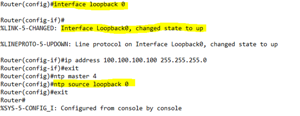
After we created the loopback interface with an ID number of 0, the interface automatically came up. We then specify an IP address (100.100.100.100) for the interface. Finally, we set the NTP source to be the loopback 0.
On our client, we reference the NTP loopback IP address by typing ntp server 100.100.100.100. Now we can reach the router via NTP regardless of which interface is active. Why does this work? The router creates an internal route to the loopback IP from all of its external physical interfaces. Thus, we can always reach the loopback interface.