
4.7 Explain the forwarding per-hop behavior (PHB) for QoS such as classification, marking, queuing, congestion, policing, shaping
Quality of Service or QoS is a tool that allows our network to prioritize certain types of traffic. The actions apply when the data is inside the device – that is between the time that it enters a device and the time that it leaves. These actions are called per-hop behaviors or PHBs.
We want our traffic to arrive on time and we want it to arrive accurately. There are four things we monitor
- Bandwidth. That is how fast our connection is. It’s the capacity of our connection. We should divide our bandwidth among different types of traffic so that each one gets its fair share instead of allowing some forms of traffic to overwhelm our internet connection. We can assign a different proportion of bandwidth to each type of traffic.
- Delay is the time that it takes for a packet to get from its sender to its destination. We can measure the one-way delay, or the round-trip delay. Delay is also known as latency.
- Jitter is the difference in the one-way delay between different packets. If we send some packets, 1 second apart, we expect them to arrive on the other side one second apart. If they arrive too far apart, we will experience a drop in the connection quality. If they arrive too close together, we might overload the buffer.
- Loss is the number of packets that do not arrive at their destination. It is typically expressed as a percentage.
Imagine a highway from New York to Los Angeles. The bandwidth is like the number of lanes on the highway. The speed limit is fixed, so if we want to increase the number of cars arriving per minute, we must add more lanes.
The delay is the time it takes for a car leaving New York to arrive in Los Angeles. The delay could be affected by traffic jams, congestion, accidents, etc.. If part of the road is blocked or has fewer lanes open, the cars don’t arrive on time. In a computer network, if some equipment has failed or is overloaded, the packets don’t arrive on time.
The jitter is the delay between car arrivals. If the cars leave New York one minute apart, we expect them to arrive in Los Angeles one minute apart, and in the same order.
Loss is the number of cars that don’t arrive at all.
We want to provide each user with the best possible experience, but we also want to make sure that business-critical applications are given priority. This is known as Quality of Experience or QoE.
Delay and Jitter are more important in interactive applications such as Remote Desktop Connections, websites, and VoIP. They are less important for non-interactive applications such as file transfers, which may require more bandwidth.
Think about a file transfer like sending a book through the mail. We rip out every page and send it as a separate packet. The recipient doesn’t care if the pages arrive in the wrong order because they have page numbers and he can put them back together when they all arrive. The recipient can’t do anything with the book until every page arrives. If any pages go missing, the sender can resend them.
Now think about a video call or a phone call. Every word is sent as a separate packet. The recipient’s computer must play the packets back in real time, as they arrive. If the packets arrive in the wrong order, then the words that you say will be played back in the wrong order. If the packets arrive late, then there will be a delay when you are speaking. If the packets don’t arrive at all, then the recipient won’t be able to hear some of your words. The recipient can’t wait until all the packets arrive and then try to play them back in the correct order, and the recipient can’t ask the sender to send them again because the phone call is live.
VoIP and video applications do have some error correction mechanisms, but they can only go so far.
For a VoIP call, we need
- 80 kbps of bandwidth
- A one-way delay of less than 150 ms
- 30 ms or less of jitter
- A 1% packet loss or less
For a Video call, we need
- Between 384 kbps and 20 Mbps of bandwidth depending on the quality, type of video, and compression. Videos with lots of movement require more bandwidth.
- A one-way delay of less than 200 ms to 400 ms
- 30 ms or less of jitter
- A 1% packet loss or less, and ideally a 0.1% packet loss
The first thing that a network device does is it examines the packet’s header to determine what kind of data is inside. This is called classification. The network device maintains several queues, one for each type of traffic. It puts each packet in the appropriate queue and transmits them based on their priority.
For example, we have a VoIP queue that support 100 packets/second, and a data queue that supports 10 packets/second. If 100 VoIP packets, and 50 data packets arrive, the VoIP packets are sent out immediately, but the data packets get stuck in the data queue for up to five seconds (the first ten are sent out immediately, ten more in the next second, etc.).
Every time the packet enters or exits a device it can be classified. But a packet might pass through dozens of interfaces along its journey. A more efficient solution is to classify the packet once, as close to its creation as possible and mark it. Marking is the process of changing the packet’s header so that other devices know what level of service to apply to it.
The marking is called the DSCP or Differentiated Service Code Point. Other devices downstream read the DSCP value and understand what level of service to provide it.
Inside the IPv4 header is a portion called the Type of Service, or ToS, and that is where the DSCP goes. We can give it a number from 0 to 63. We mark the IP header because it stays with the packet from the beginning of its journey to the end, unlike the Ethernet header
In IPv6, the marking location is called the Traffic Class.
The other area that we can use to mark a packet is the Ethernet Frame. Inside the Ethernet Frame is a field called the 802.1Q section. We call this the Class of Service (CoS) or Priority Code Point (PCP). We only use the 802.1Q section on an ethernet frame that is being passed over a trunk port. Thus, the CoS only stays on frames that are travelling through a trunk.
QoS can work with an ACL. If traffic from specific devices such as VoIP phones or video conferencing equipment must be prioritized, and those devices sit in specific ranges of IP addresses, we can configure an ACL.
If an ACL doesn’t fit our needs, we can use Cisco Network Based Application Recognition, or NBAR. The second variation of NBAR is called NBAR2, which can look inside the contents of each packet to determine the type of traffic it is carrying. NBAR can match over 1000 types of applications because each one has a unique application signature.
On a router, we can enter NBAR configuration by typing class-map matchingexample.
The problem is that just because your network trusts a QoS marking in a header doesn’t mean that others will too. Otherwise, an end user could mark all his packets as having a high priority and override the wishes of the network administrator. Thus, we create a trust boundary that determines where we start to trust QoS markings. The trust boundary typically starts at an edge switch in our internal network (after traffic has left the end user devices).
When we use IP passthrough with a VoIP phone, the VoIP phone acts like a mini switch and can perform the marking. Thus, we would set the VoIP phone as the trust boundary.
What one network considers “priority 1” could be “priority 2” or “priority 3” in a different network. For multiple networks to be able to understand each other’s QoS markings, DiffServ was developed.
DiffServ is an architecture with recommended DSCP values for different types of traffic, allowing multiple networks to create consistent markings. There are several sets of DSCP values
- Expedited Forwarding or EF is a marking for packets that require low delay, low jitter, and low loss. The DSCP value is 46. Voice traffic is typically marked as EF. By default, a Cisco IP Phone will mark voice traffic with EF. EF is the highest priority of traffic.
- Assured Forwarding or AF is a set of 12 DSCP values that fit into a table. There are four separate queues, and three separate drop priorities. When combined, we get 12 different values.
AF41, AF41, and AF43 (known as AF4x) are used for video conferencing.
AF31, AF32, and AF33 (known as AF3x) are used for streaming video.
AF21, AF22, and AF23 (known as AF2x) are used for data that requires low latency.
To the left of each bracket is the DSCP value and to the right is the AF value. The drop priority is how likely a router is to drop the packet when it is too busy.
| Best Drop | Moderate Drop | Worst Drop | |
| Best Queue | 34 (AF41) | 36 (AF42) | 38 (AF43) |
| Moderate Queue | 26 (AF31) | 28 (AF32) | 39 (AF33) |
| Lower Queue | 18 (AF21) | 20 (AF22) | 22 (AF23) |
| Worst Queue | 10 (AF11) | 12 (AF12) | 14 (AF13) |
- Class Selector or CS values. The ToS is a 3-bit IP Precedence field or IPP. DiffServ uses the ToS field to hold a DSCP value called the Class Selector. The CS values are from CS0 to CS7. CS values are used for normal data.
DiffServ values are open source, but Cisco encourages us to use them. Cisco devices use the DiffServe standard by default.
I mentioned queues earlier. A queue is a line up of packets that are waiting to be sent. We make the packets line up just like at the airport, in different classes. Regardless of the queue, all the packets must leave through the same interface. But we let more packets out of the higher priority queues than out of the lower priority queues. This is called prioritization. There are several prioritization algorithms
- Round Robin. In the round robin, the router takes a packet from the first queue and then one from the second queue and then a packet from the third queue, and then so on. The router takes a packet from each queue in order, and no queue is given priority.
- Weighted Round Robin. We can give each queue a weight. For example, we take five packets from the first queue (the VoIP queue), and then two packets from the second queue (video queue), and then one packet from the third queue (data queue). This ensures that more important traffic is given priority and but also that each type of traffic is given an opportunity to transmit.
A tool that helps with ensuring that all traffic is given a share of the bandwidth is called the Class-Based Weighted Fair Queuing or CBQFQ. We configure each queue to have a specific percentage of the bandwidth. For example, the VoIP queue is given 50% of the bandwidth, the video queue is given 30% of the bandwidth, and the data queue is given 20% of the bandwidth. - The problem with a Weighted Round Robin is that some types of packets can’t wait in a queue, even if all the packets are eventually sent out. For example, the router should send out voice traffic as soon as it receives it. We can use LLQ to specify some queues as priority queues. Traffic from a priority queue is always sent out as soon as it is received, no matter how full the other queues are. When the router is not sending traffic from a priority queue, it runs the round robin on the other queues.
If the priority queues occupy all the bandwidth on the interface, then the router will never get to the other queues. This is called queue starvation. We can avoid queue starvation by using queue policing. We simply limit the amount of bandwidth a priority queue can use so that other queues have a chance. This could cause the router to discard some of the priority traffic. If we discard only a small portion of the priority traffic, the end users may not notice. - Call Admission Control or CAC is another tool that helps us send out the priority traffic as it arrives, without discarding any of the traffic.
How can we create a good QoS strategy?
- If we don’t have enough bandwidth to support all our applications, we must separate each type of traffic into a separate queue.
- We give more important types of traffic higher priority.
- We use a priority queue for voice and video traffic so that the packets are sent out as soon as they arrive. Voice traffic should have a separate queue from video traffic.
- The voice and video traffic should be given enough bandwidth so that the router does not drop any of their packets.
- We use a round-robin queue for other types of data.
- Use the CAC tool to prioritize voice and video traffic if necessary.
Traffic policing and shaping helps us limit traffic by setting a rate for each type of traffic. The router monitors the rate of traffic. Each time a new packet arrives, the router determines whether it will cause the router to exceed the rate that was set.
If the rate will not be exceeded, the router lets the packet through.
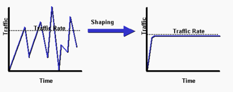
If the rate will be exceeded, and traffic shaping is enabled, the router queues the packet. If the rate will be exceeded, and traffic policing is enabled, the router drops the packet.
With policing, the traffic isn’t allowed to exceed a specific rate. Policing might allow the traffic to exceed the specified rate for a brief period (this is called bursting).
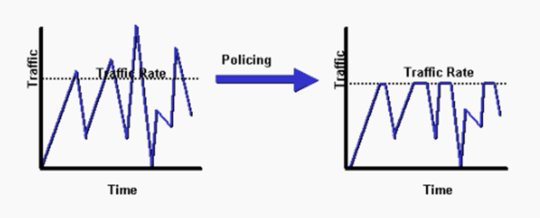
Traffic Policing is used by Internet Service Providers to limit the amount of bandwidth a customer can send over a connection. For example, if we are paying for a 10 Mbps connection, the service provider might drop any traffic that exceeds that rate unless we paid for more bandwidth.
Instead of dropping the extra packets, we might choose to mark them as low priority and let them through. If the network has ample resources, we transport the packets received above the policing limit because it doesn’t cost us anything. When the network gets congested, we drop any packets that are marked as low priority so that other clients can pass their traffic.
With shaping, we set a specific data rate. When additional packets arrive that would cause us to exceed the rate, we put them in a queue and hold them until they can be sent. For example, if our rate is 10 Mbps, and we’re receiving traffic at a rate of 11 Mbps, some of it is stored in the queue until the rate drops below 10 Mbps. If we’re receiving traffic at a rate of 9 Mbps, we don’t need to make any changes.
Traffic shaping causes jitter and delays while some packets are waiting. We can configure the traffic shaper to apply on less important traffic so that voice and video traffic is unaffected.
Over time, the traffic shaper is designed to maintain traffic at a specific rate, called a time interval. If our rate is 10 Mbps, then we can only send 10 Megabytes every second. What if our interface speed is 100 Mbps? The traffic shaper would send the 10 Megabytes at the beginning of each second. It would take 0.1 seconds to send 10 Megabytes out of a 100 Mbps interface. That means that the interface is idle for the next 0.9 seconds. Then it is ready to send traffic out again.
This would be a problem for voice traffic because the maximum delay is 150 ms, and our traffic could be delayed up to 1 second (1000 ms). It is recommended that we use a time interval of 10 ms or less for traffic shaping when voice or video applications are involved. That means that a voice packet won’t be slowed down by more than 10 ms because of traffic shaping. Instead of setting our rate as 10 Megabytes per second, we would set it as 0.1 Megabytes per 10 ms. Now our interface sends traffic 100 times per second instead of one time per second.
TCP has a tool called windowing, as mentioned earlier. During a TCP connection the recipient gives the sender a window size. The window size tells the sender how many packets he can send before having to wait for the recipient to acknowledge receipt. If the window size is five, then the sender sends five packets and waits. The sender won’t send any more packets until the recipient acknowledges receipt of the first five.
Each time a recipient acknowledges receipt of a message, it also sends a new window size to the sender. If the transmissions are going well, the recipient continues to increase the window size. Eventually, the window size is so big that the data flows in a continuous stream and the sender never stops sending.
If the transmissions are not going well (if packets are being lost), the recipient begins to decrease the window size to slow it down.
The problem is that a queue in a router has a limited capacity. If we experience congestion, the queue fills up with data and the router has no more place to put the data, so it starts dropping the additional traffic. This is called a tail drop.
We can use a congestion avoidance tool like windowing to reduce the amount of traffic coming in to the router. Downstream that lets us avoid filling up the router queues.
When the queues are empty, we operate like normal. When the queues are full, we drop all new traffic. This is known as the maximum threshold. To avoid reaching a state with full queues, we begin dropping a percentage of traffic when the queues have filled past a certain percentage. This is known as a minimum threshold. For example, if our minimum threshold is 70%, we might drop 10% of incoming traffic when the queues are 70% full. We do not drop all packets at the same rate. Remember that we have classified each packet with its DSCP value. We can drop a higher rate of less important traffic.