
6.2 Compare traditional networks with controller-based networking & 6.3 Describe controller-based and software defined architectures (overlay, underlay, and fabric)
6.3.a Separation of control plane and data plane
6.3.b North-bound and south-bound APIs
A Software Defined Network or SDN is also known as Software Defined Architecture or SDA, Programmable Networks, or Controller-Based Networks.
With an SDN, we don’t need to worry about manually configuring each device and each interface. We draw out a policy framework, and the controller configures the underlying devices. This is faster and reduces errors.
Earlier, I spoke about the data plane and the control plane. The data plane carries user traffic while the control plane carries configuration and monitoring for the network devices. The control plane operates the protocols that help the data plane function.
What does the data plane do?
- Adds and removes Ethernet headers and trunk headers
- Adds and removes IP headers
- Decides how to forward a frame based on its MAC address
- Decides how to forward a packet based on its IP address
- Operates Network Address Translation
- Encrypts and decrypts data
- Establishes a VPN connection
- Enforces the Access Control Lists, Port Security, DHCP Snooping
What does the control plane do?
- Manages ARP
- Manages Spanning Tree Protocol
- Manages Neighbor Discovery Protocol
- Allows a switch to learn MAC addresses
- Manages routing protocols such as OSPF, EIGRP, and BGP
The management plane allows us to configure and monitor the network devices. It includes
- Telnet
- SSH
- SNMP
- Syslog
Inside the switch is a circuit called the Application-Specific Integrated Circuit or ASIC. The ASIC is a custom-designed circuit that only knows how to forward ethernet frames by checking the switch’s MAC address table. We use an ASIC because standard hardware won’t perform as efficiently. This is important because the switch might be forwarding millions of frames per second.
The MAC address table is stored inside the ternary content-addressable memory, or TCAM. The TCAM is a special type of memory that lets us search the table instantly. If we give the TCAM a MAC address, it gives us the matching entries instantly.
The idea now is to use a Software Defined Network to centralize the control of our network. In a traditional network, the control plane is distributed across all the devices. That means that every router or switch makes its own decisions. For example, every router makes its own decisions about forwarding packets, and each switch makes its own decision about forwarding frames.
A centralized control plane can be more efficient. We use a SDN controller. The amount of centralized control varies from network to network. The controller can be anywhere in the physical network, but it must be able to reach every network device.
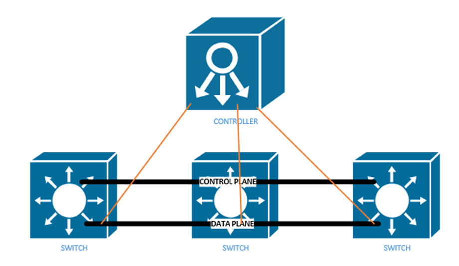
In a controller there are two interfaces
- The Southbound Interface or SBI is the interface between the controller and its devices that it controls. Its name comes from the fact that in network diagrams, the controller sits above the devices that it controls.
The Southbound Interface is not just a physical interface, but also a set of protocols that allow the controller to control network devices. It might also include an API or Application Programming Interface. An API lets two different programs talk to each other. The developer of each program creates a common set of instructions or words that one program can use to talk to another program.
There are many different models of SBIs. The official Cisco SBI is called OpFlex. Other programs include OpenFlow, Telnet, and SNMP. - The Northbound Interface or NBI allows us to read the data inside the controller. We can send commands to the controller, and the controller can send commands to the network devices that it manages.
Technically, the controller can be a software program that is on a server. Another application can connect to the controller via an API. We can create programs or workflows that interact with the controller for monitoring, filtering, or controlling traffic.
A REST API or Representational State Transfer API is one that allows different APIs to exist on different physical devices. The APIs communicate via HTTP or HTTPs messages. We communicate with a Rest API by visiting a specific URL. We will see some examples further in this section.
An API is designed to return structured data. If we understand the format of the data that we will receive, we can write a program to interpret it. The two main API languages are JSON or JavaScript Object Notation and XML, or eXtensible Markup Language.
Our Application sends the Controller a request over its API by sending a message called an HTTP GET URI. The Controller replies with an HTTP GET Response, which includes the data.
There are three main controllers: OpenFlow, OpenDaylight, and Open SDN.
The Open Networking Foundation produces an open-source Software Defined Networking framework called OpenFlow. The Foundation works with many network engineers and vendors of network equipment so that they can help create an SDN framework that works on all devices. That means any brand of network equipment can work with any other brand of network equipment.
OpenFlow defines network devices as abstract ideas with standard capabilities. For example, the idea of a switch is a device that forwards traffic based on its destination MAC address. Most of the control plane is centralized by OpenFlow. The controller and applications that talk to the controller control the network.
The OpenDaylight Controller is an open-source controller based on the ONF Framework. Any SDN controller vendor can use the OpenDaylight Controller as the basis for their own commercial controller. The controller supports several SBIs including BGP and OpenFlow. Any vendor can take this controller and customize it for their own use.
Cisco’s version of the OpenDaylight Controller is called the Open SDN Controller, or OSC, but it is no longer available. The current version is called the Software-Defined Access or SDA and the Software-Defined WAN or SD-WAN (SD-WAN is supported by many other vendors).
When designing an SDN, instead of thinking about the physical layer (Layer 1) of the OSI model, we should focus on the application layer (Layer 7). What resources do applications on Layer 7 need to function? Once we understand that, we can build a network to support them. We call this Application Centric Infrastructure or ACI.
One feature of the new software defined network is not worrying about manually configuring each physical interface. Remember from our earlier part of the book that on a single switch interface, we can give it a speed, duplex, description, ACL, VLAN, make it trusted or untrusted, etc. Across an entire network, we may have thousands or hundreds of thousands of switch ports.
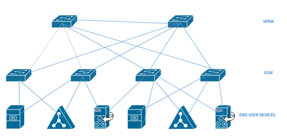
Going back to the beginning of the book, I talked about a Spine Leaf topology. We also call it a Clos network. Each leaf switch is connected to each spine switch, but no leaf switches connect to each other, and no spine switches connect to each other. An end user device connects to a leaf switch. Most of the end user devices will be routers and servers. An end user device can connect to multiple leaf switches.
An Application Policy Infrastructure Controller or APIC controls the ACI. ACI uses an Intent-Based Networking model, or IBN. Instead of manually configuring each switch interface, we create some policies that tell the network what type of devices can communicate. The controller analyses these policies and configures the physical network hardware to match the intent of the policies. If we move equipment to other physical locations within the network, the ACI reconfigures the hardware so that it continues to match the intent of the policies.
Think about a large website like Amazon.com
- It has a front-end website that serves the product catalog, pages, reviews, etc.
- It has a content delivery network that provides product photographs, videos, etc.
- It has a database that holds product information, reviews, etc.
- It has a payment application that processes credit cards.
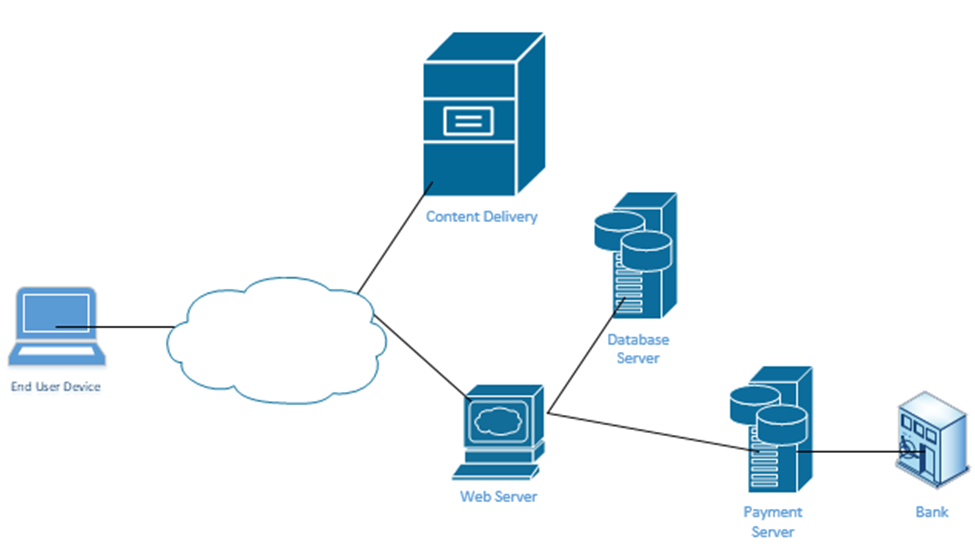
When you visit the website, your computer requests a specific page from the Web Server. Every Amazon product page is just a template. Amazon’s server figures out the product number of the page that you visited and calls up a database that contains the product’s price, properties, and reviews. It fills out the product page template and sends it to your web browser. The page also includes links to photographs. Your web browser manually downloads the photographs from Amazon’s content delivery network and inserts them into the page.
At no time should you be able to directly connect to Amazon’s database – only to its web server and content delivery network. If Amazon uses a controller, it can create these kinds of policies on its network. For example, it would create a policy that allows only web servers and database administrators to connect to its database server.
It’s not that our switch doesn’t have VLANs, access ports, trunk ports, speeds, duplex, or security settings. But we don’t have to worry about it anymore. We just create policies and the APIC creates all the configurations.
In an Enterprise network, we can use the APIC Enterprise Module or APIC-EM. One problem is that many networks have legacy devices that don’t support SDN. Cisco knew that a customer would not purchase an SDN if they had to replace all the underlying network hardware such as switches and routers, thus they introduced the APIC-EM. It allows us to keep the same equipment but configure it via an SDN controller instead of via Telnet, SSN, or a console cable.
What can the APIC-EM do?
- It allows us to automatically map out the topology of our network
- It can show us how data flows through our network (if we provide it with a source and destination, it can create a diagram demonstrating the pathway)
- It can show us how the network makes forwarding decisions at each router or switch interface
- It allows us to automatically configure new devices as soon as they are connected to the network
- It allows us to manage Quality of Service
APIC-EM can’t automatically configure any devices that do not support automatic configuration, but it can automatically configure them via Telnet, SSH, or SNMP. It can also verify the configuration on any device. On legacy devices it can’t make deep configuration changes such as changes to a switch’s MAC address table.
APIC-EM is no longer being sold by Cisco, but it is still in use. As customers continue to upgrade their networks, some will replace their hardware with cloud managed equipment and some won’t.
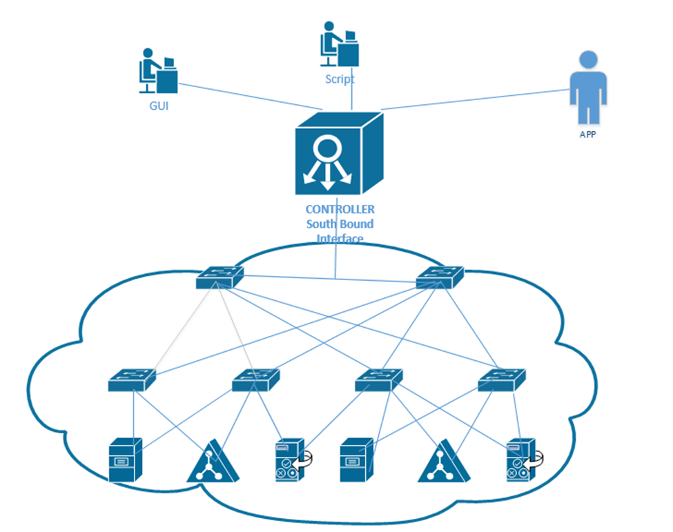
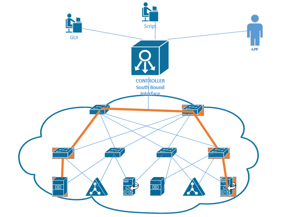
At the top of our network is our controller. We can connect to it via an App, a GUI, or a Script. The controller connects to the physical network through its Southbound Interface. We call the physical switch structure below the fabric. The fabric contains two components
- The overlay creates VLAN tunnels (called VXLAN tunnels) between different switches. The overlay allows us to move traffic from one end user device to another.
- The underlay connects each end user device with an IP address. The underlay helps us discover the different connected devices on the network.
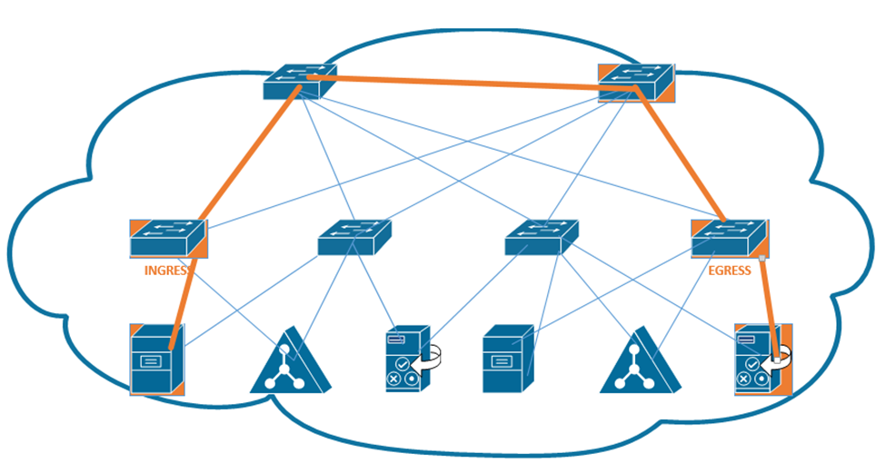
We create a VXLAN tunnel between each switch. The VXLAN tunnel allows end-user traffic to flow through the network. This is supported by the Cisco Virtual Extensible LAN protocol.
A VXLAN is a tunnel that allows end-user traffic to flow through the network. A computer on the left wants to talk to a computer on the right. The switches in the pathway create a VXLAN tunnel between the two devices and transport their traffic.
This tunnel is created by the overlay but supported by the physical underlay. We can use an existing network to build an underlay, and add configuration to each device to allow it to support an SDA. This is a cheaper option than purchasing all new devices.
We should make sure that our legacy hardware is compatible with SDA. We should verify that the network devices have compatible operating systems and hardware features for their roles. These roles include
- A Fabric Edge Node. This is a switch that connects to an end user device. It’s like an access switch.
- A Fabric Border Node. This is a switch that that connects to devices that don’t use the SDA. That could include devices like WAN routers.
- A Fabric Control Node. This is a switch or router that helps the control plane operate.
The question is – does your network have the hardware to support the new SDA network? You will need to check the specifications for each device.
If we can’t use the legacy equipment, we can build a new SDA network in parallel to the existing legacy network, and slowly migrate end user devices to the new network. This option is more expensive. More accurately, this option has a higher up-front cost. Eventually, all network hardware is replaced due to failure or age.
We should verify the following hardware features
- How many physical ports do we need and where?
- How fast does each interface need to be – Gigabit, 10 Gigabit, etc.?
- Do we need PoE?
- How much power do we need overall?
- What kind of cabling is installed – cat5e, cat6, multi-mode fiber, single-mode fiber?
- How much overall traffic will the network need to support?
When we connect physical switches in an SDA network, we don’t need to worry about EtherChannels or HSRP. We can use something called a routed access layer design. By default, all LAN switches in an SDA are Layer 3 switches. Cisco DNA will configure the devices to support the routed access layer by default. Any link between two switches is a Layer 3 link. The switches use the IS-IS routing protocol instead of STP or RSTP.
Access switches are located on the edges of the network. Each access switch becomes the default gateway for any end user device that is connected to it.
How does a device on an SDA communicate?
- It encapsulates the data in in a frame
- It sends the frame over the fabric (network) and sends it to the Access Switch.
- The Access Switch encapsulates the data inside a VXLAN header and sends it to the destination switch. The other switches in the network forward this frame based on the contents of its header.
- The exit switch (also an access switch) removes the VXLAN header and sends the frame to the end user device (known as an endpoint).
- The switch uses its ASIC to process the VXLAN header; therefore, an SDA doesn’t slow down any switches.
Why do we need an VXLAN? It allows us to encapsulate any type data inside a tunnel and deliver it to its destination. The VXLAN is flexible enough to support a range of header fields so that changes to the protocol can be implemented in the future, without having to make changes to the underlying hardware or software. At the same time, the VXLAN header can be supported by existing equipment.
A VXLAN encapsulates the entire frame, not just the IP packet because it must support Layer 2, not just Layer 3.
The first switch (known as the ingress switch) to receive a frame encapsulates it inside a VXLAN header and sends it through a tunnel to the egress switch.
Each switch has two IP addresses – an overlay IP address that uses the same subnet as the end user devices, and an underlay that uses a different subnet. Why? We need to build an underlay subnet that allows the controller to communicate with the switches. We also need an overlay subnet to transport end user data.
In the diagram below, each switch has two IP addresses. One IP address is an overlay IP address in the 10.10.1.0/24 subnet, which transports end user data. The second IP address is an underlay IP address in the 172.172.172.0/24 subnet.
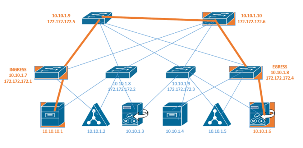
The overlay establishes a pathway in the fabric between two edge nodes. It uses the same IP address space as the endpoints. For example, the Ingress switch sends the end user data to 10.10.1.8.
Remember that a switch uses layer two to learn device MAC addresses from their frames, and that a router uses layer three to learn about neighboring routers through a discovery protocol. We call this the control plane.
Well, access switches (also known as edge nodes) can do the same thing as routers and switches. They can learn about connected endpoints through their MAC addresses, IP addresses, and subnets. Each connected endpoint is given unique ID called the endpoint identifier, or EID.
In our setup we also have a LISP, or Location ID Separation Protocol map server. Each fabric edge node tells the LISP map server about the endpoints that it has identified, and thus its ability to reach them. The server stores this information into a database. Now the server can create a routing locator or RLOC for each device.
That means that the server can identify a pathway to each endpoint. When the fabric needs to send a message to a specific device, it asks the LISP server for the appropriate destination. The LISP server checks its database.
The LISP server holds a database that shows each RLOC and corresponding EID. This database contains the underlay IP address of the edge node and the overlay IP address of the edge node.
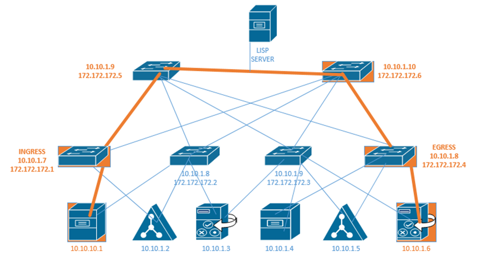
The Ingress Tunnel Router (ITR) receives frames from outside the fabric. It must decide on a tunnel to send the frame to. When it doesn’t know where to forward the frame, the ingress node contacts the LISP server and asks it how to reach the destination. If the LISP server has a destination in its database, it checks the IP address. It calls the egress router in the database and asks it if is still the correct router for that endpoint. The egress router verifies that it is still correct. Now the original ingress can encapsulate the frame with the destination.
In the above example, the LISP server knows that 172.172.172.1 can reach 10.10.10.1 and it knows that 172.172.172.4 knows how to reach 10.10.1.6. If 10.10.10.1 wants to send a message to 10.10.1.6, first the ingress router 172.172.172.1 asks the LISP server if it knows how to reach 10.10.1.6. The LISP server verifies that it does know how to reach 10.10.1.6. It contacts the egress router 172.172.172.4 and asks it if it is still a valid router for 10.10.1.6. If the egress router says yes, then the LISP server tells the ingress router to send its message to 172.172.172.4. The ingress and egress routers establish a VXLAN tunnel to forward their traffic.
The destination in the VXLAN header contains the IP address of the RLOC (172.172.172.4), but the destination of the IP packet contains the IP address of the actual end user device (10.10.1.6).