
4.1 Implement secure design principles in network architectures
- Open System Interconnection (OSI) and Transmission Control Protocol/Internet Protocol (TCP/IP) models
- Internet Protocol (IP) networking (IPSec, IPv4, IPv6)
- Secure protocols
- Implications of multilayer protocols
- Converged protocols (Fiber Channel Over Ethernet (FCoE), Internet Small Computer Systems Interface (iSCSI), Voice over Internet Protocol (VoIP))
- Micro-segmentation (Software Defined Network (SDN), Virtual eXtensible Local Area Network (VXLAN), Encapsulation, Software-Defined Wide Area Network (SD-WAN))
- Wireless networks (Li-Fi, Wi-Fi, Zigbee, Satellite)
- Cellular networks (4G, 5G)
- Content Distribution Networks (CDN)
There is a lot of information in the next two chapters about how networks work. I decided to provide more information so that people who do not have a background in networking can also understand.
The question we want to ask is: how does data on a network (or on the Internet) get from one point to another? How is it that when you plug a computer into an ethernet jack or connect to the Wi-Fi in a building, things just work (usually)? How do devices understand each other?
Well, manufacturers create devices according to established standards. Devices communicate with each other based on specific protocols (languages) that are defined by the international community. If you get into the business of making ethernet adapters, patch panels, fiber optic cables, switches, routers, etc., you will also have to follow those standards and protocols so that your devices can communicate with all the existing devices.
To create these standards and protocols, we had to create a model of the network. The OSI (Open Systems Interconnection) model is the single most important concept you will need to know (to pass the exam). OSI is just a concept.
There are seven layers:
- Layer 1 – Physical
- Layer 2 – Data Link
- Layer 3 – Network
- Layer 4 – Transport
- Layer 5 – Session
- Layer 6 – Presentation
- Layer 7 – Application
We are going to see some examples of communications that allows this model to make sense. But each layer carries data for the layers below it. Or in other words, each layer packages (encapsulates) the data from the layer below it. So, a device or program on the Application layer creates content and addresses it to a device on the Application layer at the other side. It gives this content to a device Presentation layer, which packages it, addresses it to the device in the Presentation layer on the other side, and sends it a device on the Session layer. This goes on until we get to the Physical layer.
When the data is received by the Physical layer on the other side, it is unpackaged and sent up the devices on each layer until it is received by the Application layer.
We need to understand the layers so that
- We can design a network and make sure that all the devices are connected and that they can communicate with each other properly
- We can identify which layer is affected when something goes wrong. This way, we can properly troubleshoot the software or configuration that is causing the issue
- We can start troubleshooting at the bottom layer and work our way up, or start at the top layer and work our way down, or figure out what is the highest layer that is working and then troubleshoot the next layer above it
Let’s look at an example. You want to send an e-mail. The Layer 7, Application Layer is the software that a user sees (Microsoft Word, Google Chrome, etc.). You type up the e-mail in Microsoft Outlook and send it off. But what is really happening? You only saw the seventh layer.
Well, Layer 6 is the Presentation Layer. It takes the data from Layer 7 and makes sure that the Application layer of the recipient can understand it. What if the recipient’s computer has a Mac or Unix operating system? What if the user doesn’t use HTML to display e-mails? What if the user’s computer is in a different language?
Idea: If you type up a document in Microsoft Word and then open it in Notepad, it will look like gibberish. Why? Because Microsoft Word has its own internal language that keeps track of things like fonts, formatting, layout, highlights, etc.. This language is useless to humans. Humans just want to see the properly formatted Word document or e-mail. So, the Presentation layer takes this gibberish that the computer understands and converts it into something that a human understands. If you open the same e-mail on your phone, or tablet, or 24” monitor, it will look different. The Presentation Layer on each device understands the capabilities of that device and translates the gibberish into a format that is suitable for its Application layer.
Layer 5 is the Session Layer. What is a Session? A Session is when two devices agree to communicate with each other for a period. When you send the e-mail, your computer calls up the receiving computer and says, “hey, I want to send you an e-mail”. The two computers use the session to exchange data and keep it open until one or both decide to close it. Technically (as we will find out layer), your computer wouldn’t directly contact the recipient’s computer. It would call up the e-mail server of its own service provider and send the e-mail there. That e-mail server would call the e-mail server of the recipient and send the e-mail there. The receiving e-mail server would call up the recipient’s device and further transport the e-mail. We just tried to make it simple for this example.
Layer 4 is the Transport Layer. Layer 4 takes the data from the Session Layer and packages it or breaks it into pieces. So, it might cut up your e-mail into chunks, give each one a number, and send each chunk separately to the recipient. The recipient has already agreed to receive these chunks because it has an established session. The Transport Layer on the other side would put them back together in the correct order. If some of those chunks don’t show up, the sending Transport Layer can send them again. The Transport Layer also puts the IP address of the recipient on each chunk. Later, we are going to look more specifically at a transport protocol known as TCP/IP.
Layer 3 is the Network Layer. Say you are in New York City and you are sending an e-mail to a device in Los Angeles. Layer 4 put the IP address of the recipient on each “chunk”. How does the data get to the destination? Throughout the internet are many routers and many cables. So, there are many pathways for data to get from NYC to LA. The router in your office looks at the destination IP address and decides about the next router to send the e-mail to (probably the main NYC router for your ISP). That router receives the data and makes its own decision sending it to a router in California. A main router in California sends the data to a router in LA. Finally, a router in LA forwards that e-mail to the recipient’s office router. Routers have algorithms that make these decisions efficient (as we will learn about later).
In the Layer 3, we call each “chunk” of data a packet. We will find out later that a packet has a very specific format so that routers can understand them. The size of the packet is known as the Maximum Transmission Unit. The sender and recipient agree on the largest size of packet that they can handle.
You can think of this layer like the mail. If you send a letter from NYC to LA, a mailman isn’t going to pick up the letter and drive straight to LA with it. Instead, that letter will go to the local NYC post office no matter the destination (just like your local office router must process all of the outgoing data no matter the destination). The local post office sorts mail going to California and ships them off to a main post office in California. That post office sorts the mail going to LA and ships them to the main LA post office. The main LA post office sorts the mail into routes for trucks and letter carriers, and those trucks and letter carriers deliver your letter to the recipient.
Layer 2 is the Data Link Layer. Layer 2 allows two directly devices to communicate. Every network device has a unique address called a MAC address. This address is burned in to the device from the factory and is unique regardless of the manufacturer. Layer 2 uses MAC addresses to forward traffic.
Remember those chunks called packets? Well, your computer doesn’t send packets. It creates the packet and puts the destination IP address on it, but your computer doesn’t know how to get it to California. So, the destination IP address is kind of useless to your computer.
Instead, your computer thinks about the next destination of the packet. It might be the same office, an office across the street, or an office in another country. As we will find out later, your computer just needs to think about whether the destination is within the office or outside the office (or in other words, whether it is behind the router or past the router).
Your computer finds out the MAC address of the packet’s destination. Then the computer packages this packet into a frame and adds the destination MAC address. If the destination is within your office, your computer puts the destination MAC address of the actual recipient. If the destination is somewhere else, your computer won’t be able to figure out the destination MAC address, so it puts the destination MAC address of the router as the recipient. The router receives this frame and removes the packet. Then it figures out the MAC address of the next destination (probably the next router). It puts the packet into a new frame with a new MAC address as the destination.
Your computer might be connected directly to your office router, but most likely it will connect to a switch. The switch understands and forwards frames based on the MAC address. We will find out more about how switches work later. When you send a frame to a device within your office, the switch can deliver that frame without having to talk to the router. When you send a frame addressed to the router (i.e. a frame containing a packet that has a destination outside of your office), the switch delivers that frame to the router.
In the case of our e-mail example, your computer encapsulates the packets containing pieces of your e-mail into frames. It puts the MAC address of your office router as the destination. The office switch delivers those frames to the router. The router removes the packet from the frame. The router finds the MAC address of the next router and packages the packet into a new frame. It puts the MAC address of the next router into the destination field on the new frame and sends it along. This process continues until the frame is finally delivered to the destination.
Layer One is the Physical Layer. It is the actual transmission layer and contains the wiring. Layer One also deals with directly connected devices. When your computer tries to send data to the switch, your computer and the switch must agree on a speed. What if your computer or the switch can’t handle a speed that is too high? Thus, two directly connected devices must agree on the speed to use on the line. If the line supports only a one-way transmission, they must also agree who will talk and who will listen at each time.
Now let’s think about the router in the receiving office. The Physical Layer receives the data (0’s and 1’s as an electronic or fiber transmission). That data is eventually recorded into a frame on Layer Two. The router’s Layer Two receives the frame. The router’s Layer Three technology removes the packet from the frame and figures out the destination MAC address of the device in the office that is entitled to it. It repackages the packet into a frame with the new destination MAC address and forwards the frame.
The switch in the office receives the frame and forwards it to the correct computer. The receiving computer removes the packet from the frame and sends it to the Transport Layer. The Transport Layer waits until all the associated packets are received and reassembles them. It also asks for missing packets to be resent (if any). The Transport Layer sends this assembled data to the Session Layer. The Session Layer sends the data to the Presentation Layer, which understands that the data is an e-mail. The Presentation Layer thinks about the best way to translate the content for the Application Layer. The Application Layer displays the e-mail in the recipient’s web browser or e-mail application.
When the router puts a packet into a frame, it is called encapsulation. When a router removes a packet from a frame, it is called deencapsulation. We are going to use those words more often throughout the book.
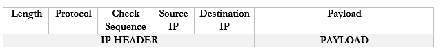
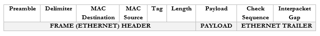
A frame has the following format
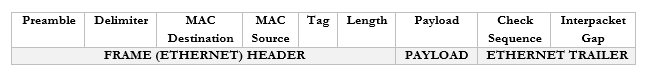
You don’t need to worry too much about these now but
- Preamble. This lets the devices know that this is an Ethernet frame. It is a bunch of 0’s and 1’s that let the two devices sync so that they don’t miss or misinterpret any of the following data and looks like this – 10101010 10101010 10101010 10101010 10101010 10101010 10101010 10101011.
- Delimiter. Basically, just a space to say “pay attention, the preamble is finished, and the real data is starting. We need the delimiter because the receiving device may have missed a portion of the preamble and won’t know how long until it ends.
- MAC Destination. The MAC address of the destination device.
- MAC Source. The MAC address of the source device.
- Tag. The tag is optional but tells us some information about the frame and its priority.
- Length. The length of the frame.
- Payload. The actual data we are sending.
- Check Sequence. A check digit that is mathematically computed from the frame data. It is used by the recipient to verify that the data was received correctly.
- Interpacket Gap. A space we make before sending the next frame.
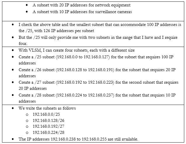
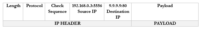
Remember that the router strips the headers from the frame to look at just the Payload. It can add new headers if necessary. Well, the Payload is actually a Packet with its own Header and Payload.
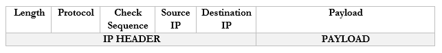
Notice that in the IP world, we only have headers and no trailer.
You don’t need to worry too much about these now but
- Length. The length of the packet.
- Protocol. The protocol that the packet will use.
- Check Sequence. A check digit that is mathematically computed from the packet header data. It is used by the recipient to verify that the data was received correctly.
- Source IP. The IP address of the destination device.
- Destination IP. The IP address of the source device.
- Payload. The actual data we are sending.
There are actually many more fields in the header, but they are less important.
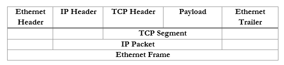
If we take the Payload from an IP packet, we can further dig inside it to find that it has its own header. This Payload is known as a Segment. If we were using TCP or UDP as our protocol for sending data, our Segment might look like this:

You don’t need to worry too much about these now but
- Source Port. The port that the data originated from.
- Destination Port. The protocol that the data is travelling to.
- Flag. A flag tells us whether the segment was sent to establish a connection or to acknowledge receipt of some other data.
- Payload. The actual data we are sending.
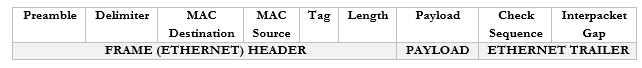
In summary, an ethernet frame looks like this
We can further summarize the contents and group them by OSI Layer.
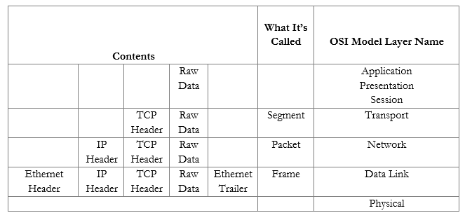
Now that we understand the model, we will revisit each topic in more depth.
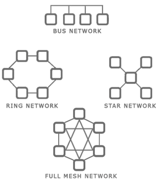
There are several types of network topologies
- Star – the star shaped network consists of a central hub and branches that connect to it. Most local ethernet networks are star-shaped. A central switch connects to multiple client devices such as computers and printers. A star network is also known as a hub-and-spoke.
- Ring – a ring network is one where each device connects to two neighbors, and no device is central. A ring network provides redundancy because the devices can continue to communicate even when one link fails. The ring network is common with large routers on the internet, which may have multiple routes.
- Bus – a bus network is where multiple devices share the same physical cable. Ethernet does not function with a bus network, but some forms of industrial communication do.
- Mesh – a mesh network is where each device has direct links to several other devices. A mesh network provides the most redundancy because the devices can continue to communicate even when multiple links have failed.
A mesh network is not possible with client devices such as computers and printers, because each typically has only one network interface. The mesh network exists for the backbone of the internet. - Hybrid – a hybrid network is a combination of the above types.
When you plan out your network, you should think about
- The size of your facility or campus
- The types of devices that you plan to connect
- The bandwidth that is required in each portion of your facility or campus
- The bandwidth that is required between portions of the facility or campus
- Whether fiber or copper connections are required
- The cost to acquire and maintain each network device
- The future needs of the organization and the expected growth
- The level of redundancy required
Some ideas
- The backbone of the internet is a mesh network in that every major ISP network is connected to several other ISP networks. This offers redundancy by providing multiple pathways for data transmission.
- A small office or home might have a star network where all the devices connect to a central modem/router.
- A larger office might have a star or hybrid star network with multiple layers. For example, a core switch in the main server room will feed smaller switches on each floor. Each client device will connect to one of these smaller switches.
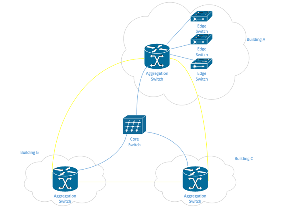
- A corporate or university campus with multiple buildings will have a star or hybrid star network. A core switch will be in the main server room and will feed a smaller aggregation switch at each building. Depending on the size of the building, it may have multiple edge switches, or devices may connect directly to the aggregation switch.
The campus may also have a fiber optic ring network that surrounds the entire campus. A ring provides additional redundancy. One benefit of the ring is that it can be constructed in the early stages of the campus. As more buildings are added, the ring can be cut and new buildings can be spliced onto it without having to install additional fibre.
In the following example, in yellow, we have a fiber optic backbone connected as a ring to the existing buildings – A, B, and C. We can add additional buildings onto the same backbone.
Each building has an aggregation switch that connects to the core switch. Building A has edge switches that connect to the aggregation switches. User devices in Building A can connect directly to each edge switch. User devices in Building B and C can connect directly to the aggregation switches.
We could draw the core switch as being on the backbone instead of being directly connected to each aggregation switch. If the fiber has enough capacity, we can directly connect the core switch to each aggregation switch without any issues.
Let’s look at some network types.
- Peer-to-Peer. You might recognize this from file sharing applications. Peer to Peer is a distributed architecture where every computer acts as a server to the other computers. A peer makes some of its resources available to the other peers without the use of an intermediate server.
Peer-to-Peer networks are used by file sharing applications, cryptocurrencies, Microsoft Windows update, and some other applications. In general, the devices on the P2P network do not have direct physical connections to one another and instead operate on top of another network. For example, you can set up a P2P network using devices on your office LAN. - Client-Server. A Client-Server network is one where multiple devices request content or communicate with a central server.
Examples of Client-Server networks include corporate file sharing, websites, and e-mail systems. For example, when you visit a website, that website is hosted on a server and your computer is the client. Multiple clients can connect to the same web server.
The Client-Server network also operates on top of another network such as a LAN or WAN. - Local Area Network (LAN). A LAN is the network in your office or home. It consists of devices connected behind a router (a router separates the LAN from the WAN).
- Wide Area Network (WAN). A WAN connects multiple networks together across long distances. It allows devices in multiple locations to act like they’re on the same network. An organization with offices spreads all over the country might connect them through a WAN. An internet service provider (or multiple ISPs) will own the backbone infrastructure that makes the WAN possible. Essentially, the company is paying the ISP a large amount of money to prioritize the traffic between its offices. If the ISP doesn’t own the entire backbone, then it negotiates with other ISPs to also prioritize the traffic in exchange for a portion of the fees.
WAN may also refer to standard internet connections such as DSL, Cable, Fiber, Broadband, etc. (i.e. connections that introduce your network to the outside world). - Wireless Wide Area Network (WWAN). A WWAN is a WAN but delivered over a cellular modem. WWANs are increasingly popular as back up connections and also for remote sites where the cost of extending a fiber optic cable would be prohibitive.
- Software-Defined Wide Area Network (SD-WAN). An SD-WAN is new technology that allows a company to connect multiple offices without the expense of a traditional WAN. It does so by connecting standard internet connections to an SD-WAN router at each office.
The SD-WAN router uses the internet connections to connect to cloud service providers and route traffic just as a traditional WAN would do. Since cloud service providers have data centers throughout most of the world now, and own the backbone infrastructure between those centers, the only slow portion of the SD-WAN will be between the office and the cloud. The result is the performance that is similar to a standard WAN without the cost. - Metropolitan Area Network (MAN). A MAN is larger than a LAN and can link multiple LANs together in a geographic area like a city. An organization with multiple offices in the same city might use a MAN.
- Wireless Local Area Network (WLAN). A WLAN is a portion of the LAN that is wireless. When wireless access points are connected to the LAN, they connect wireless clients with the rest of the LAN.
- Personal Area Network (PAN). A PAN is a small network formed by a user and his devices (such as a cell phone, tablet, and laptop). PANs are typically wireless and may use technologies like Bluetooth.
- Campus Area Network (CAN). A CAN is a network at a campus like a university or hospital. It may connect multiple LANs together. A CAN might be considered a LAN if no routers are involved. A CAN is different from a WAN in that the campus owns the infrastructure between the LANs.
- Storage Area Network (SAN). A SAN is a network that connects storage appliances to servers. A storage appliance is a type of hardware that is dedicated to storing large amounts of data. SANs could use ethernet or Fiber Channel.
- Multiprotocol Label Switching (MPLS). MPLS is an ISP technology that allows data packets to be routed from point to point across any type of transport medium (copper, fiber, or antenna), and via any protocol.
An ethernet packet is transported from the customer site to the ISP over the MPLS. The ISP uses ethernet (its own internal LAN) to transport the packet to its destination. From there, it exits and uses the MPLS to get to the destination customer site. - Multipoint Generic Routing Encapsulation (mGRE). mGRE was developed by Cisco. It allows a company with multiple sites to establish a VPN connection between them. A VPN allows a company to establish a “tunnel” between two or more sites. The traffic between the two sites is packaged and encapsulated over the tunnel. A VPN allows the sites to act like they are on the same network.
A VPN has poor performance compared to a WAN, but is less expensive, and can be established over standard internet connections.
Normally, a VPN must be manually configured on the router at each customer site. When the customer sites have public IP addresses that change, the routers must be manually reconfigured each time that the IP address changes.
When there are many VPN sites, the VPN is created as a “hub and spoke”, so that there is a central VPN server that connects to many branch offices. This way, each branch is not attempting to establish dozens of connections with other offices (which would overload the routers). But a large number of VPN connections can overload the VPN server as well.
mGRE allows the VPN tunnels to be created dynamically as required using Next Hop Resolution Protocol (NHRP). When the addresses of the spoke sites change, mGRE can use NHRP to find the new ones. Effectively, when a spoke site realizes that its IP address has changed, it calls up the hub and lets it know.
How does internet get into your building?
In legal terms, the Demarcation Point is where the ISPs equipment stops, and the customer’s equipment starts. It may also be known as the demarc, DMARC, MPOE, main point of entry, MPOP, or minimum point of presence. It might also be called the Service-Related Entry Point.
The customer may own some or all the customer premises equipment (CPE) or the ISP may own some or all of it.
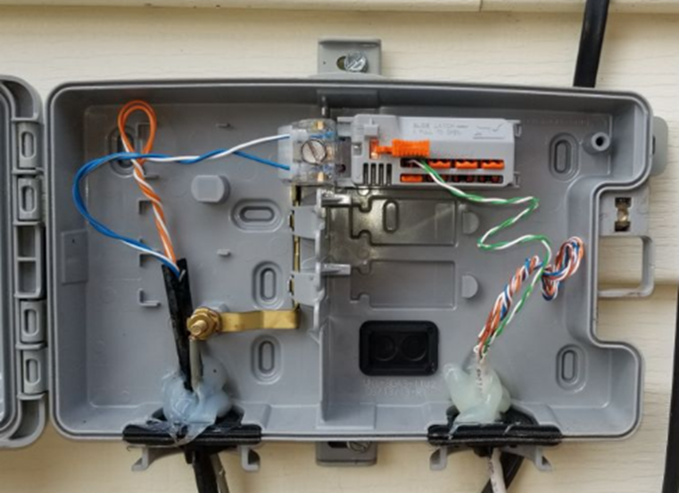
A demarcation point may be a termination block (such as a 66-block or 110-block), where wiring from the ISP is terminated. Or it may consist of a NID (Network Interface Device) such as the one below. Note that this NID has two sides – an ISP side and a customer side. The NID is usually installed outside a house or building. In a large office building or shopping mall, the demarcation point may be a large room with thousands of pairs of wiring.
What if the customer’s equipment is too far from the demarcation point? The ISP must then supply a demarcation extension. This is also known as a Service Interface Extension or inside wiring. The customer must typically pay for the cost of the extension.
An ISP may install a CSU/DSU (channel service unit/data service unit) at the demarcation point. The CSU/DSU converts the customer’s digital signal into an analog signal that travels over the telephone network.
Another device is called a Smart Jack. Where did the Smart Jack come from? In the past, to reduce competition, ISPs supplied and owned all the Customer Premises Equipment. ISPs used proprietary protocols to prevent customers from connecting their own CPE (such as modems). Eventually, the US federal government made it illegal and required each ISP to provide the customer with a physical wire connection, known as an RJ48. The problem was that the ISPs preferred to install their own equipment so that it could run diagnostic tests on the circuit. What if the customer complained that the internet wasn’t working? If the ISP owned the equipment, it could connect to it and perform diagnostic tests. If the customer owned the equipment, it couldn’t.
The solution was to create a Smart Jack. The smart jack is an electronic device with an RJ48 handoff that the customer could connect to. On the ISP side of the smart jack, they can monitor the connection and perform diagnostic tests. On the customer side, there is a standard RJ48 customer connection that satisfies the requirement of the federal government.
The ideas behind the network delivery (especially the LAN) have been expanded to virtualization technologies. Virtualization allows us to create multiple “virtual” servers on a single physical server. But when we try to connect those multiple servers to each other or to the physical network, we must employ network virtualization. This is related to Software Defined Networking (SDN). We will explore this topic in more details later.
But we have four ideas
- Hypervisor. The Hypervisor is a software application that runs as the base operating system on a physical server. It allows the user to create multiple virtual servers, which run inside the hypervisor. The hypervisor tricks the virtual servers into believing that each of them has separate physical hardware.
The advantage of a virtual machine is that we can maximize the resources of our hardware. We can run multiple servers on the same physical hardware instead of having separate servers for each application.
We can also run the same virtual server across multiple physical servers. This provides redundancy in case one of the physical servers were to experience a hardware failure. It also allows us to increase the resources of a high-demand virtual server so that it can have the computing power of multiple physical servers. - vSwitch. The vSwitch is a virtual switch that runs inside the Hypervisor and connects the multiple virtual servers. There can be multiple vSwitches if required.
- Virtual Network Interface Card (vNIC). Each virtual server can have one or more vNICs that allow the server to connect to the switch.
- Network Function Virtualization (NFV). NFV takes this a step further and virtualizes load balancers, routers, and firewalls, which used to require dedicated hardware.
Consider in a network that each function must be performed by a proprietary device, such as a load balancer, a firewall, a router, etc. For example, you may have a Cisco router or Cisco firewall. Now, what if we want to increase the capacity of the physical router? We would have to buy a larger router. What if we want to install a physical router in a cloud infrastructure, or inside a virtual machine? It is not possible.
With NFV, we can take the software component of the proprietary router, firewall, or load balancer and install it on a server (inside a hypervisor) virtual machine. The manufacturer of the proprietary hardware will create an “image” of the operating system on their router/firewall/load balancer, which we would then install as a separate virtual machine and virtually connect it to the other components. The virtualized infrastructure would run on generic physical hardware, which can be scaled up or down as required. It also requires less space in some cases.
Remember that the physical hardware must still physically connect to the internet, so there will always be a need for some physical infrastructure.
When I buy an internet connection, how is it delivered?
ISDN or Integrated Services Digital Network was an older type of internet connection. It delivered data, voice, video, or fax over the same physical telephone line. ISDN supported connection speeds of up to 128 kbit/s. At least two simultaneous connections were possible over a single ISDN line. ISDN was a circuit-switched network (between the user and the ISP) that provided subscribers with access to a packet-switched network.
ISDN technology was later used to develop the PRI, or Primary Rate Interface. PRI is a technology that can transmit multiple analog phone lines over a single pair of wires. Previously, each phone line required a separate pair of wires. The PRI delivers 23 “channels” of voice traffic and one overhead channel. That is, a PRI can handle up to 23 simultaneous phone calls on a single pair of wires. A phone call coming in over a PRI is tagged with the number that was dialed. This way, an organization could have hundreds of phone numbers on a single PRI, if they do not have more than 23 simultaneous phone calls.
A PRI is delivered over a T1 line, or Transmission System 1 line. The total bandwidth carried by a T1 is 1.544 Mbit/s. Each channel is 64 kbit/s. The different channels are separated with a time-division multiplexing algorithm. In other words, each channel receives a separate time slot for when its data is transmitted.
Who decided that T1 should be 1.544 Mbit/s as opposed to some other number? AT&T did. They invented T1 in the 1960s because they were trying to send telephone traffic long distances without the use of expensive equipment.
I need to go off on a tangent. Think of water flowing from a garden hose. It is continuous. It never stops. I could measure the flow rate every 10 seconds, or every second, or every 1/10th of a second, or every 1/100th of a second, etc.. This is known as my “sample rate”. What if the flow rate is 1 gallon/second at my first measurement and 1.1 gallons/second at my second measurement? Did it instantly jump from 1 gallon/s to 1.1 gallons/s? No. Between measurements it might have been 1.01, 1.02, 1.03 g/s, etc.. The point is, we can’t take an infinite amount of measurements. It’s physically impossible.
When you’re talking on the phone, the phone isn’t listening to you all the time. It’s taking samples of your voice and sending them to the network. If the samples are taken at short enough time intervals, the call can be reconstructed on the other side without any noticeable loss of quality. Our brains fill in the blanks.
A phone measures your voice 8000 times per second (8000 Hz). Each measurement is 8 bits in size. If I have 24 channels, then I need 8 bits x 24 channels = 192 bits/measurement. I must add one extra bit called the “framing” bit, which is used in error handling. So, I have 193 bits per measurement. Since there are 8000 measurements per second, 193 x 8000 = 1544000 bits/s or 1.544 Mbit/s.
Why did they choose 24 channels and not some other number? Rumor has it that AT&T performed some tests on cables they had installed underground in Chicago. They increased the transmission rate until the quality was just barely unacceptable. They had to stop at 24 channels.
Eventually other phone companies figured out a way to increase the bandwidth on a wire, and other T’s were developed. Another common T system is T3, which carries 44.736 Mbit/s.
Another system competing with the T1 is the E1, which carries up to 32 channels, for a total of 2.048 Mbit/s. Only 30 channels are useful, because E1 uses one channel for synchronization, and one for management. The E1 system uses time-division multiplexing just like the T1 system.
Other phone companies found ways to increase the bandwidth of the E1 system, resulting in the E2 (8 Mbit/s), E3 (34 Mbit/s), and E4 (140 Mbit/s) systems.
What if we need to transmit data long distances, and the copper wiring just won’t cut it? That’s where fiber comes in. Across large ISPs, Optical Carrier transmission rates have become standardized. The standard transmission rate is OC-1, which carries 51.84 Mbit/s. We can measure the transmission rate of a line in multiples of the standard rate. We can give this line a name in the format of OC-#, where # is the multiple. For example, if a line has a transmission rate of 103.88 Mbit/s, that is double the standard rate. We would call this line an OC-2 line.
Three common OC lines are the OC-3, which has a rate of 155.52 Mbit/s, OC-48, which has a rate of 2488.32 Mbit/s, and the OC-192 line, which has a rate of 9953.28 Mbit/s. The OC-48 line is used by many ISPs. OC-192 can work with 10 Gigabit Ethernet. Some undersea fiber optic cables use transmission rates of OC-768 (approximately 39 Gbit/s).
OC uses a system called SONNET, or synchronous optical networking protocol. Remember that data is broken up into packets, and that each packet has a header. The difference between a SONNET transmission and other types of transmissions is that the packet and header are sent at the same time. The header is mixed up with the rest of the packet.
In a smaller organization, the type of internet connection delivered may be DSL, Metropolitan Ethernet, Cable Broadband, or even Dial-Up.
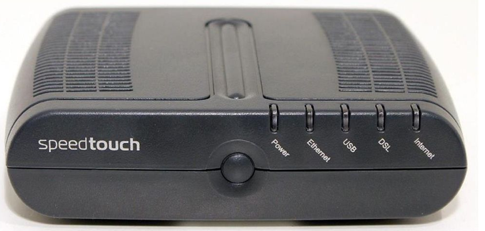
DSL or Digital Subscriber Line is delivered over a phone line. It may provide speeds of up to 150 Mbit/s. A subscriber will require a DSL modem to convert the signal from a phone line to an ethernet cable. The same phone line can be used to transmit voice simultaneously. Internet traffic is transmitted at a different frequency from voice traffic. At the ISP’s network, these are filtered and sent to different types of equipment. Voice traffic is routed to a telephone switch, while data traffic travels to an internet router. The device that performs this filtering is called a digital subscriber line access multiplexer or DSLAM. Each DSL modem must synchronize with the DLSAM so that they can filter out noise and errors. A DSL modem will typically have a “link” or “DSL” light that shows its synchronization status. Below is a photo of a common DSL modem.
Cable Broadband is a product competing with the DSL. While DSL is typically provided by a phone company Cable Broadband is provided by a cable television provider and is delivered over a coaxial cable. A subscriber requires a cable modem to connect to the network. At the provider’s facility, a device known as a cable modem termination system is installed. This device synchronizes with the subscriber cable modems and transfers their data to the internet.
It’s called broadband because multiple signals travel over a single wire at the same time, each occupying a different frequency. This is compared with other types of connections, which are known as baseband. On a baseband connection, a single signal travels over the wire.
The slowest form of internet is Dial-Up, but Dial-Up is generally available anywhere a phone line is. A Dial-Up modem converts an analog phone signal to and from a digital internet signal. The modem first calls a number dedicated by the ISP. The modem and ISP’s equipment synchronize and then transmit/receives data. An ISP does not require additional special equipment to maintain a Dial-Up service. A Dial-Up connection works at speeds of up 56 Kbit/s.
Many of these technologies are being replaced by Metropolitan Ethernet, also known as metro Ethernet, Ethernet MAN, or metropolitan-area Ethernet. How does it work? An ISP builds a large ethernet network in a city (or in a downtown area) and allows subscribers to connect to it. Why use metro Ethernet? It’s cheaper to maintain an ethernet network because it does not require special equipment at the subscriber’s side (modems) or at the ISP’s side (multiplexers and termination systems). The ISP already owns all of the backbone cables in the city.
The ISP may connect to the customer site via a router or switch. Traffic from different customer sites is aggregated with larger switches. Multiple MANs can be aggregated via an IP-MPLS system.
An ISP may provide MPLS over its metro ethernet. An ethernet packet is transported over MPLS from the customer to the ISP. The ISP uses ethernet to transport the packet to its destination. Why use MPLS? The ISP can handle traffic from any type of medium or protocol. It is easy to perform end-to-end troubleshooting of an MPLS network than a pure ethernet network.
A new alternative to metro Ethernet is metro optical (although nobody calls it this). It is basically metro Ethernet delivered over a fiber optic cable.
A leased line is a dedicated circuit between two offices. It is permanently connected. It may also be called an Ethernet leased line. A company that wants to connect two offices with the same LAN can rent a leased line from an ISP (subject to availability). The leased line may have an unlimited bandwidth or be limited to a specific speed.
In rural areas, internet may be delivered over a satellite modem. Satellite has a high latency and is expensive, but in some areas, it is the only choice.
An internet connection can be transported via Copper, Fiber, Satellite, or Point-to-Point antenna.
Copper is the oldest transmission medium. Traditionally, the phone and cable companies owned copper cable for transmitting phone calls and cable television. They later began using them for transmitting internet. DSL, Dial-Up, cable, T1, E1, T3, and E3 are transmitted over copper.
Fiber is quickly replacing copper, even in residential neighborhoods. Most fiber is being installed by the phone companies, which own the right to install additional wiring. Cable companies and cellular providers own some fiber as well. Metro Ethernet is typically delivered over fiber, although it could be delivered over copper.
A satellite internet connection is suitable for rural areas that have no physical wiring. The biggest problem with satellite internet is that it has high latency. It takes a long time for a signal to travel from a subscriber’s satellite dish to a satellite in the earth’s orbit (up to 120 ms). The total latency can be up to 1000 ms, whereas the latency of a broadband connection may be only 40 ms. A subscriber must have a “line of sight” between their satellite antenna and the satellite in the sky. If it is blocked by trees or clouds, the signal will suffer.
A traditional satellite dish can only receive data. Since the internet is two ways, a satellite internet connection requires a transmitter that points back at the satellite in the sky. Sometimes, the satellite connection is combined with a dial-up connection. Data that requires low latency is transmitted over the dial up connection.
Satellite internet can also be transmitted over a portable modem. These transmit with a speed of about 500 kbit/s but cost up to $5 per megabyte of data transmitted.
A Point-to-Point antenna is another less common way to provide internet service without wiring. A service provider installs a transmitter at the top of a large tower in the center of a city. Each subscriber installs an antenna on their rooftop, pointed towards the tower. The internet is transmitted over a radio signal. The subscriber connects his antenna to network equipment (typically provided by the ISP), which then connects to his network.
How can you decide which internet connection you need? We will discuss this in more detail, but in general
- What bandwidth do you require? Think about the performance of the internet connection.
- How many offices do you have and where are they located? This will affect the types of internet connections available.
- Do you need to connect the offices together over a WAN or SD-WAN, or will a VPN be suitable?
- What is the budget and what is the cost of the different options?
- Do you need redundant connections? Consider some common scenarios
- A single office might have one broadband connection and one back up cellular connection.
- A business with multiple offices across many states/provinces will have a WAN (although many businesses are switching to SD-WAN). Rural offices connect back to the main offices over a VPN since the cost of a WAN in those areas may be too expensive.
- An office may route normal internet traffic over a broadband connection and inter-office traffic over a WAN. This allows them to purchase a lower-capacity WAN.
- Some remote offices may connect via satellite or cellular.
- A single office might have one broadband connection and one back up cellular connection.
Remember that each network device has a MAC address (assigned from the factory) and an IP address (assigned by the network)? We are going to learn where IP addresses come from and who regulates them.
An IP address has four sections, known as octets. For example, 192.168.0.4 is an IP address.
Each octet is a three-digit number separated by a period. The maximum value of an octet is 255 and the minimum value is 0. So, the range of IP addresses is from 0.0.0.0 to 255.255.255.255. How many IP addresses are there? 4,294,967,296. Are there enough IP addresses to go around if you consider that each person probably has a work computer, a home computer, a cell phone, and that there are many other servers and internet of things devices running in the background? Of course not.
A public IP address is one that is accessible from anywhere on the internet, and a private IP address is one that is only accessible from inside a local network. The devices on your local network (i.e. inside your home or office) probably have private IP addresses.
The router in your home or office probably has a public IP address assigned to the port that connects it with the outside world. The router probably also has a private IP address assigned to the port that connects it to the rest of your internal network.
Who decides what IP address you get? Your internet connection is assigned an IP address by your internet service provider. Your internet service provider is assigned a block of IP addresses by a larger organization (such as a larger ISP if they buy their internet from somebody else). At the top of the food chain is ARIN (American Registry for Internet Numbers).
ARIN assigns blocks of IP addresses to each ISP and to larger organizations. IPv4 addresses are scarce because there are more devices than IP addresses, and because in the early days of the internet, organizations were assigned large blocks of addresses. Nobody thought that the internet would grow to be as big as it is, so ARIN went crazy and gave everybody tons of IP addresses.
The US Department of Defense owns about 5% of the IPv4 addresses (addresses that start in 6, 7, 11, 21, 22, 26, 28, 29, 30, 33, 55, 214, and 215).
A few blocks of IP addresses have been reserved for private IP addresses and some blocks have been reserved for special functions as we will find out later.
The following IP address ranges are reserved for private use per RFC1918.
- 10.0.0.0 to 10.255.255.255
- 172.16.0.0 to 172.16.255.255
- 192.168.0.0 to 192.168.0.255
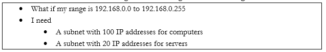
If you have an office or internal network, you can set up an internal addressing scheme by choosing one of the above three ranges. In my example office below, I chose the range 192.168.0.0 to 192.168.0.255. What range will you choose?
- 10.0.0.0 to 10.255.255.255 is the largest network, with a range of 16,581,375 possible addresses. This type of network is known as a class A network.
- 172.16.0.0 to 172.16.255.255 is the second largest network, with a range of 65,025 possible addresses. This type of network is known as a class B network.
- 192.168.0.0 to 192.168.0.255, is the smallest network, with a range of 256 addresses. This type of network is known as a class C network.
If we have a small network, we should choose a small range. Smaller network equipment (such as in a home or small business) might not be able to handle a larger range of IP addresses. As we will see later, we can subdivide a larger range into several smaller range, and assign each one to a different function.
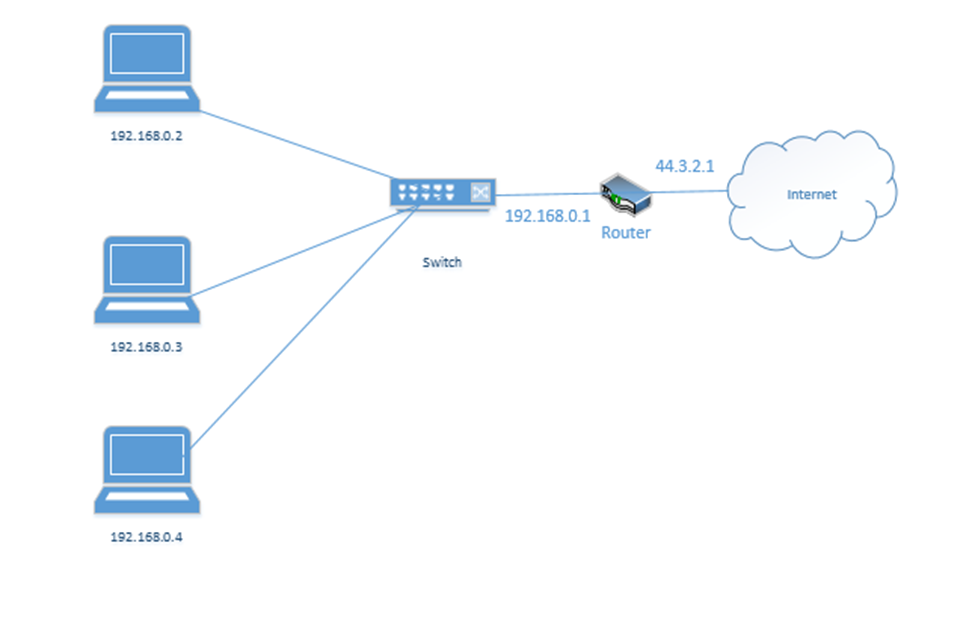
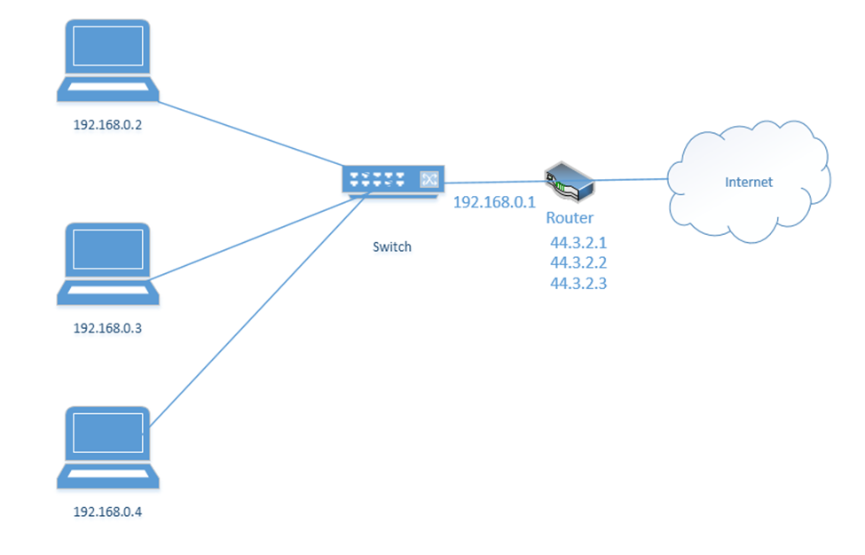
Let’s look at our example office. In our example, the ISP assigned us one public address: 44.3.2.1. Most of the IP address space is public. In theory, any device with a public IP can reach any other device with a public IP (unless a firewall blocks it). Thus, other devices on the internet can communicate with our network by contacting 44.3.2.1.
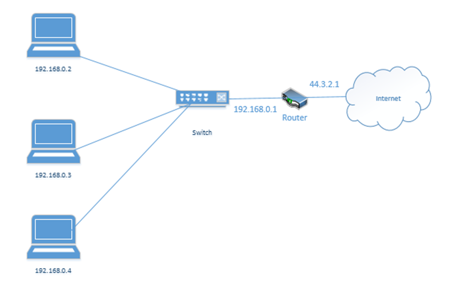
In my example office, there are three computers, with IP addresses of 192.168.0.2, 192.168.0.3, and 192.168.0.4. They connect to the switch. Notice that the router (which sits on the edge of the network) has a private IP address of 192.168.0.1 and a public IP address of 44.3.2.1. This allows the router to pass traffic between the private network and the public network. Devices within the private network can reach the router (and therefore the outside world) by contacting 192.168.0.1.
If our business was so large as to require multiple locations, we could choose the range 10.0.0.0 to 10.255.255.255 and then subdivide it further so that each location receives a block from our range. For example, one location receives the range 10.0.0.0 to 10.0.255.255, and the second location receives the range 10.1.0.0 to 10.1.255.255, etc.. It might look like the drawing below
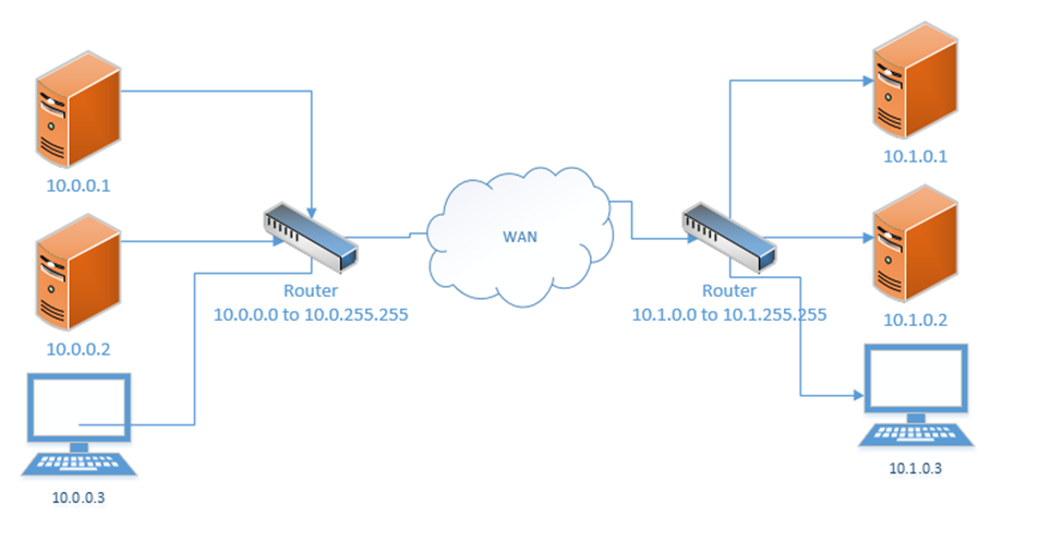
This would require us to implement a Wide Area Network or point-to-point VPN. The WAN allows us to configure the routers so that all the computers in all our offices think that they are on the same physical network.
Each local area network can use the same range of private IP addresses as any other network because a device on one LAN won’t talk directly with a device on another LAN. Instead, the pass their messages to their routers, which then deliver the traffic. As long as each router has a unique public IP address, we won’t encounter any issues.
So far, when we’ve been talking about IP addresses, we’ve actually been referring to IPv4 (version 4) IP addresses. But the world has been running out of IPv4 addresses, and so a new standard was created. This standard is known as IPv6.
In the IPv6 world, fc00::/7 is the only private range of IP addresses. It is better written as fc00:0000:0000:0000:0000:0000:0000:0000 to fdff:ffff:ffff:ffff:ffff:ffff:ffff:ffff.
How did I get from fc00::/7 to all of that gibberish? We’ll find out later. But the point is, the range is massive. There is no need for each private network to have the same address as any other private network.
If we mash two private IPv4 networks together, we will have some conflicts. We will find that two devices have the same IP address, and one of them won’t be able to communicate. But if we mash two private IPv6 networks together, we won’t have any conflicts because each private IPv6 address is randomly generated. In fact, if mashed all of the private IPv6 networks together, we probably won’t have any conflicts.
Loopback and Reserved
Some addresses are reserved. They can’t be assigned to anybody.
The addresses that are reserved
- 127.0.0.1 is called the loopback address (mapped to the hostname localhost). Every network device and computer consider 127.0.0.1 to belong to itself. If I send traffic from my computer to the address 127.0.0.1, it loops back and heads straight back to my computer.
What’s the point? Let’s say that my organization maintains two servers – a web server and a database server. The web server connects to the database server over the local network. If I decide to install the web server software and database software on the same physical machine, then I could reprogram the web server to look for the database server at the 127.0.0.1 address.
What if my server IP address is 192.168.0.1? Why do I need to specify 127.0.0.1? Why can’t I just tell the web server to look at 192.168.0.1? I could, but that would create unnecessary traffic along the network for a packet that doesn’t need to leave the server. Also, what happens if my server IP address changes frequently? I don’t want to reprogram the server every time the IP address changes. Or what if I don’t have an active network connection? What if I’m running a sensitive internal application but the application is looking for a network connection? I can specify 127.0.0.1.
127.0.0.1 is also used to test the internal operation of the network card. If I am troubleshooting a network connection, I might try to send traffic to 127.0.0.1. If it fails, I will know that the network problems are internal to the machine. - 0.0.0.0 to 0.255.255.255 is reserved for software testing.
- 169.254.0.0 to 169.254.255.255 is reserved for the link local IP addresses. This is a random IP address that a device assigns itself when it can’t find a DHCP server. That is, if a device joins a network and doesn’t have a preprogrammed IP address, and the network doesn’t assign it an IP address, it will randomly assign itself an IP address from that range.
- 255.255.255.255 is reserved for broadcasts. That is, when a device wants to send traffic (like an announcement) to all the other devices on its local network, it can send them to that address.
- There are other IP addresses that are reserved but to list them all would take forever.
On the IPv6 side
- ::1 also known as 0000:0000:0000:0000:0000:0000:0000:0001 is the loopback address
- fe80:0000:0000:0000:0000:0000:0000:0000 to febf:ffff:ffff:ffff:ffff:ffff:ffff:ffff is the link local address
- 2002:0000:0000:0000:0000:0000:0000:0000 to 2002:ffff:ffff:ffff:ffff:ffff:ffff:ffff was used by the 6to4 IP address conversion protocol. More on this later.
- ff00:0000:0000:0000:0000:0000:0000:0000 to ffff:ffff:ffff:ffff:ffff:ffff:ffff:ffff is the multicast address range. More on this later.
Default Gateway and Subnet Mask
Recall that we have public IP addresses and private IP addresses. When a device wants to send traffic to another device
- It first must ask itself: is this device on my local network or is it somewhere else?
- If it is local, the computer sends the traffic to the switch, but with the MAC address of the destination device in the header.
What happens when the destination is not local? Then the device must send the data to a router. But how does it know which router to send it to? And how does it know whether the destination device is local?

Every device has network settings, which include at least three items
- IP address – this is the IP address assigned to the device
- Subnet mask – this tells the device how big its local network is; the local network is known as a subnet
- Default gateway – this is another name for a router. In other words, the default gateway connects the local network with the outside world.
The device uses its IP address and the subnet to figure out the range of IP addresses in its local network. If the destination IP address is not in the local network, then it is sent to the default gateway.
This is going to be the hardest part of the book. Learning the complicated math about subnets.
A subnet mask looks like an IP address. It is 32-bits long (each octet is 8-bits. Remember that computers are electrical. They only think in terms of “on or off”. So, a 1 is on, and a 0 is off.
8-bits makes up one byte. A computer with 8-bits can only count to 255 in one operation. If I make a table that is base-two (every entry is double the previous entry), I can combine these eight numbers to make any number from 0 to 255. Below is my table.
| 128 | 64 | 32 | 16 | 8 | 4 | 2 | 1 |
If you look at the 8-bits in a byte, each bit is assigned to one of the numbers in my table. If the bit is a one, or in “on’ position, then the number is added to the total, and if the bit is a zero, or in the “off” position, then the bit is ignored.
For example, my byte is 11011001. If we write this byte into the base-two table below, and add up the corresponding values,
| 128 | 64 | 32 | 16 | 8 | 4 | 2 | 1 |
| 1 | 1 | 0 | 1 | 1 | 0 | 0 | 1 |
The value of this byte is 128 + 64 + 16 + 8 + 1 = 217
Thus, we have two ways to write out this number, either as 217 or as 11011001
At its most basic level, when a processor is doing math, it’s has an electrical circuit that’s turning these different bits on and off.
So what? There is a small microprocessor inside each network card and router that thinks about IP addresses. This allows those devices to make subnet mask and IP address calculations quickly.
255.255.255.252 is an example of a subnet mask.
We could write it out as
11111111.11111111.11111111.11111100 if we wanted to. We call this a binary number. How did I get this? I simply went back to my table:
| 128 | 64 | 32 | 16 | 8 | 4 | 2 | 1 |
What numbers to add together to come up with 255? Well, if I start at the left, and work my way to the right, I found that I need all of them.
| 128 | 64 | 32 | 16 | 8 | 4 | 2 | 1 |
| 1 | 1 | 1 | 1 | 1 | 1 | 1 | 1 |
When the computer wants to express the number 255 in binary, it must turn on all of the bits in the byte.
What about 252? To get to 252, the computer must turn on the first six bytes.
| 128 | 64 | 32 | 16 | 8 | 4 | 2 | 1 |
| 1 | 1 | 1 | 1 | 1 | 1 | 0 | 0 |
Now if we write out the binary value of each octet in the subnet mask, we get 11111111.11111111.11111111.11111100.
We could also call it a /30 subnet mask, because it has 30 “1’s” in it. Note that you’ll never see a subnet mask like 255.255.255.217. In a subnet mask, the 1’s always appear on the left and the 0’s always appear on the right.
| 128 | 64 | 32 | 16 | 8 | 4 | 2 | 1 |
| 1 | 1 | 0 | 1 | 0 | 1 | 1 | 1 |
In binary, 217 is written as 11010111. Thus the subnet mask 255.255.255.217 would be written as 11111111.11111111.11111111.11010111, which would put some 1’s to the right of some 0’s, which would be invalid.
Many network engineers like to reference a subnet mask as a “/30” or “/28” or “slash whatever number it is”, instead of saying the entire name.
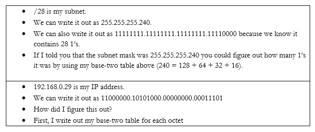
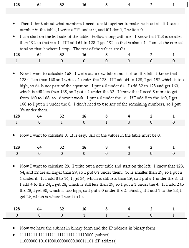
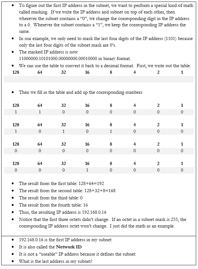
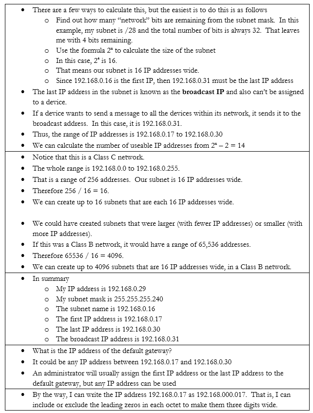
Let’s do an example. If my device IP address is 192.168.0.29 and my subnet mask is /28, how big is my network? What IP address does it start on and where does it end? We can figure it out.
In the IPv6 scheme, there is no such thing as a subnet mask. If there was, the math would be complicated. But we do have subnets. We also have sub-subnets and sub-sub-subnets.
Some things to note about IPv6 addresses
- An IPv6 address is 128 bits wide (unlike an IPv4 which is 32 bits wide).
- Each “octet” in the IPv6 address is 4 characters wide, but each octet is 16 bytes wide (unlike an IPv4 octet which is one byte wide)
- An octet can contain numbers from 0 to 9 and letters from a to f. This is called hexadecimal because each place goes up to 16 with the letters. If I was counting in decimal, I could count 1, 2, 3, 4, 5, 6, 7, 8, 9. When I get to 9, I must move to the next place (10). If I was counting in hexadecimal, I would count 1, 2, 3, 4, 5, 6, 7, 8, 9, a, b, c, d, e f. When I get to f, I must move to the next place (10). My hexadecimal 10 is misleading because it is actually worth 16.
- There are eight octets in an IPv6 address.
- Each octet is separated by a colon
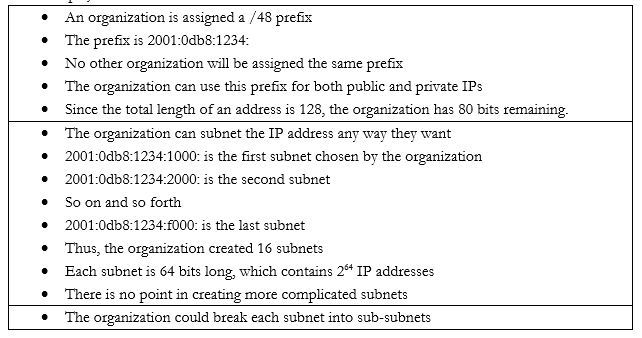
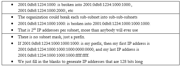
An IPv6 address has two parts. The first part is called the prefix. A /48 prefix is common.
For example,
Earlier I said that
- 10.0.0.0 to 10.255.255.255 is the largest network, with a range of 16,581,375 possible addresses. This type of network is known as a class A network.
- 172.16.0.0 to 172.16.255.255 is the second largest network, with a range of 65,025 possible addresses. This type of network is known as a class B network.
- 192.168.0.0 to 192.168.0.255, is the smallest network, with a range of 256 addresses. This type of network is known as a class C network.
The network classes applies to both public and private networks, not just the private ranges that I described above.
- A Class A network contains 224 addresses. Networks in the range of 1.0.0.0 to 126.0.0.0.0 are Class A networks. So, a network like 2.0.0.0 to 2.255.255.255 is a Class A network.
- A Class B network contains 216 addresses. Networks in the range of 128.0.0.0 to 191.0.0.0 are Class B networks. So, a network like 130.0.0.0 to 130.0.255.255 is a Class B network.
- A Class C network contains 28 addresses. Networks in the range of 192.168.0.0 to 223.0.0.0 are Class C networks. So, a network like 200.0.0.0 to 200.0.0.255 is a Class C network.
We have two more classes of networks
- Networks in the range of 224.0.0.0 to 239.0.0.0 are Class D networks.
- Networks in the range of 240.0.0.0 to 254.0.0.0 are Class E networks.
These networks do not have subnet masks. They are strictly experimental, and most routers will not accept traffic from IP addresses in their ranges. The use of a Class A, B, or C network is called Classful Subnetting.
The opposite is Classless Subnetting. How does it work?
If my network is 192.168.0.0 to 192.168.0.255, I have 256 IP addresses. I can break it down into one network of 256 addresses, or I can break it down into 2 networks of 128 addresses each, or 4 networks of 64 addresses each, or 8 networks of 32 addresses each, etc.. If my network was a Class A or Class B network, I could break it down into even more subnets and/or have even more IP addresses per subnet.
| Subnet Mask | Number of IPs per Subnet | Number of Subnets |
| /24 | 254 | 1 |
| /25 | 126 | 2 |
| /26 | 62 | 4 |
| /27 | 30 | 8 |
| /28 | 14 | 16 |
| /29 | 6 | 32 |
| /30 | 2 | 64 |
There is no /31 or /32 subnet because we need at least three IP addresses in a subnet – the network ID, the useable IP, and the broadcast IP. A /31 subnet would be two IP addresses wide and a /32 subnet would be one IP address wide.
We could choose to break down our network into subnets of any size based on our requirements. We might want to create separate logical networks for each class of devices. This allows us to improve security by preventing a device on one subnet from communicating with a device on another subnet. It also makes it easier to manage the network.
We ask ourselves what the largest required subnet is and go from there. This is known as Fixed Length Subnetting. Looking at the above table, we have a few choices for how we can break down our network into equally sized subnets.
What if I need subnets of different lengths? Introducing the Variable Length Subnet Mask
VSLM is part of a system called Classless Inter-Domain Routing, or CIDR. Writing the IP address with the subnet mask at the end as a slash is known as Classless Inter-Domain Routing Notation.
We can also write an IPv6 address in CIDR notation. Instead of writing the full IP address, we would write the IP address and subnet length. For example, we could write 2001:0db8:1234:0000:1111:2222:3333:4444 /48
Since we’re on the subject, let’s look at some other types of special IP addresses
- Broadcast. A broadcast is a message that is sent to all the devices in a single broadcast domain. That is, if my computer wants to send a message to all the other computers in the subnet, it addresses it to the broadcast IP address.
The broadcast IP address will be the largest IP address in a subnet. For example, if the range of IP addresses is 192.168.0.1 to 192.168.0.255, then the broadcast IP address will be 192.168.0.255.
On an IP network, this message is called a broadcast packet. Remember that a router will not forward a broadcast packet.
Looking back at the structure of our IP packet, we have a source and destination IP address. The destination will be the broadcast IP.
But the computer must send this packet to the switch that it is connected to, so it must put it inside a frame. A frame with a broadcast packet will be called a broadcast frame. The broadcast MAC address is FF:FF:FF:FF:FF:FF. Any frame addressed to this address will be forwarded to all devices in the broadcast domain.
The broadcast domain is all the network devices that will receive a broadcast. That is, all of the devices in a subnet make up a broadcast domain.
When the switch receives this broadcast frame, it will notice that the destination MAC address is FF:FF:FF:FF:FF:FF and send it to all of the connected devices.
IPv6 does not use broadcasts, only multicast.
You can think of a broadcast packet like some flyers you see in your mailbox. An advertiser will print a pile of them without any addresses and dump them at the post office. The mail man will stick one flyer in every mailbox on his route. The route is the broadcast domain, and the flyer is the broadcast packet.
- Multicast. Both IPv4 and IPv6 use multicast. A multicast message allows a sender to send a message to multiple recipients (but not all the members of a broadcast domain). The sender creates a single multicast packet, but routers and switches replicate that packet and send it to all the required destinations.
On a network, there can be multiple multicast “groups”. Each group has an address. A device that wishes to receive messages addressed to a group sends a “membership report” message to the group’s address, indicating its desire to receive the messages.
Multicast works through the Internet Group Management Protocol. The current version is IGMPv3, which allows a device to leave a group that it previously joined (previous versions only allowed a device to join and not leave).
Who keeps track of the group? The local network router keeps track of the groups and the subscribers. When the local router receives a packet addressed to the group, it sends it to all of the subscribers in the group.
You can think of a multicast packet like a newsletter. You must subscribe to the newsletter, but every person who subscribes receives a copy. You can unsubscribe if you want. - Unicast. A unicast packet is one that is addressed to a specific recipient. Most communications are unicast. When a device wants to send a packet via unicast, it puts the IP address of the recipient in the destination.
A unicast packet is like a letter from your friend. It has your address and is sent specifically to you. - Anycast. An anycast packet allows a computer to send a message to one of many recipients. Any anycast group contains more than one recipient. When the router receives a packet addressed to the anycast group, it chooses one recipient from the group and sends the packet to it. The chosen recipient is based on a routing algorithm. The algorithm may choose a recipient that is closest to the sender or use other factors.
Anycast is used in load balancing. For example, if I have multiple servers that perform the same task, I can assign all of them to the same anycast group. I can direct traffic to the anycast group’s address. The router can then decide which server receives each piece of traffic by selecting the closest server.
What happens when we have two networks separated by a router and they have different IP addressing schemes? The IP addresses aren’t compatible.
Consider the following example. I have a router with the address 44.3.2.1. That is the address that devices on the internet know it as. Behind the router is my internal network, which has three devices, each with a different address – 192.168.0.1, 192.168.0.2, and 192.168.0.3. Nobody on the internet knows anything about my internal network – they can only see my router.
Remember that addresses that start with 192.168 are known as private IP addresses. They can only be used on internal networks. 44.3.2.1 is an example of a public IP address. But how can a computer on an internal network talk with devices on the internet? And how can devices on the internet talk to a computer on an internal network?
We use a system called Network Address Translation, or NAT. NAT is a tool used by the router to move traffic between the internet and the local network devices. There are several ways that NAT can work depending on the number of public IP addresses available to the router and depending on the number of devices on the internal network.
Let’s say the router has three public IP addresses – 44.3.2.1, 44.3.2.2, and 44.3.2.3 – at least one public IP address for each private IP address. The router has two options for moving traffic between the internet and the internal network.
- It can create a Static NAT, also known as a one-to-one translation. The router says that 44.3.2.1 belongs to the device 192.168.0.2; 44.3.2.2 belongs to the device 192.168.0.3 and 44.3.2.3 belongs to the device 192.168.0.4.
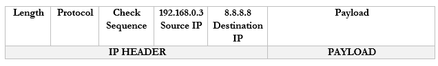
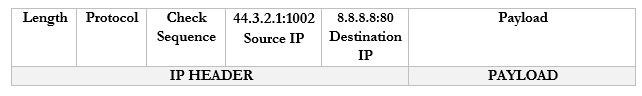
Let’s look at an example. 192.168.0.3 wants to send traffic to google.com (8.8.8.8).- The device creates a packet with a source field of 192.168.0.3, and a destination field of 8.8.8.8
- The device wraps the packet in an ethernet frame and sends it to the router (the frame’s destination MAC address is that of the router)
- The router strips the frame header and looks at the packet
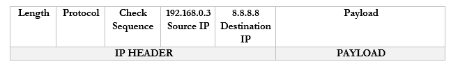
- The router changes the Source IP (192.168.0.3) of the packet to reflect its external address. It knows that it mapped 44.3.2.3 to the internal IP 192.168.0.3, so that is the IP address that it uses.
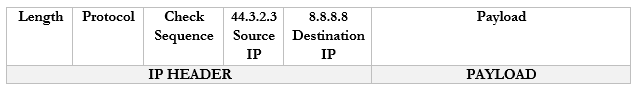
- The router sends the packet to the 8.8.8.8 address. It uses a routing protocol to send this packet, which we will worry about later.
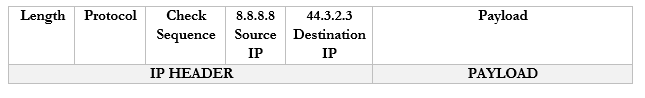
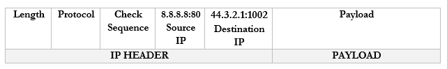
- The Google server at 8.8.8.8 receives the packet and sees that it came from 44.3.2.3
- The Google server replies to 44.3.2.3 by creating a packet with a Destination IP of 44.3.2.3
- The router receives this packet and checks the NAT mapping. It knows that 44.3.2.3 is mapped to 192.168.0.3
- It changes the Destination field in the packet to 192.168.0.3 and wraps it in a frame.
- It puts the MAC address of the computer in to field and sends it to the computer through the switch.
- One to One Translation is great but remember that IPv4 addresses are scarce. What if I have more internal devices than IP addresses (which is usually the case)? I might need to set up a Dynamic NAT.
Dynamic NAT works exactly like the Static NAT with one difference. That is, with a Dynamic NAT, the router maintains a “pool” of external IP addresses. Each time an internal device needs to access the internet, the router assigns it an external address from the pool. The router keeps track of the assignments in a table. It changes the addresses on the packets just like it did with the Static NAT.
As long as the device is accessing the internet, it continues to be assigned to the external IP address. If a device doesn’t access the internet for a while, then the NAT entry is deleted from the table and the IP address returns to the pool.
- But what if I have a massive number of internal devices and they all want to access the internet at the same time? What if I don’t have enough IP addresses to go around even with Dynamic NAT? I can use PAT or Port Address Translation.
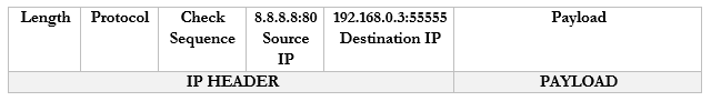
We haven’t talked about “ports” yet. But we are going to introduce a new idea. Look at the computers on the left. Each one has one IP address but it might have many different applications that connect to the internet – e-mail, Skype, Teams, Windows Update, web browser, etc.. If it is receiving traffic from multiple sources, how does it know which source should be directed to each application? Introducing ports. A port is a number that is attached to the end of the IP address. In this case, we aren’t talking about physical ports, but logical ports.
Things are going to get more complicated. The Google server way in California spends its whole day listening to incoming web traffic. It does so on port 80. That is, it understands that traffic sent to 8.8.8.8:80 is requesting the Google website. It might ignore other traffic, or it might listen for different types of traffic on other ports. For example, it might listen for management traffic on port 300.
Now, let’s say that I have 100 browser tabs open at the same time. I am trying to access Google, CNN, YouTube, etc.. If my computer is bombarded with traffic from all these sources at the same time, it will not know which packet goes where. So, what can it do? It adds a port to the end of each request.
For example, it sends a packet to Google.com with the port 55555 as the source. Google.com knows that it should send a reply back to 192.168.0.3:55555.
It sends a packet to CNN.com with the port 55556 as the source. CNN.com knows that it should send a reply back to 192.168.0.3:55556.
It sends a packet to YouTube.com with the port 55557 as the source. Google.com knows that it should send a reply back to 192.168.0.3:55557.
These port numbers were present in the NAT scheme. But the router didn’t change the port numbers. It didn’t have to because it only changed the IP address (there was a unique address for each internal device). Now there isn’t.
A router doesn’t really have different software applications. But it can still understand ports. Ports allow the router to expand the number of IP addresses.
Let’s look at our example. But now our router has only one external IP address: 44.3.2.1.
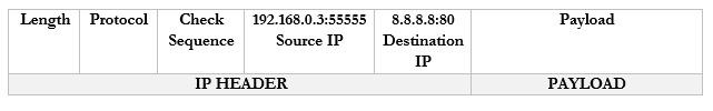
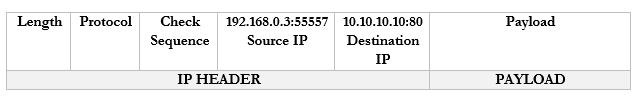
- Our computer wants to access Google.com
- It creates the following packet and packages it into an Ethernet frame, which it sends to the router

- Our router sees the source and destination. It creates an internal translation between the source IP/port and the external IP. It chooses an available external port, in this case 1002.
- 192.168.0.3:55555 -> 44.3.2.1:1002
- 192.168.0.3:55555 -> 44.3.2.1:1002
- Now our router knows that any traffic received on 44.3.2.1:1002 should be forwarded to the internal address/port 192.168.0.3:55555
- The router changes the Source IP/Port in the packet to reflect the external IP/port and forwards it to 8.8.8.8:80
- Google.com receives the packet and sees that it came from 44.3.2.1:1002.
- It creates a packet and replies to 44.3.2.1:1002.
- The router notices that it received a packet on port 44.3.2.1:1002.
- It checks the port mapping table and realizes that this packet belongs to 192.168.0.3:55555
- It changes the destination to 192.168.0.1:80 and forwards the packet. I should say that it wraps the packet inside an ethernet frame (and puts the MAC address of the computer in the destination field).
- The computer receives the packet and sees that it arrived on port 55555. Based on its records, it knows that it was listening for traffic from Google.com on port 55555, and it knows what to do with the traffic.
- If the computer decides to seek traffic from another website (with another port), the router will learn about the traffic and create a new mapping. For example
- 192.168.0.3:55556 -> 44.3.2.1:1003
- 192.168.0.3:55557 -> 44.3.2.1:1004
- 192.168.0.3:55556 -> 44.3.2.1:1003
As we will learn, there are three ways for a device to receive an IP address
- Somebody manually assigns the device a static IP address
- The device automatically receives an IP address from the network through a process known as DHCP
- The device does not receive an IP address and is not programmed with a static IP address. So, it chooses an IP address at random.
Under IPv4, if a device doesn’t have a static IP address and can’t reach a DHCP server, it generates a random IP address in the range of 169.254.0.0 to 169.254.255.255. The process for assigning this address is called link-local address autoconfiguration, auto-IP, or Automatic Private IP Addressing (APIPA). A router will not pass traffic coming from a link-local address.
Under IPv6, every network interface automatically assigns itself a link-local address in the range of fe80::/10, even when it has a routable (static or DHCP) IP address. Link-local addresses are necessary for some IPv6 protocols to function. This is known as a locally unique address because it is possible for devices in other networks to assign the same address. In other words, it will look like the below IP address (where the xxxx’s are unique values).
fe80:0000:0000:0000:xxxx:xxxx:xxxx:xxxx
A link-local IPv4 address is only unique in its own local network, but an IPv6 link-local address is globally unique. Why? A MAC address is considered globally unique (no two devices have the same MAC address). Therefore, if an IPv6 address can be generated from a MAC address, it is also globally unique. The IP address is generated using a process called Extended Unique Identifier 64 (EUI64),
Remember that a MAC address is 48 bits (6 bytes) and follows the format 11:22:33:44:55:66. Like an IP address, a MAC address can be converted into 0’s and 1’s.
The device calculates the new IP address like this
- Let’s say our IPv6 prefix is fe80:0000:0000:0000
- Let’s say our MAC address is 11:22:33:44:55:66
- We split the MAC address in half, and add “fffe” in the middle
- Now our MAC address is 11:22:33:ff:fe:44:55:66
- We flip the seventh bit in the MAC address.
- How can we do that?
- Remember that the MAC address now is 16 characters (or 64 bits) wide. Each octet (separated by a colon) is one byte (8 bits) wide.
- Thus the number “11” is one byte.
- I can represent the one byte as a combination of eight 0’s and 1’s
- 8-bits makes up one byte. A computer with 8-bits can only count to 255 in one operation. If I make a table that is base-two (every entry is double the previous entry), I can combine these eight numbers to make any number from 0 to 255. Below is my table.
| 128 | 64 | 32 | 16 | 8 | 4 | 2 | 1 |
- If you look at the 8-bits in a byte, each bit is assigned to one of the numbers in my table. If the bit is a one, or in “on’ position, then the number is added to the total, and if the bit is a zero, or in the “off” position, then the bit is ignored.
- In this example, I want to convert the number 11. 8+2+1 = 11. If I write in my table that
| 128 | 64 | 32 | 16 | 8 | 4 | 2 | 1 |
| 0 | 0 | 0 | 0 | 1 | 0 | 1 | 1 |
- Then the resulting binary number is 00001011
- The seventh bit is “1”, so I flip it to “0”
- I rewrite my table to reflect the flip
| 128 | 64 | 32 | 16 | 8 | 4 | 2 | 1 |
| 0 | 0 | 0 | 0 | 1 | 0 | 0 | 1 |
- Now I can recalculate the value as 8+1 = 9
- Thus 11 is replaced by 9 and my new MAC address is 09:22:33:ff:fe:44:55:66
- But wait, there’s more!
- We apply this to our IPv6 prefix, and now our globally unique IP address is fe80:0000:0000:0000:0922:33ff:fe44:5566 (I removed some of the colons from the MAC address portion)
An IPv6 address might look like this 2002:0de8:85c3:0010:0300:8b2e:0360:7234.
We can shorten the IP address. If our IP address looked like this: 2002:0de8:0000:0000:0300:8b2e:0360:7234, we could shorten it to 2002:0de8::300:8b2e:0360:7234. See what we did there? We hid the sections with “0000”, and replaced them with ‘::’. In any IPv6 address, we can hide the longest string of 0’s, as long as they fill up an entire segment or as long as a segment starts with 0. We can only hide one string per IP address, otherwise it gets confusing.
If my address looked like this: 2002:0de8:0000:0000:0300:8b2e:0000:7234 and I shortened it to 2002:0de8::8b2e::7234, you now have two “::”, but you don’t know which one had four 0’s and which one had eight.
We can also get rid of any 0’s that are before a “:”. That means 2002:0de8:1824:2383:0300:002e:4e4e:7234 can be shortened to 2002:de8:1824:2383:300:2e:4e4e:7234
Since the IPv6 protocol is still being adopted, not all networks understand it yet. What happens when a router communicating over IPv6 reaches a router that only understands IPv4?
Let’s say that you are trying to access google.com. You’re in Florida and google.com is in California. Your local router understands IPv6 and Google’s router understands IPv6, but the routers in between only understand IPv4.
Your computer and google.com’s server create an IPv4 tunnel and send your IPv6 data through it. The most common tunneling protocol is called 6to4. That is, they package an IPv6 packet inside an IPv4 packet. On the outside, it looks like a normal IPv4 packet, so routers that only understand IPv4 can pass it along, but on the inside it is actually an IPv6 packet, so routers that understand IPv6 can read it.
The problem with tunneling is that it reduces the capacity of each packet (we have to include additional header data, leaving less room for meaningful data).
A better approach is for each device to obtain both an IPv4 address and an IPv6 address. This is known as dual stack. Most modern ISP’s assign both IPv4 and IPv6 addresses to their customers. A device running dual stack will try to connect over IPv6, and if it can’t then it will try to connect over IPv4.
Remember that when an IPv6 capable device connects to a network, it generates the link-local address automatically. Well, after generating the link-local address, the device sends a message to it. This message is known as a Neighbor Solicitation and the purpose is to ensure that no other device is using the same address. If another device is using the address, it will reply with a Neighbor Advertisement message. Otherwise there will be no reply; the device will know that the address is unique and will start using it.
If the address is unique, the device sends a message called a Router Solicitation to ff02::2. All IPv6-enabled routers listen on the ff02::2 address (the long version is ff02:0000:0000:0000:0000:0002). Upon receipt, the router replies with a message called a Router Advertisement. The advertisement contains several pieces of information including
- Whether the router can be used as a default router (default gateway)
- The IPv6 prefix of the link. The prefix allows the device to generate a globally unique IP address.
- The lifetime of the link prefix. The lifetime tells the device how long it can use the IP prefix before generating a new one. This helps with security.
This process is called Stateless Address Autoconfiguration (SLAAC), because each device can configure its own IP address (a router isn’t telling the device what IP address to use). The device will use the process I outlined above (EUI64), but use the prefix provided by the router instead of fe80:0000:0000:0000
A Virtual IP address is an address that is not assigned to a specific network interface. Let’s say I am running a very high availability application, hosted on servers in Atlanta, New York, and Los Angeles. I don’t want any trouble, so even if there is a flood in one city, we continue to operate.
Each server has its own unique IP address (44.1.1.1, 55.1.1.1, and 66.1.1.1). I don’t want any disruptions, so I select a single IP address (7.7.7.7) that points to all the servers.
Instead of pointing it to any server, I point it t a router. The magic inside the router allows it to forward traffic from 7.7.7.7 to any of the server IP addresses. We can add and remove servers in different locations across the world without changing the main IP address.
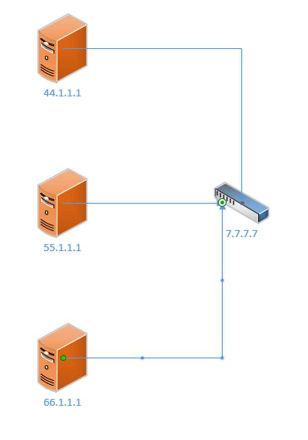
There are many protocols for virtual IP addressing, including Common Address Redundancy Protocol and Proxy ARP.
We can take this a step further and think about subinterfaces. What is the benefit of a subinterface? We might want to assign multiple IP addresses in multiple networks to the same physical interface.
Consider the following example
- I have a local area network with two computers (192.168.0.2, 192.168.0.3) and one surveillance camera (192.168.1.3)
- All the devices are connected to the same switch and are behind the same router/internet connection.
- I don’t want the computers to be able to access the camera, but I don’t want to build a separate physical network for the camera (since I will need a new switch, router, and internet connection)
- Instead I have created two subnets – 192.168.0.0/24 for the computers and 192.168.1.0/24 for the camera
- The router has only one local interface – but I can create two “logical” subinterfaces on it – I assign one of them 192.168.0.1 and I assign the other 192.168.1.1
- Now the computers can communicate with the router through 192.168.0.1 and the camera can communicate with the router through 192.168.1.1, but they can’t talk to each other
- We might call these separate logical networks VLANs. When we look in depth at how the switch functions, we will revisit this topic.
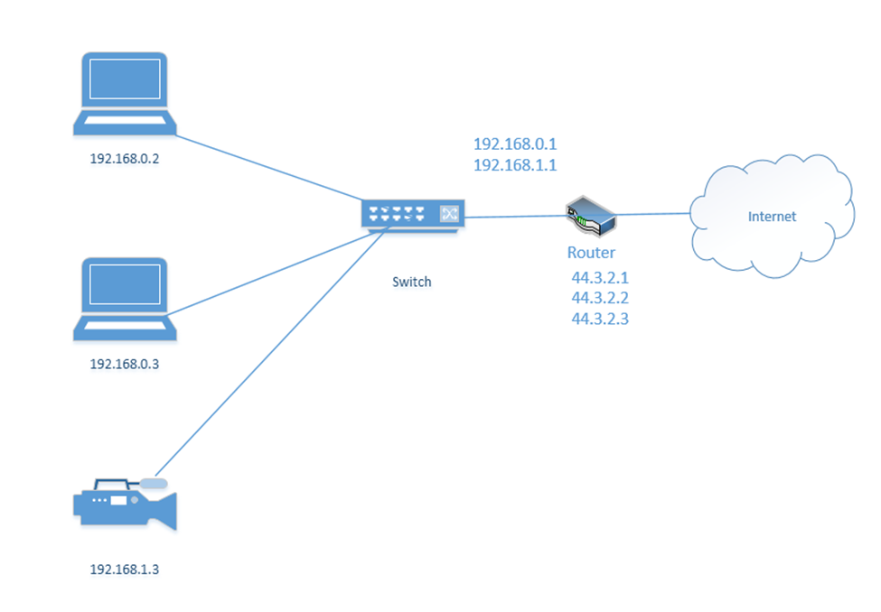
We mentioned ports earlier. Remember that a port is a number that is attached to the end of the IP address. In this case, we aren’t talking about physical ports, but logical ports.
And I mentioned the example that the Google server way in California spends its whole day listening to incoming web traffic. It does so on port 80. That is, it understands that traffic sent to 8.8.8.8:80 is requesting the Google website. It might ignore other traffic, or it might listen for different types of traffic on other ports. For example, it might listen for management traffic on port 300.
Now, let’s say that I have 100 browser tabs open at the same time. I am trying to access Google, CNN, YouTube, etc.. If my computer is bombarded with traffic from all these sources at the same time, it will not know which packet goes where. So, what can it do? It adds a port to the end of each request.
For example, it sends a packet to Google.com with the port 55555 as the source. Google.com knows that it should send a reply back to 192.168.0.3:55555.

It sends a packet to CNN.com with the port 55556 as the source. CNN.com knows that it should send a reply back to 192.168.0.3:55556.
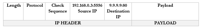
It sends a packet to YouTube.com with the port 55557 as the source. Google.com knows that it should send a reply back to 192.168.0.3:55557.
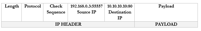
Many common protocols have ports that are reserved for them. If your computer/server is running a specific application, that application will listen for traffic on a specific port (unless you configure it to use a different, non-standard port). There are 65,535 total ports (range is from 1 to 65,535).
Let’s look at some of the most common protocols and their associated ports
| Port Number/Protocol Name | Use |
| 20 and 21/FTP and FTPS | File Transfer Protocol FTP is a protocol for transferring files between two devices FTPS adds a security layer to the file transfer. It requires that the server have an SSL certificate installed. The entire session can be encrypted or only specific portions of it. |
| 22/SSH | Secure Shell Secure Socket Shell (or Secure Shell) allows a user to connect to a remote computer. SSH authenticates the identity of the remote computer to the user and the user to the remote computer. SSH creates a tunnel between the user and the remote computer. The user will require an SSH client such as PuTTY, and the remote computer will require an SSH daemon. Each remote computer must be set up to accept SSH logins (typically over port 22). Network firewalls must be configured to allow traffic over port 22. The user’s IP address should be whitelisted on the firewall (do not allow SSH connections from any IP address) |
| 22/SFTP | SSH File Transfer SFTP is a file transfer protocol within the SSH protocol. Provided that the SSH session is secured and properly configured, then the SFTP session will be as well. |
| 23/Telnet | Telnet Telnet provides a text-based terminal to communicate with a network device or server. Telnet is like SSH but does not contain any security. It is no longer popular due to lack of security. Use SSH instead. |
| 25/SMTP or 587/SMTP over TLS | Simple Mail Transfer Protocol Used to communicate with an e-mail server (for sending e-mail only) Can be secure or insecure, depending on whether the client and server agree to encrypt data between them. SMTP with TLS can be used for encrypted communication. |
| 53/DNS | Domain Name Server Translates Domain Names/Hostnames to IP addresses (necessary to locate network resource) Consider that a human can remember text names (such as google.ca or amazon.com), but for a web browser to access a website, it must figure out the corresponding server IP address. The DNS converts human-readable domain names into machine-readable IP addresses. By default DNS is not secure, but DNS can be run over the HTTPS protocol. |
| 67/68/DHCP | Dynamic Host Configuration Protocol Allows a device to request a dynamic IP from a DHCP server. Allows a DHCP server to dynamically assign IP addresses to other devices. When a device first joins a network, it may not need an IP address and must request one. DHCP does not have a secure alternative, but with proper network security, DHCP messages can be protected. |
| 69/TFTP | Trivial File Transfer Protocol TFTP is like FTP in that it allows a user to transfer files over a network. TFTP has a simple design. An important use of TFTP is to allow a device to boot over a network. A device with no operating system can load one over the network into memory. TFTP does not have any security. |
| 80/HTTP or 443/HTTPS | Hyper Text Transfer Protocol Used to transmit web site data (insecure). The secure alternative is HTTPS HTTPS can use SSL (Secure Sockets Layer) to encrypt the data, or the newer TLS (Transport Layer Security). Both methods use port 443. |
| 110/POP or 995/POP over TLS/SSL | Post Office Protocol Allows an e-mail client like Outlook to retrieve messages from a server. With POP, the e-mail server receives messages on behalf of the user. Via POP, the e-mail client asks the server if there are any new messages. If so, the e-mail client downloads messages from the server. The server deletes the messages after they have been downloaded. POP is no longer common; it has been replaced with IMAP and Exchange, which allow an e-mail client to “sync” with a server. POP can be encrypted with TLS/SSL and run over port 995. |
| 123/NTP or NTS | Network Time Protocol NTP allows network-connected devices to sync their clocks, to within a few milliseconds of UTC. NTP can function accurately even when the network has high latency through the clock synchronization algorithm. NTP can obtain the time from a central server or from a peer. The secure version is called Network Time Security (NTS). |
| 143/IMAP or 993/IMAP | Internet Message Access Protocol Allows an e-mail client to communicate with an e-mail server. The client and server “sync” so that both have the same data (e-mails, calendar entries, contacts, etc.). If an e-mail is deleted in the e-mail client, then it is also deleted on the server. IMAP may be secure or insecure. The secure version uses TLS and port 993. |
| 161/162/SNMP | Simple Network Management Protocol Allows a user to collect and manage data about managed network devices, including routers, switches, servers, and printers. There is no secure version. |
| 389/LDAP or 636/LDAPS | Lightweight Directory Access Protocol Allows users to access different directories Directories include e-mail directories, users, phone numbers, printers, and services The secure version is called Lightweight Directory Access Protocol Secure and uses port 636. |
| 445/SMB/CIFS | Server Message Block/Common Internet File System Allows computers on a network to share files and printers There is no secure version. |
| 514/syslog | Syslog Syslog allows network devices to generate logging messages and send them to a server. This allows an administrator to remotely view logs from many different devices in a centralized location. Syslog can be secured with TLS. |
| 548/AFP | Apple Filing Protocol Allows Apple devices to share files There is no security |
| 1433/SQL Server | Structured Query Language (SQL) Server SQL is a database server developed by Microsoft. It can use TLS to encrypt the communication. |
| 1720/H.323 | H.323 Allows devices to communicate audio-visual content over a network. Used in videoconferencing applications. The communications can be encrypted. |
| 3306/MySQL | MySQL MySQL is a database server developed by Oracle (similar to SQL). It can use TLS to encrypt the communication. |
| 3389/RDP | Remote Desktop Protocol Allows a user to remotely connect to a Windows server or computer via a Graphical User Interface RDP can encrypt the communication if enabled by a user or administrator. |
| 5060/5061/SIP | Session Initiation Protocols Used for real-time communications involving VoIP and video conferencing. Also used by mobile devices for voice over LTE. Encryption is possible when there is a direct connection between the sender and the recipient (which is unlikely). |
Ports 0 to 1023 are well known ports reserved for specific applications. Only those applications should be using those ports. Ports 1024 to 49151 are registered ports. An application developer can apply to have his application use one of those ports. Ports 49152 to 65535 are called dynamic ports or ephemeral ports. An application can borrow one of those ports temporarily if it needs to communicate.
There are four main protocol types. Each protocol can fit into one of the following types.
| ICMP | Internet Control Message Protocol ICMP does not carry user traffic, only machine-to-machine communications. Network equipment use ICMP messages to communicate errors and status with each other. ICMP messages are used by ping and tracert commands for example. |
| UDP | User Datagram Protocol UDP is connectionless, unlike TCP. UDP is good for applications that do not check for errors (or that do not have time to check for errors). Remember that in a communication, the sending device breaks up the data into packets and the receiving device puts the packets back together into something meaningful. If the packets arrive out of order, the receiving device can reorder them. If they arrive damaged, the receiving device can request that they be resent. If you’re downloading a file like an Excel spreadsheet, the sender breaks it up into packets. The receiving computer puts the packets back together. What matters is that the end result makes sense. If you’re on a live video stream or VoIP phone call, the transmission is also broken into packets. Every packet must arrive in the correct order because they are being replayed in real time. If the packets for a video stream or phone call arrived in the wrong order, the call or video wouldn’t make any sense. A poor-quality connection would result in poor video transmission due to errors in the packets but attempting to resend them would be counterproductive. UDP is Transactional (allows a query-response structure, like DNS) Simple (useful for protocols that do not need overhead, like DHCP) Stateless (allows many clients to receive the same connection, good for protocols like IPTV) Lack of retransmissions (no delay caused by retransmissions of missing/incorrect data) Multicast (can broadcast information to many clients, like in service discovery protocols) UDP is like a guy at the top of a hill yelling. He doesn’t keep track of who is listening or whether they received the message. And it’s possible for multiple people to hear him. |
| TCP | Transmission Control Protocol TCP is like a one on one conversation where each participant acknowledges every sentence said by the other participant. If one participant misheard something, it asks the other participant to repeat it. TCP involves a connection between two peers, with a three-way handshake. Each time a peer receives data, it verifies that the data has been received correctly. If not, the recipient requests that the sender retransmit the data. TCP is more reliable than UTP, but it is not useful for real-time applications because it introduces latency into the connection. The TCP Model has four layers that follow the OSI Model Link Layer (Physical and Data Link layers of OSI). TCP doesn’t worry about the link layer, because the protocol doesn’t deal with the physical link. Internet Layer (Network layer of OSI). IP Packets are created on the Internet Layer. Transport Layer (Transport layer of OSI). The transport layer moves the packets. On the transport layer, IP Packets are encapsulated inside segments. Application Layer (Session, Presentation, and Application Layers of OSI). The application layer allows programs to talk to the network. |
| IP | Internet Protocol IP transfers data packets across the internet. IP is considered unreliable because the underlying infrastructure is assumed to be unreliable. Therefore, IP allows a data transmission to adapt to the actual condition of the underlying network. There are two versions of IP in use: IPv4 and IPv6, as we have already seen. IP and TCP normally work together, and are known as TCP/IP |
| GRE | GRE (Genetic Routing Encapsulation) is a tunnel protocol that is used to encapsulate other protocols. The way it works is that a normal data packet is encapsulated inside an IP packet. Routers along the route do not look at the internal packet, only the outside. The final destination looks inside the internal packet. GRE is not secure. |
| IPSec | IPSec (Internet Protocol Security) is a protocol that allows two devices to create a tunnel between them across a normal internet connection. IPSec encapsulated the existing data packet into a larger packet. The interior packet is also encrypted so that routers along the way can’t see inside. |
Connection-oriented protocols require a connection to be established. That is, two devices agree to communicate with each other.
- A connection-oriented protocol is like two people approaching each other at a park and agreeing to have a conversation:
- Person One: “Hey can I talk to you?”
- Person Two: “Sure”
- Person One: “Okay, blah, blah, blah”
- Person Two: “I acknowledge what you said”
- The communication is two ways. The two devices must work to establish the connection, acknowledge the connection and agree on how they will communicate throughout the connection
- The two devices will also mutually agree to end the connection once the communication is complete (or a device can unilaterally end the connection if it doesn’t hear from the other party after some time).
- The communication involves two parties and only two parties
- The recipient acknowledges receipt of each communication
- TCP is a connection-oriented protocol, and uses a three-way handshake to establish the connection)
- The first message is called the SYN (hey can I talk to you?)
- The second message is called the SYN-ACK (yes you can!)
- The third message is called the ACK (I understood that)
- The first message is called the SYN (hey can I talk to you?)
- A connectionless protocol is like one person climbing to the top of a hill and yelling at somebody at the bottom of a hill. Nobody agreed to talk to him. He might talk to only one person, or he might talk to many people. The other person might yell back. The other person might not even be there, in which case he will be talking to himself and not know it.
- The communication is one way
- The communication may be directed at one recipient or many.
- Nobody knows if the intended recipient received the message, because the recipient has no way of acknowledging receipt
- If we’re broadcasting a live video stream, we might use a connectionless protocol because it allows anybody to tune in
- The communication is one way
We are going to look at some more physical network designs. Remember earlier that we had a campus network with three layers? This is a common design in larger networks and consists of three layers.
- Core – the core layer is the backbone of the network. It consists of more advanced switches, which may connect to a router. Core switches connect to the aggregation switches.
- Aggregation – also known as the Distribution layer. This consists of switches that connect the core with the edge.
- Edge – the edge switches are what users connect to. They are also known as access switches.

In a physically large network, having a single core switch would not be possible because it would require a data cable to be run from each part of the facility. In a small network, we may only have one or two layers of switches.
There may be redundant links between each set of switches. When we design our network, we should think about the amount of traffic passing through each switch and between the switches. Ideally, most traffic moves between different devices on the same set of access switches.
The second type of network is a Spine-Leaf. A spine-leaf network can scale better than a three-tier network. Typically, a Spine-Leaf network contains two layers of switches – the Leaf layer connects directly to user devices, while the Spine connects directly to Leaf switches only. No leaf switch connects to another and no spine switch connects to another. We can enlarge the network by adding more spines and more leaves.
A leaf can connect to multiple spines. If the network is small, the leaf might connect to all the spines. Otherwise, it may only connect to some of the spines. The spine is known as the backbone. The path that the traffic takes (which spine a leaf chooses to send fabric to) is chosen at random. This ensures that no spines become overloaded. If a spine fails, the network will continue to function.

When we have a data center with multiple racks, we might decide to install a switch at the top of each rack. This is known as top of rack switching. The switch at the top of the rack is an edge switch and provides access to the devices in the rack. It connects back to an aggregation switch (or to multiple spine switches if we are using the spine-leaf configuration).
In a software-defined network, we don’t have to worry as much about the physical infrastructure. In other words, in a traditional network, each network device has to be programmed separately, and each network device makes independent decisions about how to forward traffic. In an SDN, control of the network is separate from the physical infrastructure.
We create a set of rules that the software then implements across the entire network.
We can think of the SDN as a set of layers
- Application Layer – the application layer contains the rules that manage the network and forward traffic. We create rules in the application layer.
- Control Layer – the control layer connects the application layer to the infrastructure layer. The connection between the controller and the application is called the Northbound interface. The connection between the controller and the infrastructure layer is called the Southbound interface.
The controller takes information from the application layer and translates it into the actual commands that the infrastructure layer will use to forward traffic. - Infrastructure Layer – the infrastructure layer contains the physical devices that are connected. These devices forward traffic based on information given to them by the control layer. The network’s actual capacity is limited to what the infrastructure layer can provide. The infrastructure layer may take the form of a Spine-Leaf or Three-Tier, but usually takes the form of a Spine-Leaf.
- Management Plane – the management plane contains the configuration information for the network. It is separate from the plane that contains the data being forwarded.
- Data Plane – the data plane contains the data that the network is forwarding.
Traffic moving up from the infrastructure layer to the application layer is considered moving “north” while traffic moving from the application layer down to the infrastructure layer is moving “south”. Traffic moving between devices is considered moving East-West (i.e. from server to server).
Looking at SDN’s further (and specifically Cisco’s SDN), the data plane carries user traffic while the control plane carries configuration and monitoring for the network devices. The control plane operates the protocols that help the data plane function.
What does the data plane do?
- Adds and removes Ethernet headers and trunk headers
- Adds and removes IP headers
- Decides how to forward a frame based on its MAC address
- Decides how to forward a packet based on its IP address
- Operates Network Address Translation
- Encrypts and decrypts data
- Establishes a VPN connection
- Enforces the Access Control Lists, Port Security, DHCP Snooping
What does the control plane do?
- Manages ARP
- Manages Spanning Tree Protocol
- Manages Neighbor Discovery Protocol
- Allows a switch to learn MAC addresses
- Manages routing protocols such as OSPF, EIGRP, and BGP
The management plane allows us to configure and monitor the network devices. It includes
- Telnet
- SSH
- SNMP
- Syslog
Inside the switch is a circuit called the Application-Specific Integrated Circuit or ASIC. The ASIC is a custom-designed circuit that only knows how to forward ethernet frames by checking the switch’s MAC address table. We use an ASIC because standard hardware won’t perform as efficiently. This is important because the switch might be forwarding millions of frames per second.
The MAC address table is stored inside the ternary content-addressable memory, or TCAM. The TCAM is a special type of memory that lets us search the table instantly. If we give the TCAM a MAC address, it gives us the matching entries instantly.
The idea now is to use a Software Defined Network to centralize the control of our network. In a traditional network, the control plane is distributed across all the devices. That means that every router or switch makes its own decisions. For example, every router makes its own decisions about forwarding packets, and each switch makes its own decision about forwarding frames.
A centralized control plane can be more efficient. We use a SDN controller. The amount of centralized control varies from network to network. The controller can be anywhere in the physical network, but it must be able to reach every network device.
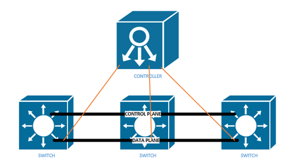
In a controller there are two interfaces
- The Southbound Interface or SBI is the interface between the controller and its devices that it controls. Its name comes from the fact that in network diagrams, the controller sits above the devices that it controls.
The Southbound Interface is not just a physical interface, but also a set of protocols that allow the controller to control network devices. It might also include an API or Application Programming Interface. An API lets two different programs talk to each other. The developer of each program creates a common set of instructions or words that one program can use to talk to another program.
There are many different models of SBIs. The official Cisco SBI is called OpFlex. Other programs include OpenFlow, Telnet, and SNMP. - The Northbound Interface or NBI allows us to read the data inside the controller. We can send commands to the controller, and the controller can send commands to the network devices that it manages.
Technically, the controller can be a software program that is on a server. Another application can connect to the controller via an API. We can create programs or workflows that interact with the controller for monitoring, filtering, or controlling traffic.
A REST API or Representational State Transfer API is one that allows different APIs to exist on different physical devices. The APIs communicate via HTTP or HTTPs messages. We communicate with a Rest API by visiting a specific URL. We will see some examples further in this section.
An API is designed to return structured data. If we understand the format of the data that we will receive, we can write a program to interpret it. The two main API languages are JSON or JavaScript Object Notation and XML, or eXtensible Markup Language.
Our Application sends the Controller a request over its API by sending a message called an HTTP GET URI. The Controller replies with an HTTP GET Response, which includes the data.
There are three main controllers: OpenFlow, OpenDaylight, and Open SDN.
The Open Networking Foundation produces an open-source Software Defined Networking framework called OpenFlow. The Foundation works with many network engineers and vendors of network equipment so that they can help create an SDN framework that works on all devices. That means any brand of network equipment can work with any other brand of network equipment.
OpenFlow defines network devices as abstract ideas with standard capabilities. For example, the idea of a switch is a device that forwards traffic based on its destination MAC address. Most of the control plane is centralized by OpenFlow. The controller and applications that talk to the controller control the network.
The OpenDaylight Controller is an open-source controller based on the ONF Framework. Any SDN controller vendor can use the OpenDaylight Controller as the basis for their own commercial controller. The controller supports several SBIs including BGP and OpenFlow. Any vendor can take this controller and customize it for their own use.
Cisco’s version of the OpenDaylight Controller is called the Open SDN Controller, or OSC, but it is no longer available. The current version is called the Software-Defined Access or SDA and the Software-Defined WAN or SD-WAN (SD-WAN is supported by many other vendors).
When designing an SDN, instead of thinking about the physical layer (Layer 1) of the OSI model, we should focus on the application layer (Layer 7). What resources do applications on Layer 7 need to function? Once we understand that, we can build a network to support them. We call this Application Centric Infrastructure or ACI.
One feature of the new software defined network is not worrying about manually configuring each physical interface. Remember from our earlier part of the book that on a single switch interface, we can give it a speed, duplex, description, ACL, VLAN, make it trusted or untrusted, etc. Across an entire network, we may have thousands or hundreds of thousands of switch ports.
Going back to the beginning of the book, I talked about a Spine Leaf topology. We also call it a Clos network. Each leaf switch is connected to each spine switch, but no leaf switches connect to each other, and no spine switches connect to each other. An end user device connects to a leaf switch. Most of the end user devices will be routers and servers. An end user device can connect to multiple leaf switches.
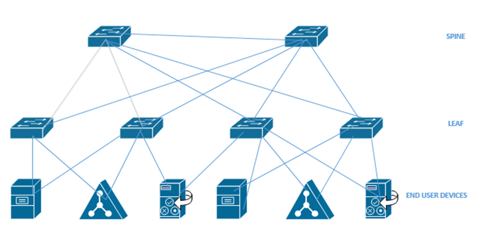
An Application Policy Infrastructure Controller or APIC controls the ACI. ACI uses an Intent-Based Networking model, or IBN. Instead of manually configuring each switch interface, we create some policies that tell the network what type of devices can communicate. The controller analyses these policies and configures the physical network hardware to match the intent of the policies. If we move equipment to other physical locations within the network, the ACI reconfigures the hardware so that it continues to match the intent of the policies.
Think about a large website like Amazon.com
- It has a front-end website that serves the product catalog, pages, reviews, etc.
- It has a content delivery network that provides product photographs, videos, etc.
- It has a database that holds product information, reviews, etc.
- It has a payment application that processes credit cards.
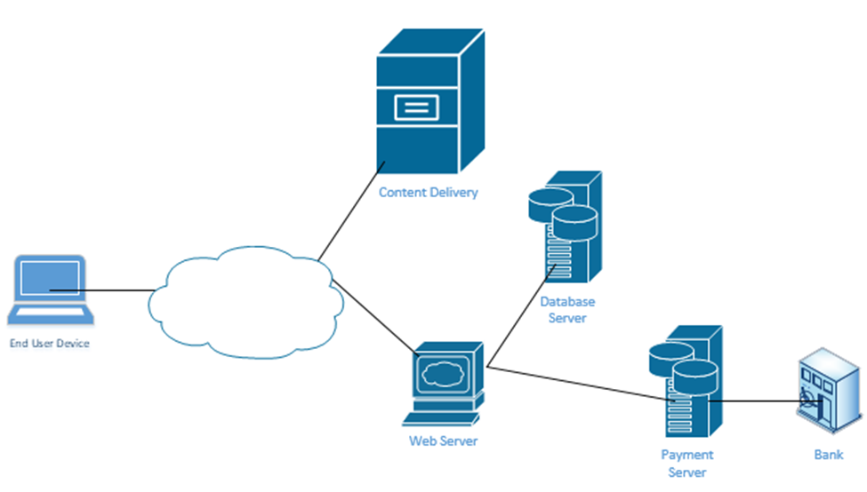
When you visit the website, your computer requests a specific page from the Web Server. Every Amazon product page is just a template. Amazon’s server figures out the product number of the page that you visited and calls up a database that contains the product’s price, properties, and reviews. It fills out the product page template and sends it to your web browser. The page also includes links to photographs. Your web browser manually downloads the photographs from Amazon’s content delivery network and inserts them into the page.
At no time should you be able to directly connect to Amazon’s database – only to its web server and content delivery network. If Amazon uses a controller, it can create these kinds of policies on its network. For example, it would create a policy that allows only web servers and database administrators to connect to its database server.
It’s not that our switch doesn’t have VLANs, access ports, trunk ports, speeds, duplex, or security settings. But we don’t have to worry about it anymore. We just create policies and the APIC creates all the configurations.
In an Enterprise network, we can use the APIC Enterprise Module or APIC-EM. One problem is that many networks have legacy devices that don’t support SDN. Cisco knew that a customer would not purchase an SDN if they had to replace all the underlying network hardware such as switches and routers, thus they introduced the APIC-EM. It allows us to keep the same equipment but configure it via an SDN controller instead of via Telnet, SSN, or a console cable.
What can the APIC-EM do?
- It allows us to automatically map out the topology of our network
- It can show us how data flows through our network (if we provide it with a source and destination, it can create a diagram demonstrating the pathway)
- It can show us how the network makes forwarding decisions at each router or switch interface
- It allows us to automatically configure new devices as soon as they are connected to the network
- It allows us to manage Quality of Service
APIC-EM can’t automatically configure any devices that do not support automatic configuration, but it can automatically configure them via Telnet, SSH, or SNMP. It can also verify the configuration on any device. On legacy devices it can’t make deep configuration changes such as changes to a switch’s MAC address table.
APIC-EM is no longer being sold by Cisco, but it is still in use. As customers continue to upgrade their networks, some will replace their hardware with cloud managed equipment and some won’t.
At the top of our network is our controller. We can connect to it via an App, a GUI, or a Script. The controller connects to the physical network through its Southbound Interface. We call the physical switch structure below the fabric. The fabric contains two components
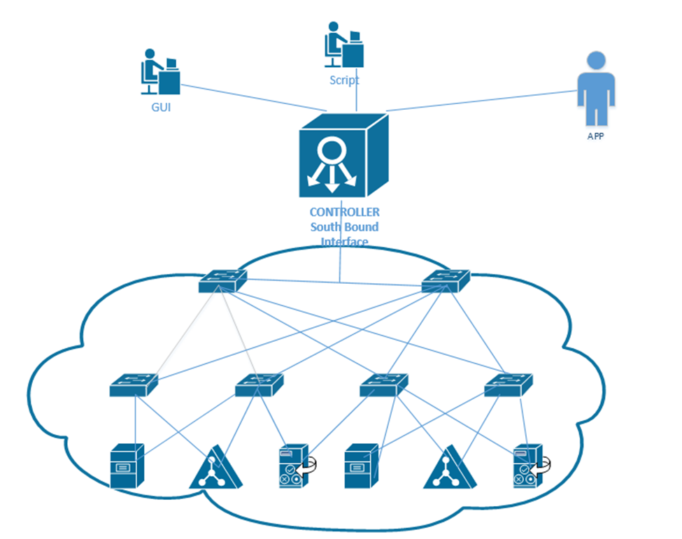
We create a VXLAN tunnel between each switch. The VXLAN tunnel allows end-user traffic to flow through the network. This is supported by the Cisco Virtual Extensible LAN protocol.
A VXLAN is a tunnel that allows end-user traffic to flow through the network. A computer on the left wants to talk to a computer on the right. The switches in the pathway create a VXLAN tunnel between the two devices and transport their traffic.
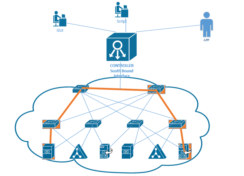
This tunnel is created by the overlay but supported by the physical underlay. We can use an existing network to build an underlay, and add configuration to each device to allow it to support an SDA. This is a cheaper option than purchasing all new devices.
We should make sure that our legacy hardware is compatible with SDA. We should verify that the network devices have compatible operating systems and hardware features for their roles. These roles include
- A Fabric Edge Node. This is a switch that connects to an end user device. It’s like an access switch.
- A Fabric Border Node. This is a switch that that connects to devices that don’t use the SDA. That could include devices like WAN routers.
- A Fabric Control Node. This is a switch or router that helps the control plane operate.
The question is – does your network have the hardware to support the new SDA network? You will need to check the specifications for each device.
If we can’t use the legacy equipment, we can build a new SDA network in parallel to the existing legacy network, and slowly migrate end user devices to the new network. This option is more expensive. More accurately, this option has a higher up-front cost. Eventually, all network hardware is replaced due to failure or age.
We should verify the following hardware features
- How many physical ports do we need and where?
- How fast does each interface need to be – Gigabit, 10 Gigabit, etc.?
- Do we need PoE?
- How much power do we need overall?
- What kind of cabling is installed – cat5e, cat6, multi-mode fiber, single-mode fiber?
- How much overall traffic will the network need to support?
When we connect physical switches in an SDA network, we don’t need to worry about EtherChannels or HSRP. We can use something called a routed access layer design. By default, all LAN switches in an SDA are Layer 3 switches. Cisco DNA will configure the devices to support the routed access layer by default. Any link between two switches is a Layer 3 link. The switches use the IS-IS routing protocol instead of STP or RSTP.
Access switches are located on the edges of the network. Each access switch becomes the default gateway for any end user device that is connected to it.
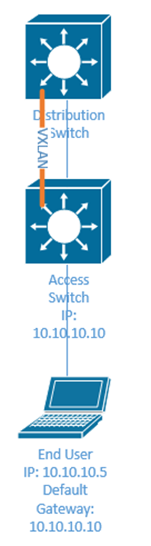
How does a device on an SDA communicate?
- It encapsulates the data in in a frame
- It sends the frame over the fabric (network) and sends it to the Access Switch.
- The Access Switch encapsulates the data inside a VXLAN header and sends it to the destination switch. The other switches in the network forward this frame based on the contents of its header.
- The exit switch (also an access switch) removes the VXLAN header and sends the frame to the end user device (known as an endpoint).
- The switch uses its ASIC to process the VXLAN header; therefore, an SDA doesn’t slow down any switches.
Why do we need an VXLAN? It allows us to encapsulate any type data inside a tunnel and deliver it to its destination. The VXLAN is flexible enough to support a range of header fields so that changes to the protocol can be implemented in the future, without having to make changes to the underlying hardware or software. At the same time, the VXLAN header can be supported by existing equipment.
A VXLAN encapsulates the entire frame, not just the IP packet because it must support Layer 2, not just Layer 3.
The first switch (known as the ingress switch) to receive a frame encapsulates it inside a VXLAN header and sends it through a tunnel to the egress switch.
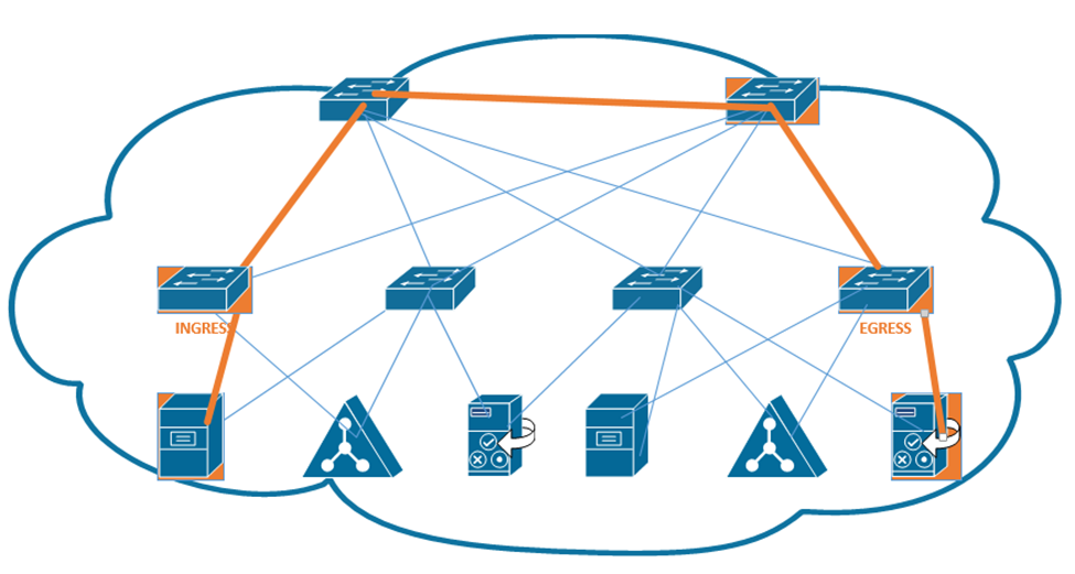
Each switch has two IP addresses – an overlay IP address that uses the same subnet as the end user devices, and an underlay that uses a different subnet. Why? We need to build an underlay subnet that allows the controller to communicate with the switches. We also need an overlay subnet to transport end user data.
In the diagram below, each switch has two IP addresses. One IP address is an overlay IP address in the 10.10.1.0/24 subnet, which transports end user data. The second IP address is an underlay IP address in the 172.172.172.0/24 subnet.
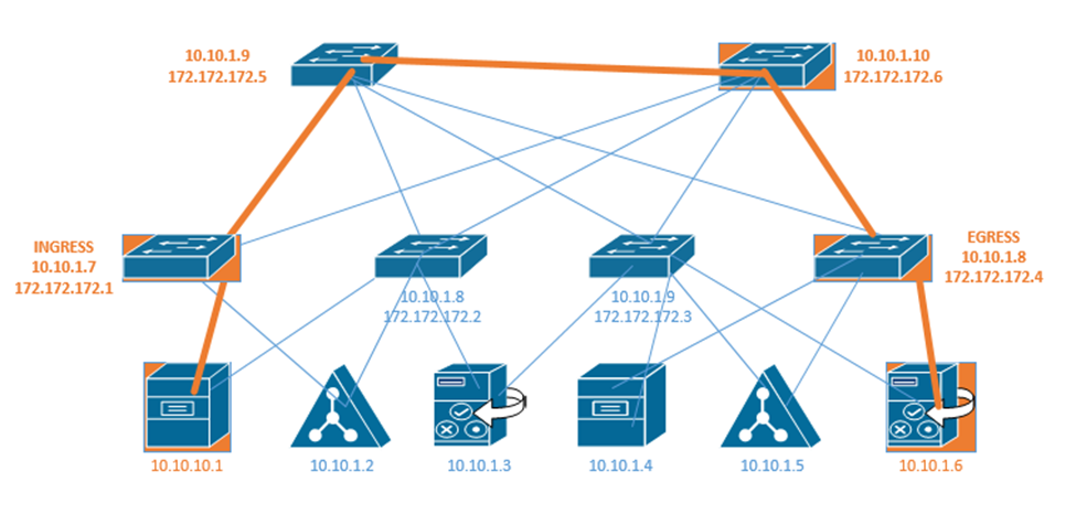
The overlay establishes a pathway in the fabric between two edge nodes. It uses the same IP address space as the endpoints. For example, the Ingress switch sends the end user data to 10.10.1.8.
Remember that a switch uses layer two to learn device MAC addresses from their frames, and that a router uses layer three to learn about neighboring routers through a discovery protocol. We call this the control plane.
Well, access switches (also known as edge nodes) can do the same thing as routers and switches. They can learn about connected endpoints through their MAC addresses, IP addresses, and subnets. Each connected endpoint is given unique ID called the endpoint identifier, or EID.
In our setup we also have a LISP, or Location ID Separation Protocol map server. Each fabric edge node tells the LISP map server about the endpoints that it has identified, and thus its ability to reach them. The server stores this information into a database. Now the server can create a routing locator or RLOC for each device.
That means that the server can identify a pathway to each endpoint. When the fabric needs to send a message to a specific device, it asks the LISP server for the appropriate destination. The LISP server checks its database.
The LISP server holds a database that shows each RLOC and corresponding EID. This database contains the underlay IP address of the edge node and the overlay IP address of the edge node.
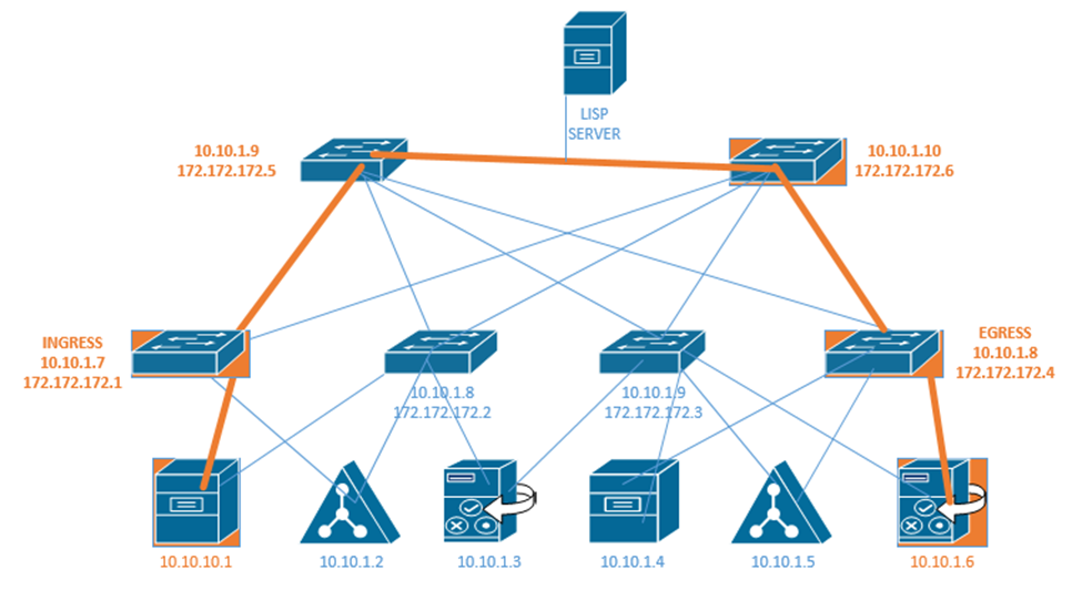
The Ingress Tunnel Router (ITR) receives frames from outside the fabric. It must decide on a tunnel to send the frame to. When it doesn’t know where to forward the frame, the ingress node contacts the LISP server and asks it how to reach the destination. If the LISP server has a destination in its database, it checks the IP address. It calls the egress router in the database and asks it if is still the correct router for that endpoint. The egress router verifies that it is still correct. Now the original ingress can encapsulate the frame with the destination.
In the above example, the LISP server knows that 172.172.172.1 can reach 10.10.10.1 and it knows that 172.172.172.4 knows how to reach 10.10.1.6. If 10.10.10.1 wants to send a message to 10.10.1.6, first the ingress router 172.172.172.1 asks the LISP server if it knows how to reach 10.10.1.6. The LISP server verifies that it does know how to reach 10.10.1.6. It contacts the egress router 172.172.172.4 and asks it if it is still a valid router for 10.10.1.6. If the egress router says yes, then the LISP server tells the ingress router to send its message to 172.172.172.4. The ingress and egress routers establish a VXLAN tunnel to forward their traffic.
The destination in the VXLAN header contains the IP address of the RLOC (172.172.172.4), but the destination of the IP packet contains the IP address of the actual end user device (10.10.1.6).
The next topic we will look at is where we should put our data center and/or server infrastructure. There are four options.
- Branch Office – If we have an organization with several offices, we can group them into branch offices and head offices. The branch offices are smaller. A branch office is one that might be too small to have dedicated infrastructure. It might have a “branch router” and connect back to the main office via a WAN or a VPN. We might store our main servers in the head office, but users can still access them via the WAN or VPN.
- On Premise – We can build a data center in our office. It can be a separate room or separate building. A good data center has multiple internet connections to manage incoming and outgoing connections, battery back up for power, and redundant power supplies. It may also have security and Before we build a data center we must consider
- Whether we have enough equipment to justify the cost of the construction
- The cost of cooling the data center.
- The cost of powering the data center
- Whether we have dedicated staff to operate the data center
- Whether we have adequate internet connections to support the data center
- Whether the function of the infrastructure and the data is too sensitive to outsource to a third party
- Whether we have enough equipment to justify the cost of the construction
- Colocation – If we can’t justify the cost of an on-premise data center, we might outsource it to a colocation. A colocation is where another organization builds a data center and rents out portions of it to other customers. The colocation may charge a flat rate per square foot or per rack unit. The colocation may provide internet connectivity or may require us to provide the connectivity. We are responsible for supplying, installing, and maintaining all of the equipment at the colocation.
- Cloud – The cloud is where we outsource our infrastructure to a third party. We don’t have to worry about the infrastructure, internet, electricity, or physical devices. We will learn more about the cloud in the next section.
When you buy a computer, it will come with a hard drive, which hopefully will have enough capacity to store your data. When you buy a server, it might come with several hard drives, which will hopefully have enough capacity to store your data. What happens when you have too much data and not enough storage capacity? You can buy more servers, but servers are inefficient for storing large volumes of data. Why? A server has other expensive components such as processors and RAM, which are good for processing data. When the purpose of the server is to just store data, we end up wasting money on the other hardware. Servers also usually have limited network connections that can become overloaded.
The solution? A storage appliance. A storage appliance is like a giant box with a large data storage capacity. In reality, it is a special-purpose server with many hard drives. Its only purpose is to store data. When connected to a network, the storage appliance will allow multiple users to store their data on it. We can create multiple “virtual” drives on the storage appliance, each of which can span multiple physical drives. A user or server can connect to a virtual drive on the network almost in the same process as if it were physically connected to his computer.
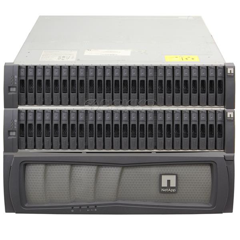
A popular storage appliance is the NetApp. It’s basically a box of hard drives. It’s more complicated than that, but entire books have been written on storage appliances.
A Storage Area Network uses some of the same principles as an ethernet network. A server might connect to both a normal ethernet network (for communicating with users) and a storage area network (for communicating with the storage appliances).
Some concepts
- A Host Bus Adapter or HBA is like a network interface card. It connects the server to the storage area network. The HBA operates on the first layer, known as the Host Layer.
- A SAN Switch is like an ethernet switch, but it forwards traffic between devices on the storage are network
- We call the SAN network devices (switches, routers, and cables) the fabric
- Each device in the SAN has a hardcoded World-Wide Name (WWN) which is like a MAC address in the ethernet world. The switch uses the WWN to route traffic between devices. The switch operates on the second layer, known as the Fabric Layer.
- Switches and HBAs don’t understand what files are. They only see data moving as “blocks”, or groups of 0’s and 1’s.
- SAN networks can operate over copper or fiber links
- The third layer is known as the Storage Layer.
- Each storage appliance is assigned a unique LUN or Logical Unit Number. A storage appliance is a box of hard disk drives. We can subdivide a storage appliance into multiple partitions and assign each partition a unique LUN.
- Each server (or device that can read from or write to a storage appliance) is assigned a LUN.
- We can use the LUN to restrict access from specific servers to specific storage locations. The storage appliance maintains an access control list, which determines (on a LUN by LUN basis) which devices can access each of the storage appliance’s LUNs.
There are many network protocols that can be used for communicating over a SAN
- FCoE or Fiber Channel over Ethernet
- Fiber Channel Protocol
- iSCSI
- SCSI RDMA Protocol
The SAN does not provide “file level” storage, only “block level” storage. That is, a server can’t call up the storage appliance and say something like “give me the file called DraftProposal.docx”, because the storage appliance doesn’t know what files are.
Instead, SAN says to the server, “here is a bunch of storage space, do what you want with it”. The server says, “here is a bunch of data in the form of 0’s and 1’s, put them there, there, and there”. The server must be able to manage the file system. When a user asks the server for the file DraftProposal.docx, the server asks itself “where did I put DraftProposal.docx…oh yeah…I put there, there, and there?”. The server treats the storage appliance like its own hard drive. It may create a file allocation table on the storage appliance to help itself find files.
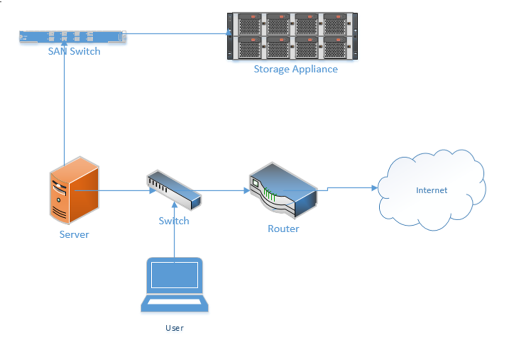
In a less-complicated environment, we could use a NAS or Network Attached Storage device. Like a storage appliance, a NAS is a box of hard disk drives. But unlike a storage appliance, a NAS connects to the ethernet and provides file level storage. A NAS is more like a server that can store data (and does nothing else).
Some protocols that can be used with a NAS
- Apple File System
- Network File System
- FTP
- HTTP
- SFTP
- Server Message Block
Let’s dig deeper into the storage appliance’s connections.
If we didn’t want to build out a separate storage area network, we could use FCoE or Fiber Channel over Ethernet to transmit all our storage data on our existing ethernet network.
FCoE uses 10 Gbit Ethernet to communicate. Just like ethernet, fiber channel uses frames to communicate. When transmitted over FCoE, each fiber channel frame is encapsulated (packaged) inside an ethernet frame, transmitted to the recipient, and then deencapsulated by the recipient.
Each device connected to an ethernet network must have its fiber channel name mapped to a unique MAC address, so that the ethernet network knows where to deliver the data. This can be completed by a converged network adapter or CNA. A CNA is a device that contains a host bus adapter and an ethernet adapter.
A Fiber Channel network communicates between 1 Gbit/s and 128 Gbit/s via the Fiber Channel Protocol. We can create the following types of connections
- Point-to-Point: two devices communicate with each other through a direct cable connection
- Arbitrated Loop: devices are connected in a loop. The failure of a single device or link will cause all devices in the loop to stop communicating. This connection type is no longer used.
- Switched Fabric: devices are connected to a SAN switch. The fabric works like an ethernet network and can scale to tens of thousands of devices.
There are five layers in fiber channel
- The Physical Layer (Layer 0), which includes the physical connections
- The Coding Layer (Layer 1), which includes the transmission/creation of signals
- The Protocol Layer, known as the fabric (Layer 2), which transmits the data frames
- The Common Services Layer (Layer 3), which is not currently used but can be used for RAID or encryption if the protocol is further developed
- The Protocol Mapping Layer (Layer 4), which is used by protocols such as NVMe and SCSI
We use SFPs, SFP+s, and QSFPs with fiber optic cables to connect the various devices in a Fiber Channel network.
iSCSI or Internet Small Computer Systems Interface is another network protocol that allows storage devices and servers to communicate. iSCSI operates over the existing ethernet network without the need for special cabling or adapters. We typically use iSCSI for two purposes
- Centralize our data storage to one or several storage appliances
- Mirror an entire data storage appliance to an appliance in another location to protect in the event of a disaster
The different iSCSI devices
- Initiator. An initiator is a client device such as a computer or server. A software application or driver sends commands over the device’s ethernet adapter in the iSCSI format. For faster communications, a hardware iSCSI host bus adapter can be used.
- Target. A target is a storage device such as a server or storage appliance. A device can be both an initiator and a target.
- Like Fiber Channel, each device is given a LUN or Logical Unit Number.
Some features of iSCSI
- Network Booting. A device can boot from a network operating system and then access an iSCSI target to store and retrieve its data. When the computer boots, instead of looking at its hard disk for the operating system, it contacts a DHCP server that contains a boot image of an operating system. The DHCP server uses the device’s MAC address to forward it to the correct iSCSI device. The iSCSI drive is then mounted to the computer as a local drive.
- iSCSI uses ports 860 and 3260
Security Problems
- iSCSI devices authenticate via CHAP by default but can use other protocols. CHAP is not secure. We will learn more about CHAP later.
- iSCSI devices can be connected over a VLAN so that they are logically isolated from unauthorized users or devices. If we automatically trust all the devices on the VLAN, then a compromised device can gain access to the entire system.
- iSCSI devices can be connected over a separate physical network. If we trust all devices on the physical network, then a compromised device can gain access to the entire system.
- An eavesdropper can spy on the data being transferred over the iSCSI network if the data is not encrypted (and it frequently isn’t).
InfiniBand is another storage area network connection format. InfiniBand is typically used by supercomputers that need a very high level of data transfer and a low latency. It can support transfer rates of up to 3000 Gbit/s. It uses QSFP connectors and copper or fiber cables.
We can also transfer Ethernet over an InfiniBand network.
All Wi-Fi protocols are regulated by IEEE (Institute of Electrical and Electronics Engineers). Collectively, we call them 802.11. As the demand for technology increases, new standards are released. The current standard is 802.11ac.
An access point or client (computer, phone, Wi-Fi adapter) may support multiple standards. The standards are backwards compatible (for example, an 802.11ac device will work with an 802.11a device).
Six standards have emerged
| 802.11a | 1999 Standard Supports up to 54 Mbps in the 5GHz range |
| 802.11b | 1999 Standard Supports up to 11 Mbps in the 2.4GHz range |
| 802.11g | 2003 Standard Up to 54 Mbps in the 2.4GHz range If all the devices on a network are at the 802.11g level, then the network operates at 54 Mbps. Otherwise, it operates at 11 Mbps to support the older devices. |
| 802.11n (Wi-Fi 4) | 2009 Standard Supports multiple-input, multiple-output (MIMO) – an access point device with multiple antennas Up to 72.2 Mbps with one send and one receive antenna Up to 450 Mbps with three send and three receive antennas Also supports transmit beamforming which focuses the signal so that there are no dead zones It has a better way of supporting older devices. It can operate in one of three modes Legacy means it sends separate packets for older devices, which is not efficient Mixed means it sends out standard packets that support older devices and newer devices. We might also call this high-throughput or 802.11a-ht or 802.11g-ht. Greenfield means that it sends out 802.11n packets that support newer devices, but not older devices |
| 802.11ac (Wi-Fi 5) | 2014 Standard Supports multiuser multiple-input, multiple-output (MIMO) Up to 433 Mbps per antenna, or 1.3Gbps with three antennas |
| 802.11ax (Wi-Fi 6) | 2021 standard In addition to all the features of Wi-Fi 5, Wi-Fi 6 offers a 400% improvement in throughput and a 75% drop in latency. It has the best performance in high-density areas such as offices. It takes advantage of cellular technology called orthogonal frequency-division multiple access, which optimizes the radio signal. While the previous Wi-Fi standards operated in the 2.4Ghz and 5Ghz bands, Wi-Fi 6 also operates at 6Ghz (technically 5.925Ghz to 7.125Ghz). |
The standard provides guidelines that manufacturers of wireless devices use when making devices. With a reliable standard, products from different manufacturers all work together. Just think about it – it doesn’t really matter what brand laptop or phone you have, it generally works with the Wi-Fi at your office, your home, the airport, the mall, your friend’s house, etc. That’s because the Wi-Fi card in your device follows the same standard as the Wireless Access Points installed everywhere.
Which Wi-Fi device should you select? Obviously, the latest version is the best! Technology will continue to improve, and you don’t want to be stuck with something that is obsolete by the time you install it.
A radio signal (like the one used in Wi-Fi and cell towers) is like a wave. It goes up and down.
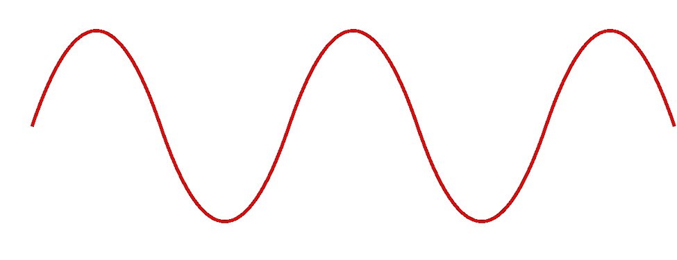
The height of the wave is called the Amplitude. The width of the wave is called the wave length. No matter the height or the width, the wave travels at the speed of light. You can think of a Wi-Fi signal like light that you can’t see, because scientifically, that’s exactly what it is. Thus, the wider the wave (the larger the wavelength), the less waves will pass through each second. We call this the frequency, measured as the number of waves that pass through per second. We measure frequency in Hertz (Hz).
If you had special glasses that would let you see waves in the air, it would look like a big mess of waves travelling everywhere. So, each device is programmed to “look” for waves at a specific frequency and ignore the rest.
The government regulates the frequency that each type of technology can use. If everybody could broadcast signals at any frequency they wanted, the air would be a mess and wireless systems would not be able to function.
Wi-Fi signals travel at a frequency of 2.4GHz and 5GHz (and 6Ghz soon). Older cordless phones use a signal with a frequency of 900MHz.
If we change the Amplitude of the wave over time (up and down), we can use it to convey information.
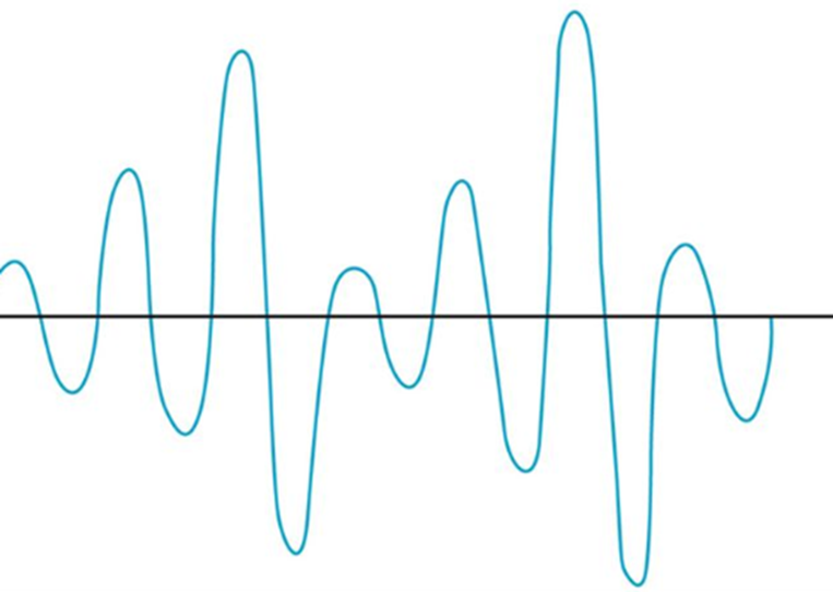
The range of a Wi-Fi signal is between 50 and 300 feet. It is affected by signal interference (noise) from neighboring networks. Different wall types can block or reduce the signal (glass, concrete, steel will block signals more than drywall).
The 2.4GHz range has eleven channels. It has a longer range and is less vulnerable to noise than the 5GHz range, which has twenty-three channels. Older devices use the 2.4GHz range. What’s a channel?
When two waves with the same frequency collide, they cancel each other out and the signal is lost. If I have a Wi-Fi network and my neighbor has a Wi-Fi network, the signals will interfere, and nobody will be able to understand anything. To solve this problem, we divide the 2.4GHz spectrum into 11 channels: Each channel is 22MHz wide, spaced 5MHz apart.
Therefore, a 2.4GHz network is not actually broadcasting at a frequency of exactly 2.4000000GHz, but instead at 2.412GHz, 2.417GHz, or 2.422GHz, etc.
If two neighboring networks choose different channels, they will each broadcast on a slightly different frequency – different enough that their signals won’t interfere. We can manually select the channel that we want to broadcast on, or we can let our wireless system choose it for us. We should survey the neighboring networks to see what channels they are broadcasting on and select a different channel from all of them. If we have multiple access points in a building and their signals overlap, we should select a different channel for each of them.
The channel concept applies to 5GHz networks as well. A 5GHz spectrum is divided into 23 channels, each is 20MHz wide. A 5GHz spectrum can broadcast on 5.150GHz, 5.1570GHz, etc. There are more regulations for the 5GHz network and some countries do not allow some frequencies (they could interfere with weather radar and other systems).
If our network does not have enough bandwidth, we can bond two adjacent channels together to double its capacity. This is known as channel bonding. We combine two 20MHz channels into one 40MHz channel. One of the channels is the primary channel, and the other is secondary. Client devices that use channel bonding will transmit and receive on both channels, while client devices that don’t support it will only use the primary channel.
5GHz has one complication. Some of the frequencies in the 5GHz range are also used by government weather radar systems. If your device is using a frequency in the range of a government radar system, it must first scan to see if such a device is present. If it is, your device must switch to a different channel for at least an hour and then scan again. That is, the government devices get first dibs on some of the 5GHz channels and don’t allow interference from consumer devices. Devices have a feature called dynamic frequency selection (DFS), which allows them to detect the nearby signal and switch over.
High end devices such as smartphones and wireless access points will use dynamic frequency selection. Cheaper devices will not. If a wireless access point switches to a DFS channel, cheaper devices will not be able to detect the signal and will switch to the 2.4Ghz range instead.
Every country regulates the use of wireless signals and some channels that are available for use in the United States are not available in other countries. When you set up a wireless device, you must check the regulations in your country and verify that you are broadcasting in a range that is permitted. Regulations are subject to change and a channel that was legal before may become illegal later.
There are two general types of networks
- An ad hoc network is when two devices try to connect to each other directly. For example, when you connect to a wireless printer, or a wireless access point, you are using an ad hoc network.
- An infrastructure network is one with wireless access points. Devices, known as clients, connect to the network through the wireless access points
The SSID is or Service Set Identifier is the name of the network. An SSID is mapped to a WLAN (Wireless Local Area Network), and a WLAN is typically mapped to a VLAN (Virtual Local Area Network). Multiple SSIDs/WLANs can be mapped to the same VLAN. The purpose of an SSID is to allow us to separate wireless traffic the same way that we can separate wired traffic.
A single wireless access point can broadcast multiple SSIDs. For example, we might have a “Guest” SSID for guests, a “Staff” SSID for staff, and an “IoT” SSID for smart devices. If we have a large office with multiple wireless access points, each wireless access point can be configured to broadcast all the SSIDs.
If I have a large office, one wireless access point won’t be able to provide a good signal across the entire floor. I might place my access points like this, and give each of them a different channel (or the controller might assign each one a different channel automatically). Each access point has its own MAC address, but all are broadcasting the same SSIDs.
What happens when I connect to the “Staff” SSID and I’m standing at the top left corner of the office? My laptop will probably connect to the closest access point (because it has the strongest signal). It might see “Staff” SSIDs from other access points nearby with weaker signals and different channels. As I move throughout the office, the signal from the first access point I connected to will become weaker, but my laptop will automatically move its connection to another wireless access point that is broadcasting the “Staff” SSID. This process is called roaming. When multiple access points create a seamless SSID, it is known as a ESSID or Extended Service Set Identifier.
The BSSID or Basic Service Set Identifier is the name (or MAC address) of the physical access point that I am connected to. Thus, within a given SSID, there can be one or multiple BSSIDs. If an access point is broadcasting multiple SSIDs, then that access point will also have multiple BSSIDs. That is, an access point will have multiple MAC addresses assigned to it by the manufacturer – one physical MAC address that it uses to communicate with the wired network, and multiple wireless MAC addresses that it can assign to each SSID. The number of SSIDs that a wireless access point can broadcast is limited to the number of wireless MAC addresses that are assigned to it.
The portion of the access point that broadcasts the signal is called the radio. An access point can have multiple radios. Having multiple radios allows the access point to communicate with multiple devices at the same time. An access point will need a unique MAC address for each radio-SSID combination. Thus, if an access point can broadcast 32 SSIDs and has two radios, it will have 64 wireless MAC addresses.
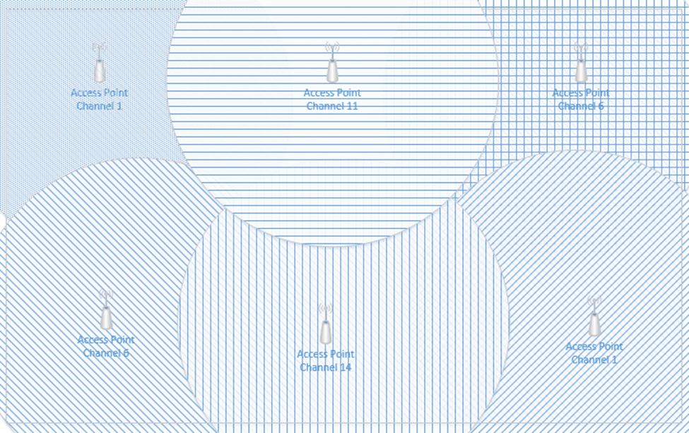
Below is a common Wireless Access Point, the Cisco Aironet 1142N. This access point has antennas concealed inside it. It’s considered omnidirectional, because it broadcasts in all directions. Most access points are omnidirectional. We can mount it to a ceiling and it will provide good coverage in an office.
What if I have a problem where I need to point a Wi-Fi signal in a specific direction? I could attach external antennas to the access point and mount them facing the direction that I require. This is known as unidirectional transmission. Antennas are available in different shapes and sizes. Antennas also increase the signal strength of the access point.
An example of an access point with antennas is below
Another example of powerful directional antennas is the Ubiquiti AirFiber. It allows us to send a strong Wi-Fi signal long distances by pointing it in a specific direction. For example, I could use the AirFiber to connect two far away buildings via a wireless connection.
There are many other types of antennas, each of which has a different pattern and purpose.
How do we secure the communication between the wireless access point and the wireless device? How do we ensure that unauthorized users can’t connect? There are several forms of wireless encryption.
- WEP (Wired Equivalent Privacy) encryption uses a password to authenticate the host with the access point.
- An administrator configures a password on the wireless access point
- The authorized users are provided with the password, which they use to authenticate with the access point
- All further communications are encrypted with the provided password
- A packet sniffer can intercept packets and easily crack the password.
- WEP has been known to be insecure since 2005 but is still in use today.
- WPA keys were 64-bits long.
- WEP is not recommended
- An administrator configures a password on the wireless access point
- WPA (Wi-Fi Protected Access) and WPA2 use a password to create a handshake (which creates a unique one-time password) between the host and the access point.
- An administrator must create a WPA or WPA2 password and configure it on each access point
- The authorized users are provided with the password, which they use to authenticate with the access point
- When a device first connects to a wireless access point, the device and the WAP follow a handshake process to create a unique one-time key that the two parties use to encrypt all further communications
- WPA is more secure than WEP because the key is much longer and because every connection is encrypted with a different password
- A packet sniffer can intercept packets during the handshake process and identify the password.
- WPA uses 256-bit keys
- WPA2 uses AES encryption algorithms and has replaced WPA
- An administrator must create a WPA or WPA2 password and configure it on each access point
- WPA Enterprise uses a RADIUS server to authenticate the identity of the host attempting to connect. The host will typically present a digitally signed certificate to the RADIUS server (i.e. the host computer must have a certificate installed to connect to the network). Another option is for the host to sign in to the wireless network by entering a username and password. Certificate-based WPA Enterprise is difficult to break, provided that the certificates are digitally signed using a strong algorithm and that there are no other flaws in the access point or RADIUS server. Username/password based WPA Enterprise can be broken if the username/password are intercepted. An attacker could set up a rogue access point broadcasting the same SSID and then intercept usernames/passwords.
- WPA3 is under development but is expected to replace WPA2.
- TKIP (Temporal Key Integrity Protocol) was a standard that was introduced to temporarily replace WEP.
- WEP had been broken and the Wi-Fi alliance needed a quick solution to replace it without forcing customers to replace physical hardware
- TKIP is no longer considered secure
- TKIP uses the same functions as WEP, except that it
- Adds an initialization vector to the secret key
- Uses a sequence counter to prevent replay attacks
- Uses a 64-bit Message Integrity Check
- Encrypts every data packet with a unique encryption key
- Adds an initialization vector to the secret key
- WEP had been broken and the Wi-Fi alliance needed a quick solution to replace it without forcing customers to replace physical hardware
Remember that Wi-Fi is considered a “one-to-many” connection. One antenna talks to many devices. But as I said before, a wireless access point can only communicate with one device at a time.
Access points use Time Division Multiplexing. The access point sends data to one device, pauses, sends data to the next device, pauses, sends data to the third device, pauses, etc. until it has sent data to all the devices. It is also receiving data from each device in the same pattern.
To send data to multiple devices at the same time, an access point must have multiple antennas and engage in advanced signal processing. This technology is known as Multiple Input, Multiple Output (MIMO).
How does it work?
- Remember that if we send multiple radio signals at the same time, they can either merge and become more powerful, or they can cancel each other out. Whether they merge or cancel each other out depends on the way that they are sent.
- Beamforming is an idea that we can send out signals from multiple antennas in a way that they can all combine at the receiver as a more powerful signal. The receiver uses an algorithm to amplify amplifies the different signals by giving each one a different weight.
- There are three ways
- Precoding – the access point sends out the same signal through multiple antennas. Each signal is given a different phase and weight so that the signals combine at the receiver to have the maximum power.
- Spatial Multiplexing – the access point splits a high-bandwidth signal into multiple low-bandwidth signals. Each signal is transmitted from a different antenna. Spatial multiplexing is good when there is a high level of noise. The receiver splits the signals into channels and interprets the data.
- Diversity Coding – the access point sends the same signal through multiple antennas, but each signal is sent orthogonal to the other ones (at right angles). That means, regardless of how the receiver is facing, it will receive at least one signal correctly.
- Precoding – the access point sends out the same signal through multiple antennas. Each signal is given a different phase and weight so that the signals combine at the receiver to have the maximum power.
We can take this a step further and use a Multi-User MIMO (MU-MIMO). What happens when we want to use MIMO with multiple users at the same time? The access point can divide the signals spatially so that it can serve multiple users at the same time, provided they are some distance apart. When multiple users close together, the signals cannot be separated easily, and those users must share the bandwidth.
Wi-Fi 6 allows MU-MIMO to function in both directions. Previous versions allowed multiple users to be served quickly when downloading, but Wi-Fi 6 allows multiple users to upload data at the same time.
When selecting wireless devices, consider the following
- Purchase wireless access points that support Wi-Fi 6 and MU-MIMO
- As the use of Wi-Fi increases, consider purchasing wireless access points that support a 2.5 Gbit/s or 5 Gbit/s ethernet connection.
- Determine the range of each access point and the area that you must cover; this will allow you to calculate the number of access points required
- Determine the number of devices or users that need to be served and the maximum capacity of the wireless access point
- Consider whether the area that requires coverage has a basic layout or whether specific directional antennas are required
A cellular antenna in a tower can only talk to one phone at a time. How do we connect multiple phones to a tower at the same time? What if everybody is at the Super Bowl and texting and talking and tweeting?
There are three types of cellular network connections – GSM (Global System for Mobile Communications), TDMA (Time Division Multiple Access), and CDMA (Code Division Multiple Access).
A cellular phone connects to a tower through its cellular modem. The phone will contain a SIM card that allows it to authenticate with that network. Some laptops and routers also support cellular connections.
A cellular phone may be locked to a specific cellular network (Bell, Telus, AT&T, Verizon, etc.) or unlocked (in which case it can connect to any network). You pay for a cellular plan with a specific carrier (Bell, Telus, AT&T, Verizon, etc.), which could include any number of features.
Some cellular phones have room for two SIM cards. A cell phone with two SIM cards can connect to two networks at the same time (or maintain two separate connections to the same network).
When a phone is outside the range of its default network (for example, when it is in another country), it is roaming, and will attempt to connect to any number of available networks. The user may incur additional charges for roaming.
GSM and CDMA are the two main types of cellular radio networks. Most cellular networks are GSM, except for those maintained by Sprint and Verizon. Some phones can operate on both GSM and CDMA networks. A carrier will operate their radios on several different frequencies (for example, Sprint operates over the CDMA 800 MHz and 1900 MHz frequencies). For a phone to connect to a carrier’s network, it must have a modem that operates on at least one of that carrier’s frequencies.
TDMA was an older cellular technology that has been incorporated into GSM. With TDMA, a cellular antenna would give each cell phone a time slot. The width of each slot is measured in milliseconds. Each phone would only listen during its slot. This way the tower can connect multiple phones at the same time. It’s like a person trying to have a conversation with several other people: say a few words to person one, say a few words to person two, say a few words to person three, come back to person one and say a few words, etc.. Each of the other people only needs to listen when they are being talked to.
GSM continues to use the same time slots that TDMA did. GSM data uses the GPRS (General Packet Radio Service) protocol, which is no longer considered secure.
CDMA is more complicated. It involves complicated math, linear algebra to be specific. You can think of the signal from a cell tower to a phone like a wave. Each phone agrees on a code with the tower. The tower creates a signal that is a mash of all the messages that it wants to send each phone; the messages are coded so that they don’t cancel each other out. Every phone receives the same signal but extracts its own portion from it. It’s like if I hid French words between all the English words in this book. An English-speaking person would read the English words and a French-speaking person would read the French words. Now imagine that I hid words from eighty different languages in this book. Every person could see all the words but only understand their own language.
There are several cellular network technologies/speeds
- 3G – 3G is also known as Third Generation. It provides data transfer rates of at least 144 kbit/s.
- 4G – 4G is also known as Fourth Generation. 4G must use an underlying IP network, and provide data speeds of up to 100 Mbit/s for moving users and 1 Gbit/s for stationary users.
- 5G – 5G is also known as Fifth Generation. It provides data rates of up to 1 Gbit/s. 5G is supposed to provide enough bandwidth to allow devices to function as primary internet connections. 5G broadcasts signals at 24 Ghz to 40 Ghz.
- LTE – LTE is also known as Long Term Evolution. It is an advancement of the 3G network, but does not meet the standard of 4G. LTE provides download speeds of up to 299 Mbit/s. It also requires IP packet switching for both data and voice calls.
Some phones support both GSM/CDMA and either 3G/4G/5G/LTE. GSM/CDMA are becoming less popular as 5G takes over.
When selecting a phone
- Ensure that the phone’s modem is compatible with the chosen carrier
- Ensure that the carrier has adequate network coverage in the areas you plan to visit
- Ensure that the cost of the cellular data and voice plan is known in advance
Cellular (data-only) connections are used by mobile workers and by cellular modems. It is common for an organization to install a primary broadband modem and a back up cellular modem. If the primary connection fails, the cellular back up will take over.