
2.1 Compare and contrast Transmission Control Protocol (TCP) and User Datagram Protocol (UDP) ports, protocols, and their purposes.
- Ports and protocols
- 20/21 – File Transfer Protocol (FTP)
- 22 – Secure Shell (SSH)
- 23 – Telnet
- 25 – Simple Mail Transfer Protocol (SMTP)
- 53 – Domain Name System (DNS)
- 67/68 – Dynamic Host Configuration Protocol (DHCP)
- 80 – Hypertext Transfer Protocol (HTTP)
- 110 – Post Office Protocol 3 (POP3)
- 137-139 – Network Basic Input / Output System (NetBIOS)/NetBIOS over TCP/IP (NetBT)
- 143 – Internet Mail Access Protocol (IMAP)
- 161/162 – Simple Network Management Protocol (SNMP)
- 389 – Lightweight Directory Access Protocol (LDAP)
- 443 – Hypertext Transfer Protocol Secure (HTTPS)
- 445 – Server Message Block (SMB) / Common Internet File System (CIFS)
- 3389 – Remote Desktop Protocol (RDP)
- TCP vs. UDP
- Connectionless
- DHCP
- Trivial File Transfer Protocol
- Connection-Oriented
- HTTPS
- SSH
- Connectionless
What is a Port and Protocol?
We can’t just talk about ports and protocols until we know what networks are. The question we want to ask is: how does data on a network (or on the Internet) get from one point to another? How is it that when you plug a computer into an ethernet jack or connect to the Wi-Fi in a building, things just work (usually)? How do devices understand each other?
Well, manufacturers create devices according to established standards. Devices communicate with each other based on specific protocols (languages) that are defined by the international community. If you get into the business of making ethernet adapters, patch panels, fiber optic cables, switches, routers, etc., you will also have to follow those standards and protocols so that your devices can communicate with all the existing devices.
To create these standards and protocols, we had to create a model of the network. The OSI (Open Systems Interconnection) model is the single most important concept you will need to know (to pass the exam). OSI is just a concept.
There are seven layers:
- Layer 1 – Physical
- Layer 2 – Data Link
- Layer 3 – Network
- Layer 4 – Transport
- Layer 5 – Session
- Layer 6 – Presentation
- Layer 7 – Application
We are going to see some examples of communications that allows this model to make sense. But each layer carries data for the layers below it. Or in other words, each layer packages (encapsulates) the data from the layer below it. So, a device or program on the Application layer creates content and addresses it to a device on the Application layer at the other side. It gives this content to a device Presentation layer, which packages it, addresses it to the device in the Presentation layer on the other side, and sends it a device on the Session layer. This goes on until we get to the Physical layer.
When the data is received by the Physical layer on the other side, it is unpackaged and sent up the devices on each layer until it is received by the Application layer.
We need to understand the layers so that
- We can design a network and make sure that all the devices are connected and that they can communicate with each other properly
- We can identify which layer is affected when something goes wrong. This way, we can properly troubleshoot the software or configuration that is causing the issue
- We can start troubleshooting at the bottom layer and work our way up, or start at the top layer and work our way down, or figure out what is the highest layer that is working and then troubleshoot the next layer above it
Let’s look at an example. You want to send an e-mail. The Layer 7, Application Layer is the software that a user sees (Microsoft Word, Google Chrome, etc.). You type up the e-mail in Microsoft Outlook and send it off. But what is really happening? You only saw the seventh layer.
Well, Layer 6 is the Presentation Layer. It takes the data from Layer 7 and makes sure that the Application layer of the recipient can understand it. What if the recipient’s computer has a Mac or Unix operating system? What if the user doesn’t use HTML to display e-mails? What if the user’s computer is in a different language?
Idea: If you type up a document in Microsoft Word and then open it in Notepad, it will look like gibberish. Why? Because Microsoft Word has its own internal language that keeps track of things like fonts, formatting, layout, highlights, etc.. This language is useless to humans. Humans just want to see the properly formatted Word document or e-mail. So, the Presentation layer takes this gibberish that the computer understands and converts it into something that a human understands. If you open the same e-mail on your phone, or tablet, or 24” monitor, it will look different. The Presentation Layer on each device understands the capabilities of that device and translates the gibberish into a format that is suitable for that device’s Application layer.
Layer 5 is the Session Layer. What is a Session? A Session is when two devices agree to communicate with each other for a period. When you send the e-mail, your computer calls up the receiving computer and says, “hey, I want to send you an e-mail”. The two computers use the session to exchange data and keep it open until one or both decide to close it. Technically (as we will find out layer), your computer wouldn’t directly contact the recipient’s computer. It would call up the e-mail server of its own service provider and send the e-mail there. That e-mail server would call the e-mail server of the recipient and send the e-mail there. The receiving e-mail server would call up the recipient’s device and further transport the e-mail. We just tried to make it simple for this example.
Layer 4 is the Transport Layer. Layer 4 takes the data from the Session Layer and packages it or breaks it into pieces. So, it might cut up your e-mail into chunks, give each one a number, and send each chunk separately to the recipient. The recipient has already agreed to receive these chunks because it has an established session. The Transport Layer on the other side would put them back together in the correct order. If some of those chunks don’t show up, the sending Transport Layer can send them again. The Transport Layer also puts the IP address of the recipient on each chunk. Later, we are going to look more specifically at a transport protocol known as TCP/IP.
Layer 3 is the Network Layer. Say you are in New York City, and you are sending an e-mail to a device in Los Angeles. Layer 4 put the IP address of the recipient on each “chunk”. How does the data get to the destination? Throughout the internet are many routers and many cables. So, there are many pathways for data to get from NYC to LA. The router in your office looks at the destination IP address and decides about the next router to send the e-mail to (probably the main NYC router for your ISP). That router receives the data and makes its own decision sending it to a router in California. A main router in California sends the data to a router in LA. Finally, a router in LA forwards that e-mail to the recipient’s office router. Routers have algorithms that make these decisions efficient (these protocols are known as OSPF and BGP, but they are beyond the scope of this book).
In the Layer 3, we call each “chunk” of data a packet. We will find out later that a packet has a very specific format so that routers can understand them. The size of the packet is known as the Maximum Transmission Unit. The sender and recipient agree on the largest size of packet that they can handle.
You can think of this layer like the mail. If you send a letter from NYC to LA, a mailman isn’t going to pick up the letter and drive straight to LA with it. Instead, that letter will go to the local NYC post office no matter the destination (just like your local office router must process all the outgoing data no matter the destination). The local post office sorts mail going to California and ships them off to a main post office in California. That post office sorts the mail going to LA and ships them to the main LA post office. The main LA post office sorts the mail into routes for trucks and letter carriers, and one of those trucks and letter carriers deliver your letter to the recipient.
Layer 2 is the Data Link Layer. Layer 2 allows two directly devices to communicate. Every network device has a unique address called a MAC address. This address is burned into the device from the factory and is unique regardless of the manufacturer. Layer 2 uses MAC addresses to forward traffic.
Remember those chunks called packets? Well, your computer doesn’t send packets. It creates the packet and puts the destination IP address on it, but your computer doesn’t know how to get it to California. So, the destination IP address is kind of useless to your computer.
Instead, your computer thinks about the next destination of the packet. It might be the same office, an office across the street, or an office in another country. As we will find out later, your computer just needs to think about whether the destination is within the office or outside the office (or in other words, whether it is behind the router or past the router).
Your computer finds out the MAC address of the packet’s destination. Then the computer packages this packet into a frame and adds the destination MAC address. If the destination is within your office, your computer puts the destination MAC address of the actual recipient. If the destination is somewhere else, your computer won’t be able to figure out the destination MAC address, so it puts the destination MAC address of the router as the recipient. The router receives this frame and removes the packet. Then it figures out the MAC address of the next destination (probably the next router). It puts the packet into a new frame with a new MAC address as the destination.
Your computer might be connected directly to your office router, but most likely it will connect to a switch. The switch understands and forwards frames based on the MAC address. We will find out more about how switches work later. When you send a frame to a device within your office, the switch can deliver that frame without having to talk to the router. When you send a frame addressed to the router (i.e., a frame containing a packet that has a destination outside of your office), the switch delivers that frame to the router.
In the case of our e-mail example, your computer encapsulates the packets containing pieces of your e-mail into frames. It puts the MAC address of your office router as the destination. The office switch delivers those frames to the router. The router removes the packet from the frame. The router finds the MAC address of the next router and packages the packet into a new frame. It puts the MAC address of the next router into the destination field on the new frame and sends it along. This process continues until the frame is finally delivered to the destination.
Layer One is the Physical Layer. It is the actual transmission layer and contains the wiring. Layer One also deals with directly connected devices. When your computer tries to send data to the switch, your computer and the switch must agree on a speed. What if your computer or the switch can’t handle a speed that is too high? Thus, two directly connected devices must agree on the speed to use on the line. If the line supports only a one-way transmission, they must also agree who will talk and who will listen at each time.
Now let’s think about the router in the receiving office. The Physical Layer receives the data (0’s and 1’s as an electronic or fiber transmission). That data is eventually recorded into a frame on Layer Two. The router’s Layer Two receives the frame. The router’s Layer Three technology removes the packet from the frame and figures out the destination MAC address of the device in the office that is entitled to it. It repackages the packet into a frame with the new destination MAC address and forwards the frame.
The switch in the office receives the frame and forwards it to the correct computer. The receiving computer removes the packet from the frame and sends it to the Transport Layer. The Transport Layer waits until all the associated packets are received and reassembles them. It also asks for missing packets to be resent (if any). The Transport Layer sends this assembled data to the Session Layer. The Session Layer sends the data to the Presentation Layer, which understands that the data is an e-mail. The Presentation Layer thinks about the best way to translate the content for the Application Layer. The Application Layer displays the e-mail in the recipient’s web browser or e-mail application.
When the router puts a packet into a frame, it is called encapsulation. When a router removes a packet from a frame, it is called deencapsulation. We are going to use those words more often throughout the book.
A port is a number that is attached to the end of the IP address. We will learn more about IP addresses later. In this case, we aren’t talking about physical ports, but logical ports.
Imagine that the Google server way in California spends its whole day listening to incoming web traffic. It does so on port 80. Let’s say that the Google server has an IP address of 8.8.8.8. It understands that traffic sent to 8.8.8.8:80 is requesting the Google website.
It might ignore other traffic, or it might listen for different types of traffic on other ports. For example, it might listen for management traffic on port 300. Or if an admin is trying to remote into the server to perform some updates, he will use port 3389. So, he will set his remote software to access the server on 8.8.8.8:3389.
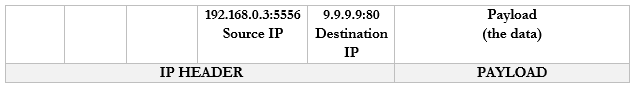
Now, let’s say that my IP address is 192.168.0.3, and I have 100 browser tabs open at the same time. I am trying to access Google, CNN, YouTube, etc.. If my computer is bombarded with traffic from all these sources at the same time, it will not know which packet goes where. So, what can it do? It adds a port to the end of each request.
For example, it sends a packet to Google.com with the port 55555 as the source. Google.com knows that it should send a reply to 192.168.0.3:55555. This is technically wrong. I skipped a step. 192.168.0.3 is an internal IP address and there is some routing or Network Address Translation that has to take place on my router. We will get into the details of how IP addresses work in a later section.

It sends a packet to CNN.com with the port 55556 as the source. CNN.com knows that it should send a reply to 192.168.0.3:55556.
It sends a packet to YouTube.com with the port 55557 as the source. YouTube.com knows that it should send a reply to 192.168.0.3:55557.

Many common protocols have ports that are reserved for them. If your computer/server is running a specific application, that application will listen for traffic on a specific port (unless you configure it to use a different, non-standard port). There are 65,535 total ports (range is from 1 to 65,535).
Some of the most common protocols are summarized in the following table. Remember that an administrator can run a protocol over a non-standard port number.
| Port Number/Name | Use |
| 20 and 21/FTP | File Transfer Protocol FTP is a protocol for transferring files between two devices FTPS adds a security layer to the file transfer. It requires that the server have an SSL certificate installed. The entire session can be encrypted or only specific portions of it. |
| 22/SSH | Secure Shell Secure Socket Shell (or Secure Shell) allows a user to connect to a remote computer. SSH authenticates the identity of the remote computer to the user and the user to the remote computer. SSH creates a tunnel between the user and the remote computer. The user will require an SSH client such as PuTTY, and the remote computer will require an SSH daemon. Each remote computer must be set up to accept SSH logins (typically over port 22). Network firewalls must be configured to allow traffic over port 22. The user’s IP address should be whitelisted on the firewall (do not allow SSH connections from any IP address) |
| 22/SFTP | SSH File Transfer SFTP is a file transfer protocol within the SSH protocol. Provided that the SSH session is secured and properly configured, then the SFTP session will be as well. |
| 23/Telnet | Telnet Telnet provides a text-based terminal to communicate with a network device or server. Telnet is like SSH but does not contain any security. It is no longer popular due to lack of security. |
| 25/SMTP | Simple Mail Transfer Protocol Used to communicate with an e-mail server (for sending e-mail only) Can be secure or insecure, depending on whether the client and server agree to encrypt data between them. |
| 53/DNS | Domain Name Server Translates Domain Names/Hostnames to IP addresses (necessary to locate network resource) A human can remember text names (such as google.ca or amazon.com), but for a web browser to access a website, it must figure out the corresponding server IP address. The DNS converts human-readable domain names into machine-readable IP addresses. |
| 67/68/DHCP | Dynamic Host Configuration Protocol Allows a device to request a dynamic IP from a DHCP server. Allows a DHCP server to dynamically assign IP addresses to other devices. When a device first joins a network, it may need an IP address and must request one via DHCP. |
| 69/TFTP | Trivial File Transfer Protocol TFTP is like FTP in that it allows a user to transfer files over a network. TFTP has a simple design. An important use of TFTP is to allow a device to boot over a network. A device with no operating system can load one over the network and into its memory. |
| 80/HTTP | Hyper Text Transfer Protocol Used to transmit web site data (insecure) |
| 110/POP | Post Office Protocol Allows an e-mail client like Outlook to retrieve messages from a server. With POP, the e-mail server receives messages on behalf of the user. The e-mail client asks the server if there are any new messages. If so, the e-mail client downloads messages from the server. The server deletes the messages after they have been downloaded. POP is no longer common; it has been replaced with IMAP and Exchange, which allow an e-mail client to “sync” with a server. |
| 123/NTP | Network Time Protocol NTP allows network-connected devices to sync their clocks, to within a few milliseconds of UTC. NTP can function accurately even when the network has high latency through the clock synchronization algorithm. NTP can obtain the time from a central server or from a peer (another device on the network) |
| 137-139/NetBIOS/NetBT | NetBIOS/NetBT Developed by Microsoft in the 1980s. Allows computers to communicate with each other over a network and exchange basic information. When a computer boots up, it broadcasts its information (MAC address and hostname) so that other computers on the network can find it. NetBIOS only worked for small networks of up to 40 devices, with no router. NetBIOS over TCP/IP (or NetBT) was an upgrade to NetBIOS. It provides name services (provides each computer with a unique hostname), and communications. |
| 143/IMAP | Internet Message Access Protocol Allows an e-mail client to communicate with an e-mail server. The client and server “sync” so that both have the same data (e-mails, calendar entries, contacts, etc.). If an e-mail is deleted in the e-mail client, then it is also deleted on the server. IMAP may be secure or insecure depending on how the server is configured. |
| 161/162/SNMP | Simple Network Management Protocol Allows a user to collect and manage data about managed network devices, including routers, switches, servers, and printers. |
| 389/LDAP | Lightweight Directory Access Protocol Allows users to access different directories Directories include e-mail directories, users, phone numbers, printers, and services |
| 427/SLP | Service Location Protocol Allows computers to find services on a local network A device will broadcast a URL containing the location of a service that it offers over SLP Other devices can connect to the URL over SLP to use the service |
| 443/HTTPS | Hyper Text Transfer Protocol-Secure Used to transmit web site data securely. |
| 445/SMB/CIFS | Server Message Block/Common Internet File System Allows computers on a network to share files and printers |
| 548/AFP | Apple Filing Protocol Allows Apple devices to share files |
| 636/LDAPS | Secure Lightweight Directory Access Protocol Like LDAP but secure |
| 1720/H.323 | H.323 Allows devices to communicate audio-visual content over a network. Used in videoconferencing applications. |
| 3389/RDP | Remote Desktop Protocol Allows a user to remotely connect to a Windows server or computer via a Graphical User Interface |
| 5060/5061/SIP | Session Initiation Protocols Used for real-time communications involving VoIP and video conferencing. Also used by mobile devices for voice over LTE. |
Ports 0 to 1023 are well known ports reserved for specific applications. Only those applications should be using those ports.
Ports 1024 to 49151 are registered ports. An application developer can apply to have his application use one of those ports.
Ports 49152 to 65535 are called dynamic ports or ephemeral ports. An app can borrow one of those ports temporarily if it needs to communicate.
An IP address combined with a port is called a socket.
Protocol Types
There are four main protocol types. Each protocol can fit into one of the following types.
| ICMP | Internet Control Message Protocol ICMP does not carry user traffic, only machine-to-machine communications. Network equipment use ICMP messages to communicate errors and status with each other. ICMP messages are used by ping and tracert commands (as we will see later). |
| UDP | User Datagram Protocol UDP is connectionless, unlike TCP. UDP is good for applications that do not check for errors (or that do not have time to check for errors). Remember that in a communication, the sending device breaks up the data into packets and the receiving device puts the packets back together into something meaningful. If the packets arrive out of order, the receiving device can reorder them. If they arrive damaged, the receiving device can request that they be resent. If you’re downloading a file like an Excel spreadsheet, the sending computer breaks it up into packets. The receiving computer puts the packets back together. What matters is that the result makes sense. If you’re on a live video stream or VoIP phone call, the transmission is also broken into packets. Every packet must arrive in the correct order because they are being replayed in real time (there is a slight buffer, so they don’t have to arrive exactly in the correct order). If the packets for a video stream or phone call arrived in the wrong order, the call or video wouldn’t make any sense. A poor-quality connection would result in poor video transmission due to errors in the packets but attempting to resend them would be counterproductive. UDP is -Transactional (allows a query-response structure, like DNS) -Simple (useful for protocols that do not need overhead, like DHCP) -Stateless (allows many clients to receive the same connection, good for protocols like IPTV) – it is good for a one-to-many connection -Lack of retransmissions (no delay caused by retransmissions of missing/incorrect data) -Multicast (can broadcast information to many clients, like in service discovery protocols) UDP is like a guy at the top of a hill yelling. He doesn’t keep track of who is listening or whether they received the message. And it’s possible for multiple people to hear him. |
| TCP | Transmission Control Protocol TCP is like a one-on-one conversation where each participant acknowledges every sentence said by the other participant. If one participant misheard something, it asks the other participant to repeat it. TCP involves a connection between two peers, with a three-way handshake. Each time a peer receives data, it verifies with the sender that the data has been received correctly. If not, the recipient requests that the sender retransmit the data. TCP is more reliable than UTP, but it is not useful for real-time applications because it introduces latency into the connection. The TCP Model has four layers that follow the OSI Model Link Layer (Physical and Data Link layers of OSI). TCP doesn’t worry about the link layer because the protocol doesn’t deal with the physical link. Internet Layer (Network layer of OSI). IP Packets are created on the Internet Layer. Transport Layer (Transport layer of OSI). The transport layer moves the packets. On the transport layer, IP Packets are encapsulated inside segments. Application Layer (Session, Presentation, and Application Layers of OSI). The application layer allows programs to talk to the network |
| IP | Internet Protocol IP transfers data packets across the internet. IP is considered unreliable because the underlying infrastructure is always assumed to be unreliable. Therefore, IP allows a data transmission to adapt to the actual condition of the underlying network. There are two versions of IP in use: IPv4 and IPv6 (as we will see later). IP and TCP normally work together, and are known as TCP/IP |