
2.2 Compare and contrast common networking hardware devices.
- Routers
- Switches
- Managed
- Unmanaged
- Access Points
- Patch Panel
- Firewall
- Power over Ethernet (PoE)
- Injectors
- Switch
- PoE Standards
- Hub
- Cable Modem
- Digital Subscriber Line (DSL)
- Optical Network Terminal (ONT)
- Network Interface Card (NIC)
- Software-Defined Networking (SDN)
Network Equipment
There are many types of network equipment. We’re going to learn what each of them does. Remember that a network device could have multiple functions. A typical home router can be a modem, router, switch, firewall, and access point, all in one. For the purposes of the A+, consider only Small Office/Home Office network equipment.
Let’s think about all the different devices we need to set up a network. The first thing we need to do is get an internet connection.
A modem sits at the edge of a network. Typically, a modem is supplied and configured by an internet service provider. The modem is configured to connect to the ISPs network. It may require a username, password, or other parameters.
Some types of modems
- Dial up modem, which operates over a phone line. The maximum speed is 56 Kbps
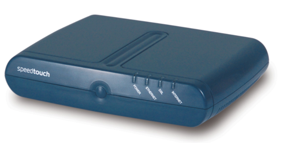
- Digital Subscriber Line (DSL) modem, which operates over a phone line, but provides speeds of up to 1.5 Mbps
- Cable modem, which operates over a coaxial cable, and provides speeds of up to 10 Mbps
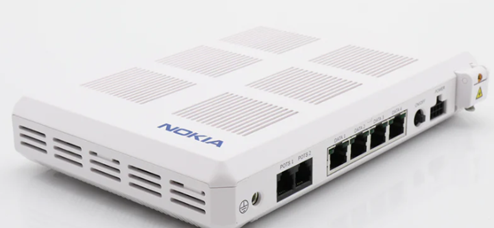
- Fiber optic cable modem, which operates over a fiber optic cable, and provides speeds of up to 1 Gbps. The fiber optic cable modem is also known as an Optical Network Terminal or ONT. Many service providers use ONTs to deliver both internet and phone lines over the same fiber optic cable.
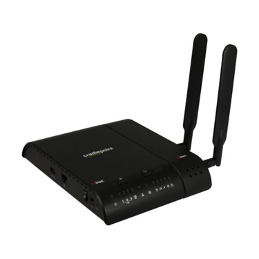
- Cellular modem, which connects to a cellular network. The speed could vary with the cellular network but could be up to 100 Mbps. The most common brand is Cradlepoint.
The next device is a firewall. A firewall monitors and filters traffic on a network.
A firewall sits between the internet (WAN) and the local network (LAN). A firewall could also sit between different segments of a LAN. For example, a firewall could sit between a group of servers and the remainder of the network.
A firewall could be hardware-based or software-based. A firewall could be a component of a larger network device such as a router. In a large organization where a great deal of traffic passes through the network, a large, hardware-based firewall must be installed. Firewalls are rated based on the volume of traffic that they can handle. Of course, more complicated configurations can reduce the amount of traffic that a firewall can handle. If the firewall must evaluate ten rules per packet, it will operate faster than if it must evaluate one-hundred rules per packet.
Common firewall brands include
- SonicWall
- Cisco ASA (Adaptive Security Appliance)
- FortiGate
- Cisco Meraki MX
Configuration of a firewall may be
- Through a console (requiring special commands)
- Through a web-based GUI or software-based GUI
- Automatically through the cloud, which is useful for organizations that deploy dozens, hundreds, or thousands of devices
An organization may select a firewall brand based on their existing network infrastructure. For example, if the customer uses Cisco switches and routers in their network, they may choose to install Cisco ASA firewalls as well.
There are four components to a firewall configuration
- ACL or Access Control List. The Access Control List is a set of rules for what traffic is permitted to pass and what traffic is not permitted. There are many types of rules, based on
- Source IP address. Where is the traffic coming from? The source IP address could be on the LAN or on the WAN. It could be a specific IP address or a range of addresses.
- Destination IP address. Where is the traffic going? The destination IP address could be on the LAN or on the WAN. It could be a specific IP address or a range of addresses.
- Source Port Number. What is the port number of the source traffic? The source port could be on the LAN or on the WAN. It could be a specific port or a range of ports.
- Destination Port Number. What is the port number of the destination traffic? The destination port could be on the LAN or on the WAN. It could be a specific port or a range of ports.
- Username. Access Control Lists can be user-based. Permissions can be granted or denied to specific users based on their needs in the organization. For example, guests can be permitted to access only the internet and not resources such as remote desktop or SQL servers.
- Rules can be specific or could combine a combination of parameters
- For example, a rule could say ‘Allow traffic from 10.1.1.1, port 5 to the range of IPs 192.168.3.0 to 192.168.3.255’. All traffic received from 10.1.1.1 port 5 will be permitted to access destinations in the range of 192.168.3.0 to 192.168.3.255. Traffic from other source IP addresses and/or ports will be rejected. Traffic from 10.1.1.1 to destinations outside of 192.168.3.0 and 192.168.3.255 will be rejected.
- Always Allow. An Always Allow rule allows all traffic matching a rule. For example, “always allow traffic from the source IP 10.1.1.1”. All traffic from 10.1.1.1 will be permitted regardless of the port number or destination.
- Always Deny. An Always Deny rule denies all traffic matching a rule. For example, “always deny traffic from the source IP 10.1.1.1”. All traffic from 10.1.1.1 will be denied regardless of the port number or destination.
- For example, a rule could say ‘Allow traffic from 10.1.1.1, port 5 to the range of IPs 192.168.3.0 to 192.168.3.255’. All traffic received from 10.1.1.1 port 5 will be permitted to access destinations in the range of 192.168.3.0 to 192.168.3.255. Traffic from other source IP addresses and/or ports will be rejected. Traffic from 10.1.1.1 to destinations outside of 192.168.3.0 and 192.168.3.255 will be rejected.
- Order of Operations
- A firewall could have dozens or thousands of rules. The rules are ranked in order of priority.
- When the firewall receives a piece of traffic, it starts checking the rules in order until it finds one that matches the traffic’s source and destination. It then applies that rule to the traffic.
- The firewall will only apply one rule to a piece of traffic. Once that rule is applied, the firewall stops checking additional rules.
- It is important to put the rules in logical order so that traffic is not accidentally accepted or rejected. When a firewall receives a piece of traffic that does not match any rules, it will either allow or reject the traffic based on its configuration.
- Many firewalls are preconfigured with two default rules
- Always allow traffic with a source inside the network (LAN)
- Always reject traffic with a source outside the network (WAN)
- Always allow traffic with a source inside the network (LAN)
- The two default rules should be put at the bottom of the list.
- The first rule (allowing all traffic from inside the LAN) is dangerous because users cannot be trusted to access only safe resources on the internet. It should be modified (broken down) into two rules.
- Always allow traffic with a
- Source inside the network (LAN)
- Destination outside the network (WAN)
- Limited to specific ports outside the network (port 80, port 443, port 3306, etc.). The specific ports should be based on resources that users need to access.
- Source inside the network (LAN)
- Always deny traffic
- Source inside the network (LAN)
- Destination outside the network (WAN)
- This rule applies second; any traffic not matching the previous rule will be denied
- Source inside the network (LAN)
- Always allow traffic with a
- The first rule (allowing all traffic from inside the LAN) is dangerous because users cannot be trusted to access only safe resources on the internet. It should be modified (broken down) into two rules.
- A firewall could have dozens or thousands of rules. The rules are ranked in order of priority.
- Source IP address. Where is the traffic coming from? The source IP address could be on the LAN or on the WAN. It could be a specific IP address or a range of addresses.
- Application-Based vs Network-Based
- An application-based firewall will analyse traffic on a deeper level than a network-based firewall
- The network-based firewall looks at traffic source and destination IP addresses, but the application-based firewall also looks at its contents
- The application-based firewall looks at the content of each packet before applying a rule.
- An analogy is a person who is screening mail. A network-based firewall would look at the to and from addresses on the envelope before deciding whether to forward the mail. An application-based firewall would open each envelope and look at the contents before deciding whether to forward the mail.
- Application-based firewalls can slow down traffic because they are analyzing the contents of each packet, which takes longer.
- An application-based firewall will analyse traffic on a deeper level than a network-based firewall
- Stateful vs Stateless
- Consider that almost all traffic on the internet is two-way traffic. When a user downloads a file from the internet, that file download is two-way. The downloader’s computer first makes a request to the server hosting the file (the sender). The sender’s computer breaks the file into packets and sends them one at a time. Each time the downloader’s computer receives a packet, it acknowledges receipt by sending a message. This is known as a connection (from TCP/IP).
- One party is responsible for originating each connection. In this case, the person who downloaded the file originated the connection (the person who is inside the network).
- A stateless firewall applies rules based only on the source and destination IP addresses and ports of the packets, but a stateful firewall will identify which party originated the connection (whether that party was inside the network or outside), and then block or allow it based on the source. A packet that is normally permitted or denied by an ACL may be denied or permitted by a stateful firewall.
- A stateful firewall requires additional hardware to process the decision making.
- Consider that almost all traffic on the internet is two-way traffic. When a user downloads a file from the internet, that file download is two-way. The downloader’s computer first makes a request to the server hosting the file (the sender). The sender’s computer breaks the file into packets and sends them one at a time. Each time the downloader’s computer receives a packet, it acknowledges receipt by sending a message. This is known as a connection (from TCP/IP).
- Implicit Deny
- As mentioned previously, a firewall lists its rules in order and applies the first rule that matches the traffic
- If the traffic does not match any rule, the firewall should deny it
- This is known as “implicit deny”
- The last rule in the list should be to deny all traffic.
- As mentioned previously, a firewall lists its rules in order and applies the first rule that matches the traffic
Cloud-Based Firewalls
Newer firewalls such as FortiGate’s and Cisco Meraki MX Series routers connect to the cloud. The cloud allows them to
- Automatically receive firmware updates
- Automatically download and update their configuration (and allow an administrator to configure multiple devices at the same time)
- Share threat intelligence data, even across organizations. For example, if a firewall detects a threat, it can upload the data to the cloud, where it is shared by many firewalls across the organization and by firewalls belonging to other organizations.
NGFW/Layer 7 Firewall
A NGFW or Next Generation Firewall, also known as a Layer 7 Firewall, is part of the third generation of firewalls. It can perform deep packet inspection.
Why do we need a NGFW? Security threats are becoming more complicated. The traditional firewall rules block traffic to/from specific addresses and ports. That’s not good enough anymore, because bad traffic can come in disguised as good traffic. Legitimate, trusted devices can become infected and used to launch attacks. The NGFW can look inside the traffic – not just at its source or destination – to decide whether it is legitimate.
An NGFW can also verify the identity of the user sending or receiving the traffic.
Router
The second thing we need is a router. A router connects two or more networks together. A router receives packets of data (from inside and outside the network) and then decides where to forward the packets to.
A router will contain a routing table (a set of static routes), which tell it where to send data based on the subnet of its destination address. In a simple setup, a router may only have one destination to send data to.
The most common type of router security is an ACL or Access Control List. An ACL is a list of source subnets (networks) and their permitted destinations. Like a set of firewall rules, an ACL check each data packet against the ACL and apply the first rule that matches.
A rule can be “always allow” or “always deny”. For example,
- Always deny traffic from addresses in the range of 252.252.252.0 to 252.252.252.255
- Always allow traffic from 192.168.2.1
A rule can apply to one or more router interfaces and to one or both directions. Each router manufacturer may have a different scheme for configuring a router ACL, but the concept is the same.
Router antispoofing is a process to prevent fake routers from joining the network. Remember that a rogue user could connect his own router to the network and attempt to route the traffic somewhere else.
More advanced routers such as Cisco ISRs can also perform some of the following functions
- DHCP server
- DNS Server
- VoIP controller (configures Voice over IP phones automatically)
- Wireless controller (configures wireless access points automatically)
Consider an unfortunately common situation where a rogue or clumsy user connects a router to a network that already has a router. Devices on the network are already configured to communicate with the existing router and will likely ignore the new one, so not much data will flow to it. But if a rogue router is also acting as a DHCP server, then when the DHCP lease expires on any network clients, they may contact the new router for a new IP address. The rogue router will also provide a different default gateway (its own) and begin to intercept traffic.
How do we prevent rogue routers? Enforce MAC filtering and other security measures on network switches as discussed further in this section.
Does the router sit behind the firewall or does the firewall sit behind the router? Which of the below scenarios is correct? Either can be correct and network administrators have been debating this issue.
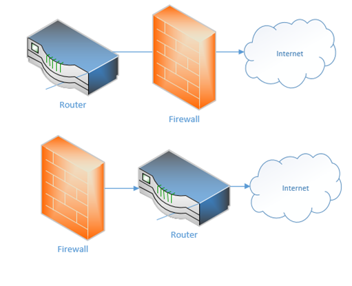
If the firewall sits between the internet and the router, it can protect the router from attacks. But if the router sits at the edge of the network, it can better communicate with external devices. Sometimes you don’t even need a separate physical router because a single device can handle all the functions – firewall, DHCP, DNS, etc.
The basic configuration of the router
- Set up a username/password, other credentials to monitor and access the router
- Identify the type of internet connection that you have, and whether the IP address is DHCP or static. Assign the correct static IP address to each WAN port if necessary
- On the LAN side, set up the scope of the LAN. What class of network will you use? Set up DHCP.
- Add routes or let the router automatically create routes.
- Create security rules
- Set up other features such as a firewall if applicable
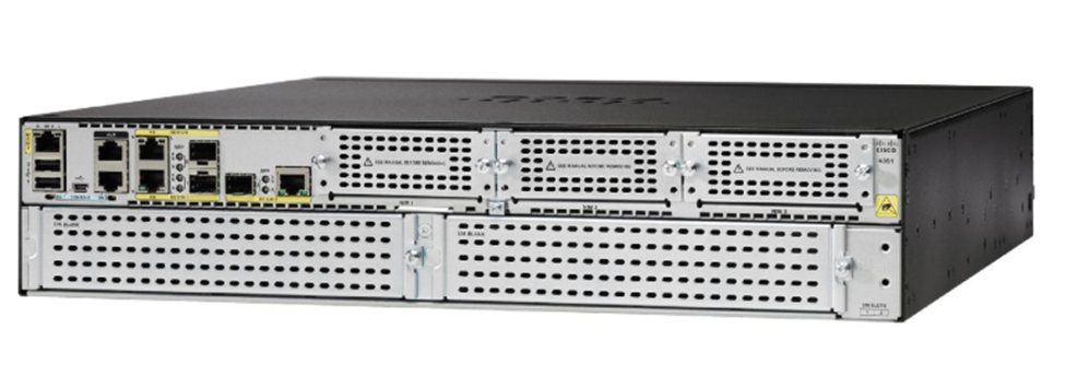
Some Cisco routers are known as Integrated Service Routers (ISR). If we look at the left side of this ISR, we can see several standard ethernet ports and a few SFP ports. These ports allow us to connect WAN connections (ethernet or fiber if we use an SFP). We can also connect USB-based cellular modems using the USB ports.
On the right side of the router, and on the bottom are panels that can be removed. We can add different modules to this router that give it additional features (such as switching, connections to more advanced internet connections, and VoIP services).
Some of the modules we can add
- An FXO card that allows us to connect analog phone lines to the router
- An FXS card that allows us to connect devices such as fax machines and other devices that require analog phone lines
- An EHWIC card that allows us to connect a T1 internet connection to the router
- A switch module that allows us to connect up to 24 ethernet-based devices directly to the router. This turns the router into a router and a switch
Switch
A switch connects multiple devices on the internal network. We install the switches after the router.
The switch keeps track of which device’s MAC address is connected to which port. Remember that each frame is addressed to a specific MAC address. When a switch receives a frame, it checks to see which port that frame’s destination MAC address is connected to, and it forwards the frame out of that port. If it doesn’t have a matching MAC address, then it sends the frame out of all the ports. This is known as flooding.
The technology inside a switch allows it to work straight out of the box – no configuration necessary. This is known as an unmanaged switch.
A more advanced switch is known as a managed switch. A managed switch is one that allows us to configure various features
- The name of the switch
- The name and description of each port
- The speed and duplex setting on each port
- VLANs
- Security settings
- Advanced routing features
We will learn more about these features later in this section.
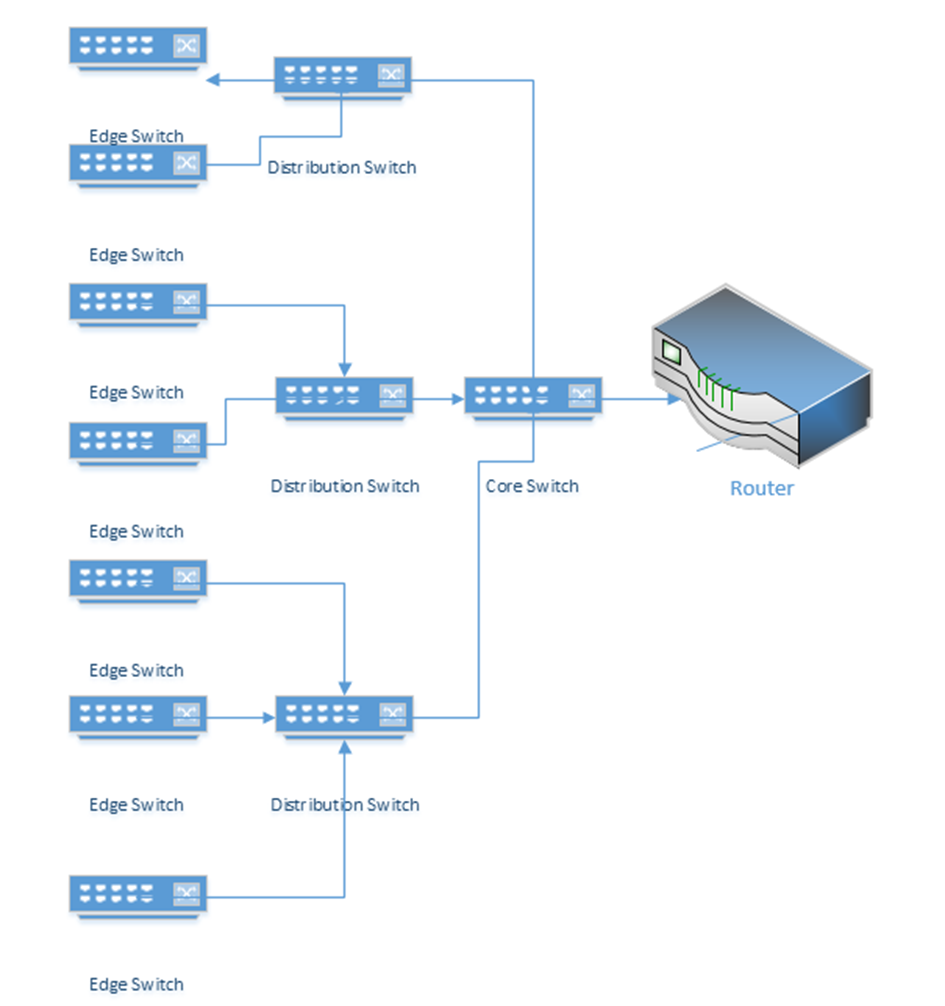
In a larger network, switches can be distributed in a hierarchy such as a three-tier or a leaf topology.
It is recommended for any switch that the following security measures are taken during initial configuration
- Create a separate, unused VLAN and shut it down
- Move all unused ports to the unused VLAN
- Shut down all unused ports
- On a physical security level, unused patch panel ports should not be physically patched into the switch. An exposed data jack can permit a user to connect a device which should not otherwise be connected.
Switches also employ MAC address filtering, which is rarely enabled by administrators in practice (but should be)
- The switch knows the MAC address of every device on every port. This data goes to a MAC address table.
- Once a network is set up, and devices are connected to a network switch, an administrator will have a list of device MAC addresses on the network.
- The administrator can configure the switch to block devices with MAC addresses different from the ones on the list.
Typical switches are “layer two” in the OSI model; that is, they can only forward data frames on the same subnet. Data outside the subnet must be forwarded to a router, even if multiple subnets are connected to the same switch. A layer three switch acts as a router in that it can forward traffic between different VLANs. Layer three switches have additional security settings, including Access Control Lists.
Switches also provide the following security features
- Spanning Tree Protocol which prevents loops between two switches. If a switch detects a loop, it shuts down one of the ports.
- Flood Guard. A flood occurs when a switch receives a large amount of traffic on a single port. Like many other electronic devices, a switch has a buffer. The buffer stores received data that the switch is waiting to process. A hacker could attempt to bypass a switch’s security measures by sending a large amount of traffic and overflow the buffer.
- Newer switches have security settings in place that can drop additional traffic or shut down the ports when flooded.
I might connect my network like the following diagram (this is common in some corporate networks)
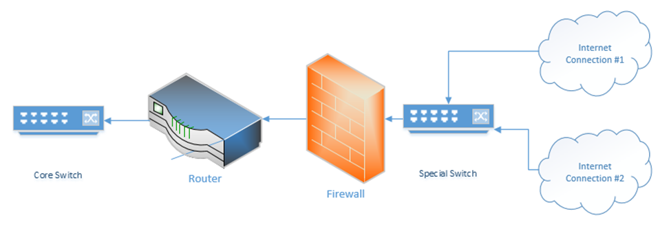
What’s up with the “special switch” that sits between the internet connections and the firewall? If I bought multiple internet connections for redundancy, but I only have one WAN port on my router or firewall, then I can connect the internet connections to a switch. The router/firewall and internet connections sit in the same subnet on the special switch. If we need to failover from one internet connection to another, we can do so through the switch.
Sometimes an ISP will provide a switch as part of their customer premises equipment. Instead of connecting to the ISP’s router or modem, you to connect to the ISPs switch. An ISP uses a switch for traffic shaping, monitoring the quality of the internet connection, delivering an ethernet WAN connection.
Hub
A hub is like a switch except that it doesn’t remember the MAC address of any device that is connected to it. When a hub receives a frame, it floods it out of all its other ports. It doesn’t think about who needs to receive it (or which ports to send it out of). This results in frequent collisions because other devices connected to the hub may be trying to send data to it. The data that the user devices send may collide with the data that the hub is sending.
Hubs can be found in older networks, but they have been largely replaced by switches. A hub performs most of the same basic functions as a switch, in other words, moving traffic between internal network devices.
Multilayer Switch
Remember that a switch works on Layer 2 to route frames between devices on the same subnet. A device isn’t supposed to be able to send traffic to a device on another subnet. What if I have multiple subnets but I don’t want to set up multiple physical switches (one for each subnet)? I can create what is called a VLAN (Virtual Local Area Network). For example, I might make one VLAN for all my computers, one VLAN for all my servers, and one VLAN for all of my security cameras.
We can assign a VLAN to each port on the switch. If devices are connected to the correct port, then the switch can then enforce the VLAN rule. In order for a device on one VLAN to talk to a device on another VLAN, it must send the traffic to the router.
A Multilayer Switch, also known as a Layer 3 Switch, can route traffic between different VLANs without the use of a router. A switch may also be able to operate on Layer 4; the transport layer. It can decide based on the
- MAC Address (in a frame)
- Protocol (in a frame)
- IP address (in a packet)
- Protocol (in a packet)
- Port number (on layer 4)
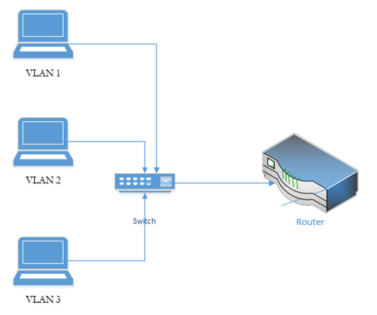
The benefit of installing a Layer 3 switch is that packets travelling from one VLAN to another do not have to travel to a router. If we used a Layer 2 switch and a router, this setup is known as a Router on a Stick, or ROAS, because the router is physically connected to a switch over one cable (on a trunk port – a trunk port is a port that has access to all the VLANs). A data packet travelling from VLAN 1 to VLAN 2 for example, travels from the top device to the switch, to the router, back to the switch and then out to the middle device.
If we replace the switch with a multilayer switch, then we don’t need the router (except to communicate with external networks). A layer 3 switch decreases latency because packets travel a shorter distance.
A Layer 4 switch takes a deeper look at the traffic before forwarding it. It can check the port number (the virtual port numbers we talked about at the beginning of the book), not the physical port number. Thus, we can configure a switch to route traffic based on its type (HTTP, FTP, etc.) and prioritize traffic based on its content, not just its destination/source.
A switch can make routing decisions based on the Layer 5, 6, or 7 content of a packet. These switches are called content switches. Common applications of a Layer 7 switch are load balancing and content delivery.
Wireless Access Point
Wireless Access Points are dispersed throughout the network and connect to a switch or multiple switches (preferably a PoE switch).
An access point sends and receives traffic over one or more “WLANs” or Wireless LANs. Each wireless LAN can be mapped to a subnet (VLAN). Each wireless network WLAN is associated with one or more SSIDs (multiple SSIDs can be associated with a single WLAN). The access point broadcasts SSIDs, which client devices can detect and connect to. An SSID can also be hidden. If an SSID is hidden, a client will be required to know its name to connect to it. In theory, hidden SSIDs can prevent hackers from connecting to the network, but SSIDs can be easily cracked.
An SSID can be configured as
- An open network, where any device can connect. This is a common setting for guest Wi-Fi.
- An encrypted network, requiring a user to enter a passphrase. There are several forms of encryption, discussed later.
- An encrypted network, authenticating through a username/password and RADIUS server/Active Directory server, or authenticating with a certificate.
An access point can be set up to
- Block connections from devices with specific MAC addresses. This is known as a blacklist.
- Allow connections only from devices with specific MAC addresses. This is known as a whitelist. We can create an open network, but only allow connections from devices with specific MAC addresses. In theory, this will work to prevent intruders without having to configure devices or provide passwords. A hacker can use a packet sniffer to intercept wireless data and then spoof the MAC address of a rogue device to match an authorized one.
Remember that every MAC address is unique and that it comes from the factory? Well, a hacker can change his! If a hacker knows the MAC address of a device that is authorized to connect, he can change his and attempt to connect.
The signal strength of an access point should at least -70 dBm everywhere that Wi-Fi is required. A weaker signal will result in frequently dropped connections.
The two main Wi-Fi frequencies are 2.4 GHz and 5 GHz. Each of these bands is subdivided into channels. The 2.4 GHz band has 11 channels, and the 5 GHz band has 54 channels.
An access point will typically broadcast on both frequencies at the same time, but only one channel per frequency at a time. The channel
- May be preconfigured by the administrator and set permanently. The access point operates only on that specific channel.
- May be set so that the access point can choose a channel and change it when necessary.
- Two nearby access points should never broadcast on the same channel at the same time. If they do, signal interference will result, and no clients will be able to connect. Consider a network in an office building, with many access points. Signals from neighboring access points will interfere and cancel each other’s signals. Signals from access points on floors above and below will also interfere. Signals from rogue devices and mobile hotspots may also interfere. An access point may receive interference from dozens of devices at the same time and must therefore be able to select a specific channel that is free of interference.
Each access point comes with a built-in antenna. You can connect an external antenna to some access points. There are many shapes and sizes of antennas, and the best antenna depends on the desired coverage area and signal strength increase required.
Special software such as AirMagnet Survey Pro or ekahau can be used to plan out wireless networks and optimize the placement of each access point. The signal strength of an access point can be affected by metal shelves, concrete walls, and other construction materials. The quantity of access points may need to be increased in densely occupied areas such as conference rooms and lecture theaters – an access point is limited to about 50 devices even if more devices are in range.
Access points can be fat or thin. A fat access point contains software to process the traffic whereas a thin access point sends data back to the controller.
Access points can be controller-based or standalone. When access points are standalone, each access point must be configured separately and operates independently. When there are multiple access points, a wireless controller is optimal. A controller
- Automatically configures access points based on a template; a controller can automatically detect and configure new access points
- Will optimize broadcast channel and power for each access point based on its traffic and signal-to-noise ratio
Cloud-based controllers and access points such as Cisco Meraki are available.
How do Wi-Fi networks detect collisions when they’re broadcasting data everywhere at the same time? In other words, if my laptop is sending data to the access point and the access point is sending data back to the laptop at the same time, the two signals will collide and cancel each other out. We use a system called the Distributed Coordination Function or DCF. If a wireless network device or access point tries to send a signal and determines that the recipient is busy, then it waits for some time before resending. Each device waits a random time to ensure that their signals do not collide a second time.
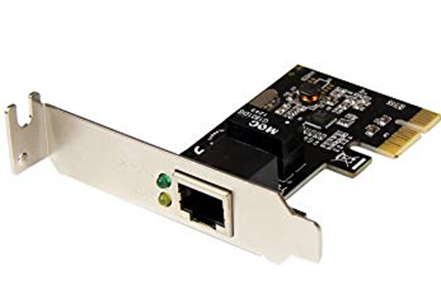
Network Interface Card (NIC)
A NIC or Network Interface Card allows a device to connect to the ethernet network. There are two types of NICs: Copper & Fiber.
- Copper NIC
- A Network Interface will operate at a particular speed, and at a particular duplex setting
- Speed
- A NIC will operate at one or more of the following speeds: 10Mbits/s 100Mbits/s, 1000Mbits/s, 10Gbit/s
- Older NICs operate at only 10Mbits/s or 100Mbits/s (known as 10/100)
- Newer NICs operate at 10/100/1000 or just 100/1000
- Only high-end NICs for servers can operate at 10Gbit/s
- A NIC will operate at one or more of the following speeds: 10Mbits/s 100Mbits/s, 1000Mbits/s, 10Gbit/s
- Duplex
- A NIC can operate as “half-duplex:” or “full-duplex”
- Half-duplex uses two pairs of wire in an ethernet cable
- Full-duplex uses all four pars of wire in the ethernet cable
- A NIC can operate as “half-duplex:” or “full-duplex”
- When a connection is established between a NIC and a Switch/Router, the two devices will negotiate a speed and duplex setting
- NIC Form Factor
- Most motherboards contain a soldered NIC chip (most common for laptops and desktops). A consumer-grade NIC will have one port.
- NICs are also available as separate PCI cards. A NIC intended for use in a server may have several ports.
- Most motherboards contain a soldered NIC chip (most common for laptops and desktops). A consumer-grade NIC will have one port.
- A Network Interface will operate at a particular speed, and at a particular duplex setting
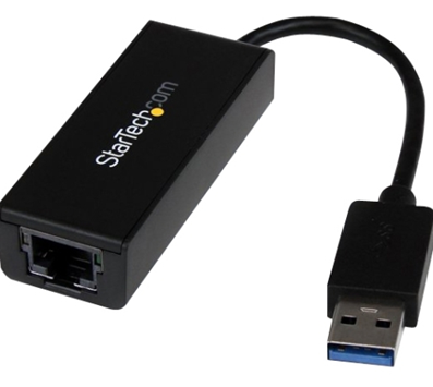
- USB to Ethernet adapter. We can create an ethernet port for a laptop or other device that doesn’t have a NIC.
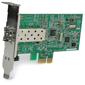
- Fiber NIC
- Like a Copper NIC, except that it accepts a fiber optic cable
- Speed
- Operates at 100Mbits/s, 1000Mbits/s, 10Gb/s
- Some can also operate at 40Gb/s or 100Gb/s
- Operates at 100Mbits/s, 1000Mbits/s, 10Gb/s
- Most commonly installed on servers and storage appliances
- The Fiber NIC will be a separate PCI card
- Like a Copper NIC, except that it accepts a fiber optic cable
Patch Panel
Now I said that we should have a switch or a bunch of switches, and we should also have a bunch of devices with NICs. What connects the NIC to the switch? I must run some copper (ethernet) cable through the building.
What do I do with it? Probably, I should terminate it to a patch panel. These panels are commonly available in 24-port and 48-port sizes. The panel fits into a standard-width network rack. Wall-mounted panels are also available.
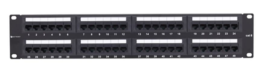
At the back of the panel are spaces to insert each wire. We should peel the STP or UTP cable and stick each of the eight wires into the appropriate slot (by color). We then use a tool called a punch-down tool to terminate the cable.
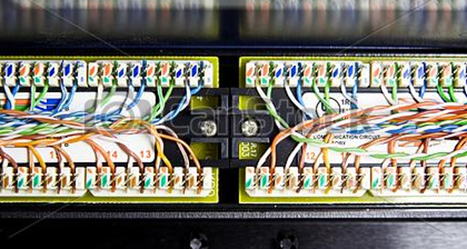
A panel costs between $50 and $600 depending on the manufacturer, number of ports, and whether it is cat5e, cat6, or cat6A.
The slots in the back of the panel have specific size. The most common size is “110”. Other sizes include 66, BIX, and Krone. Each size requires a punch-down tool with the correct shaped blade to insert the wire into the slot. The front of any patch panel looks the same, but the shape of the slots in the back will be different.
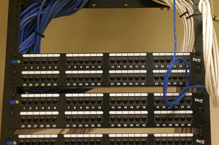
In a rack, the panels might look like the photo below
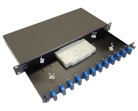
Fiber optic distribution panels can be rack-mounted or wall-mounted. Below is a rack-mounted patch panel. As you will notice, we can only terminate a fiber to a male end. The fiber panel below has female couplers at the front. We would run our fiber optic cable to the back of the panel and connect a strand to the back of each coupler.
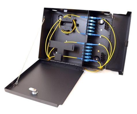
Below is an example of a wall-mount fiber optic panel
PoE
Now let’s say we wanted to connect a VoIP phone, an access point, or a surveillance camera to the switch. These devices require power. But it’s a hassle to connect the device to an ethernet cable and to a power outlet. That’s where PoE (Power Over Ethernet) comes in. PoE lets a switch power a network device.
PoE is governed by the 802.3af standard and delivers up to 15.40 W. PoE+ delivers up to 30W. Type 4 PoE delivers up to 100W. A switch capable of delivering PoE is called a PoE switch and is typically more expensive than a non-PoE switch. You must choose a switch that has enough overall capacity to power all the devices connected to it.
If you only had one or two devices that required PoE, you might connect a power injector instead of buying a PoE-capable switch. A power injector sits between the switch and the device requiring power. It takes data from the switch, adds power, and sends it to the device. It also receives data from the device and sends it to the switch.
A switch can recognize when a device (such as a VoIP phone) requires power, and when a device (such as a computer) does not. That means that it is okay to connect a computer to a PoE switch without worrying about damaging it.
PoE is becoming so powerful that many companies are using it to power things such as light fixtures and thermostats.
Software Defined Networking
Many of the things I just mentioned are going to become a thing of the past. In a software-defined network (SDN), we don’t have to worry as much about the physical infrastructure.
In a traditional network, each network device must be programmed separately, and each network device makes independent decisions about how to forward traffic. In an SDN, control of the network is separate from the physical infrastructure. Don’t take this the wrong way. The physical infrastructure isn’t going to go anywhere. We still need routers and switches and patch panels and ethernet cables.
But instead of manually programming each piece of network equipment, we create a set of rules that the software then implements across the entire network.
We can think of the SDN as a set of layers
- Application Layer – the application layer contains the rules that manage the network and forward traffic. We create rules in the application layer. The application layer can reconfigure network devices in real time.
- Control Layer – the control layer connects the application layer to the infrastructure layer. The connection between the controller and the application is called the Northbound interface. The connection between the controller and the infrastructure layer is called the Southbound interface.
The controller takes information from the application layer and translates it into the actual commands that the infrastructure layer will use to forward traffic. - Infrastructure Layer – the infrastructure layer contains the physical devices that are connected. These devices forward traffic based on information given to them by the control layer. The network’s actual capacity is limited to what the infrastructure layer can provide. The infrastructure layer may take the form of a Spine-Leaf or Three-Tier, but usually takes the form of a Spine-Leaf.
- Management Plane – the management plane contains the configuration information for the network. It is separate from the plane that contains the data being forwarded.
- Data Plane – the data plane contains the actual user data that the network is forwarding.
Traffic moving up from the infrastructure layer to the application layer is considered moving “north” while traffic moving from the application layer down to the infrastructure layer is moving “south”. Traffic moving between devices is considered moving East-West (i.e., from server to server).