
2.6 Compare and contrast common network configuration concepts
- DNS
- Address
- A
- AAA
- Mail Exchanger (MX)
- Text (TXT)
- SPAM Management
- DomainKeys Identified Mail (DKIM)
- Sender Policy Framework (SPF)
- Domain-Based Message Authentication, Reporting, and Conformance (DMARC)
- SPAM Management
- Address
- DHCP
- Leases
- Reservations
- Scope
- Virtual LAN (VLAN)
- Virtual Private Network (VPN)
Remember that there were three ways for a device to have an IP address?
The most common method is DHCP or Dynamic Host Configuration Protocol. A network administrator sets up a DHCP server (a DHCP server can be a physical computer or can be a function on a router). The administrator allocates a range of IP addresses from his network to be assigned in DHCP. For example, if the network is 192.168.0.0 to 192.168.0.255, the administrator might decide that addresses from 192.168.0.100 to 192.168.0.199 can be used by DHCP. This range is known as the DHCP Pool. An exclusion range is a range of addresses that should not be assigned via DHCP.
When a device joins a network (and doesn’t have a static IP configured), it asks for an IP address over UDP.
- It sends a message on the broadcast address asking to be assigned an IP address. If it was previously connected to the network, it might ask for the same IP address as it had before. The message contains the sender’s MAC address and is called DHCPDISCOVER. This part of the process is known as Discovery.
- Every device on the network ignores the message except for the DHCP server, which replies with an Offer, known as DHCPOFFER. The offer contains
- The IP address that the client device should acquire
- The subnet mask
- The lease time – how long the IP address will last before the device must acquire a new one
- Other details can be assigned to the device, including the DNS server address, gateway address, and NIS address
- The IP address that the client device should acquire
While the offer is pending, a DHCP server does not offer the IP address to any other device. If there are multiple DHCP servers on the network, they may each make an offer to the same device in response to the one message.
Why would we have multiple DHCP servers on the same network? We can provide different DHCP parameters for different devices. If we have VoIP phones and computers on the same network, the phones could receive DHCP from one server and the computers could receive DHCP from another.
- The client requests the IP address offered by the server by sending a Request message, known as DHCPREQUEST. All the servers find out which offer the client accepted. The servers whose offers were rejected withdraw their offers.
- The server acknowledges that it has assigned the DHCP address to the client by sending it an Acknowledgement message known as DHCPACK.
- The client configures its own network interface using the information received from the DHCP server.
A DHCP server can be configured to assign IP addresses using one (or more than one) of three schemes
- Dynamic Allocation. The server picks the first available address from the range and assigns it to the device. If I have a large Wi-Fi network such as in an airport, with thousands of different devices connecting to it each day, I will allocate DHCP addresses dynamically. Chances are that my network won’t see the same device often.
- Automatic Allocation. The server remembers which address it assigned to the device in the past. It tries to assign the device the same IP address each time, if available. If I had an office with users who bring their laptops to work, I would try to allocate the same IP address to each device. I wouldn’t make it mandatory because devices are sometimes replaced, and new devices are added all the time.
- Manual Allocation. The administrator manually programs a relationship between a MAC address and an IP address. If a device with a matching MAC address joins the network, it is automatically assigned the same IP address each time. The network will reserve this IP address and never assign it to any other device.
I would use this when I have specific devices like printers and surveillance cameras, which are better off accessible at the same address each time, and I’m not able to program a static IP address into each device (or don’t want to).
The DHCP protocol is still evolving under IPv6. It’s a lot different from IPv4
- A device can configure itself automatically with a tool called Stateless Address Autoconfiguration. How does it know what address to give itself? Under IPv6, routers are automatically sending out “advertisements” over the network, telling devices what prefix they follow. A device learns the prefix for the network that it’s on and then selects an IP address at random. Remember that the IPv6 address space is massive; the chance that a device chooses the same address as an existing device is small. Nevertheless, a device will check for conflicts. If there is one, the device selects a new address.
- One idea behind IPv6 was that any device could be reached from any device, regardless of whether it was on an internal or external network.
- One problem with IPv6 is that a mobile device can maintain the same IP address across multiple networks. This makes it easy to track. To avoid privacy concerns, mobile devices change their IP addresses often (at least every day).
- Even after a device assigns itself an IPv6 address, it might need some other data from the server, which it can obtain over DHCP.
- In a large network with multiple routers (such as the thousands of residential routers connected to an ISP’s network), a router can automatically be assigned a prefix via DHCPv6. This is known as prefix delegation. A router asks for a prefix from the DHCPv6 server. Once assigned, the ISP routers send traffic to the router with the newly assigned prefix.
In the traditional DHCPv6, a device can request an IP address from a DHCPv6 server
- The device sends a solicit message asking for an IP address
- The DHCP server replies with an advertise, offering an IP address
- The device sends a request, requesting the IP address that was offered
- The server confirms that it has assigned the IP address, with a reply
We can skip all this DHCP and assign every device a static IP address. The static address is manually assigned to the device and doesn’t change. We can create a network that uses both static and dynamic addresses.
What if I have a large, distributed network but I only have one central DHCP server? I could use a tool called a DHCP Relay. The DHCP Relay lives in the router. It listens to DHCP messages from the internal network and forwards them to an external DHCP server. It also receives DHCP messages from the external server and forwards them to requesting devices on the internal network. On a Cisco router, this is known as an IP Helper Address. It may also be called UDP Forwarding.
We must be careful to assign a static IP address
- That does not conflict with any addresses in the DHCP pool of the network. A DHCP server may assign the same IP address as a statically assigned device, which would result in a conflict.
- That is in the same subnet as the network. If our network is 192.168.0.0 to 192.168.0.255, and we assign the device an IP address of 10.0.0.1, then it won’t be able to communicate with any other device.
- That contains all the required parameters including the gateway, subnet mask, and DNS servers. A device that is missing the gateway won’t be able to communicate with devices on the outside network. A device that is missing the DNS won’t be able to look up hostnames.
DNS
Remember that a computer understands addresses in numeric format (like 8.8.8.8) and a human understands text (like google.com). How does the computer know where google.com is (i.e., the IP address of the google.com server)? We use the DNS (Domain Name Service) to convert the human-readable address into a computer-readable address.
When I try to visit google.com, my computer calls up the nearest DNS and asks it to provide information about google.com. google.com is known as a domain name or a hostname. A DNS will contain a set of records about each domain name. Those records are given to the DNS by the owner of the name. The record for the domain is called a record set. What kind of information can it provide?
- A or AAAA. The A (Address Mapping) record tells us the IPv4 address of the server that is hosting the domain name. The AAAA record tells us the IPv6 address that is hosting the domain name.
- TXT (SPF, DKIM). The TXT (Text) record tells us some text. Two common uses of TXT records
- SPF or Sender Policy Framework. Think of an e-mail like a letter. It has a “to” address and a “from” address. I could send a fake letter and use a fake “from” address because nobody can verify that the “from” address is correct. An e-mail is the same. A spammer could spoof the “from” address and make it look somebody legitimate sent the e-mail. How can we stop this?
If the legitimate sender has control over his domain name and server, he can create a Text entry called the SPF and put the IP address of his e-mail server in there. Then when we receive an e-mail from that sender, we can verify that it came from an e-mail server with an IP address matching the record.
When a recipient receives a message, he checks the IP address in the SPF belonging to the legitimate sender. If it matches the actual sender, then he knows that the e-mail is legitimate.
- DKIM or DomainKeys Identified Mail is another way to identify an e-mail’s legitimate sender. A user of DKIM creates a unique signature via public key cryptography. It’s essentially a signature that can’t be forged – it has two parts, a private key that only the sender knows, and a public key that recipients can use to verify his identity. The legitimate sender places a copy of the public key in DKIM. He uses the private key to digitally sign every e-mail he sends. When a recipient receives an e-mail, he verifies that the signature in the e-mail matches the public key in the record.
- SPF or Sender Policy Framework. Think of an e-mail like a letter. It has a “to” address and a “from” address. I could send a fake letter and use a fake “from” address because nobody can verify that the “from” address is correct. An e-mail is the same. A spammer could spoof the “from” address and make it look somebody legitimate sent the e-mail. How can we stop this?
- SRV. The SRV (Server) record tells us about the location of servers that operate specific services. The server location includes an IP address or domain name and a port number. The domain name in an SRV record must itself have an A record in its own DNS record set or else it won’t be located.
- MX. The MX (Mail Exchanger) record tells us the IP address or domain name of the mail server that receives e-mail on behalf of the domain. If my e-mail is hazim@hsmservices.ca and I host my own e-mail, then the record may point to my own server. If my e-mail is hosted by Gmail for example, my MX record may point to gmail.com.
When you send an e-mail, your e-mail program (or SMTP server) will query the MX records for each recipients’ address so that it knows where to send the message.
The domain name in an MX record must have its own record in its own record set, or else it won’t be located. - CNAME or Canonical Name points one domain name to another. The purpose of a CNAME record is to point one name to another. The CNAME record must itself have an A name record.
For example, foo.example.com can point to bar.example.com. bar.example.com must have an A record in its own record set or else it won’t be located.
When a computer receives a CNAME reply, it must then look for the corresponding A record. - NS or Name Server. The NS record tells us which DNS server is authoritative for the domain. The owner of a domain name maintains DNS records for his name on an authoritative name server. The authoritative name server has the most accurate records for that specific name. A name server can be authoritative for one or more domain names.
Since the internet is distributed, DNS servers operated by other users might copy the records from the authoritative name server and respond to queries from devices close to them. When you access a website, your computer won’t necessarily query the authoritative name server for that site. It may query a local nameserver operated by your organization or ISP. - PTR or Pointer Record. A Pointer record allows a user to perform a reverse DNS lookup. PTR Records are stored under the IP address of the server, not the domain name.
- SOA or Start of Authority Record. The SOA gives us information about which DNS is authoritative for the domain. When our domain name server wants an update to the record, it checks the SOA to determine which DNS server to check.
The SOA contains a serial number. Each time the DNS record is updated, the SOA serial number is increased by one. When a client wants to transfer its DNS record to another server, it checks the serial number first. If the server does not have the current version of the record, then the transfer is authorized. This is known as a Zone Transfer.
A Reverse DNS lookup is when we have an IP address and want to know which domain name it belongs to. An IP address may belong to multiple domain names. The PTR record is used for the Reverse DNS lookup.
We can obtain the domain name corresponding to an IP address by querying the domain name in-addr.arpa. If we want to know the domain name for the IP address 1.2.3.4, we will query the name:
4.3.2.1.in-addr.arpa
Notice that we prepended the IP address in reverse to the front of the in-addr.arpa domain name. This is opposed to the Forward DNS lookup that we come to expect.
To provide load balancing and redundancy, each DNS record can contain multiple entries. We can give each entry a different priority. For example, we might have multiple servers to handle our e-mail or website hosting. In case one server is down or can’t handle the traffic, then the other servers can run.
An internal DNS is one that is operated by an organization for use on its internal network. A network might have devices that are accessible internally such as servers, switches, and printers. Each device is assigned a unique hostname on the network. The internal DNS server provides users with DNS records corresponding to these internal devices. A user may need to access both internal devices and external hosts. Therefore, the user may need to program his computer to query both an internal DNS server and an external DNS server. The external DNS provides information about hosts that are available to the public (on the internet). It is possible for an internal DNS to also be an external DNS.
An organization may choose to host its DNS with a third party. Examples of third-party DNS include Amazon (AWS) Route 53 and Cloudflare. A third-party DNS is scalable and can provide inquiries to many users at the same time. In addition, a third-party DNS is centrally located so that updates to the DNS propagate across the internet quickly.
The hierarchy of a DNS starts at the root domain name server. There are only 13 root servers. The servers provide responses to the “root” domain (i.e. .com, .net, .org). When a computer looks up a domain name, it starts at the right side and looks up the authoritative name server for the root.
Then the computer checks the authoritative server, which is maintained by the owner of the domain name. Below the authoritative server are servers operated by national internet service providers. They aggregate DNS records from the different authoritative servers. Below them are servers operated by local ISPs. Below them are servers operated by organizations for local networks.
When we query a DNS server, we might start at the local level. If the local server doesn’t have an answer, we check at the next level. If it doesn’t have an answer, we continue working our way to the top until we reach the authoritative server.
In a recursive DNS search, your computer makes a query with the DNS server. If the DNS server doesn’t have an answer, it checks the next higher up server (and up and up) until it finds an answer. It might cache the answer in case other computers request the same DNS record.
In an iterative DNS search, your computer makes a request from the DNS server. If the DNS server doesn’t have an answer, it gives your computer the IP address of the higher up server. Your computer then makes the query with the higher up server. If it doesn’t receive an answer, it continues to make queries up the DNS chain until it reaches the authoritative server.
Each DNS record has a TTL or Time to Live. This is a number that tells the non-authoritative DNS servers the length of time (in seconds) until a record expires. For example, if a TTL is 3600, then the DNS record expires after one hour. If my local DNS server obtains authoritative DNS records from google.com’s DNS, and the TTL is one hour, then it should check with the google DNS again for updated records after one hour. The TTL is set by the authoritative name server. The process of maintaining local DNS records is called DNS caching.
If we make the TTL long, then any changes will take a long time to propagate across the entire internet. If we make the TTL short, then changes will propagate quickly, but our DNS server will experience more queries because lower-level name servers are requesting updates more frequently.
I mentioned VLANs and switches earlier, but now let’s take a closer look. We already said that if we have a single physical network with an IP address range, we can break it up into multiple subnets. And we can assign different types of devices to different subnets (for example, computers, phones, security cameras, etc.).
When we have different devices with different subnets connected to the same physical switch, we need to make sure that their traffic stays separate.
We could create a VLAN or Virtual Local Area Network. We could assign each switch port to a single VLAN. Any device connected to that port belongs to that particular port’s VLAN.
A host such as a phone, computer, or switch will belong to a single VLAN.
Simple switches do not support VLANs. These are commonly known as unmanaged switches. On an unmanaged switch, all the ports belong to VLAN 1 and there is no option to add additional VLANs.
What if we have a large network with multiple switches? Let’s say we have one core switch and ten edge switches. And let’s say we have ten VLANs. If I want a device on VLAN 1 switch 1 to be able to talk to a device on VLAN 1 switch 2, then I need to choose a port on the core switch and a port on switch 1, set each of them to VLAN 1, and connect them with a patch cable. I could do this for the other nine VLANs and the other nine switches, but then I’d run out of switch ports. My core switch might only have 48 ports. Clearly this is not a good solution.
How can we transport traffic from multiple VLANs between the same set of switch ports? We can use a trunk port. We choose a port on the core switch, and a port on switch one, and connect them with a patch cable. Then we configure them as trunk ports. We tell the switch which VLANs are permitted to transport their traffic through that trunk port.
A Trunk port carries traffic for multiple VLANs. Each frame is tagged with its VLAN. Ports that are not trunk ports are known as Access ports. An Access port belongs to a single VLAN. The switch assumes that traffic through that port belongs to the VLAN assigned to the port. The standard for VLANs is called 802.1Q.
This brings us to our next point: Tagging and Untagging ports. An access port is known as an untagging port or untagged port because it strips the VLAN tags off any traffic it receives and because traffic passes through the port untagged. A trunk port is known as a tagging port or a tagged port because it adds VLAN tags to any traffic it receives, and because traffic passes through the port tagged.
Now we have three scenarios for traffic flow within the switches
- Traffic moving between two devices on the same VLAN and on the same switch. This traffic moves from one access port on the switch to another access port on the same switch.
- The switch receives the frame
- The switch realizes that the destination device is directly connected to the switch
- The switch realizes that the source port and the destination port are assigned to the same VLAN
- The switch forwards the traffic out of the destination port
- The switch receives the frame
- Traffic moving between two devices on the same VLAN but connected to different switches.
- The switch receives the frame
- The switch realizes that the destination device is connected to another switch through a trunk port
- The switch tags the frame with the VLAN ID of the port it was received on
- The switch forwards the frame through its trunk port to the appropriate switch
- The receiving switch receives the tagged frame
- The receiving switch realizes that the destination is directly connected to it
- The receiving switch removes the VLAN ID from the frame and sends the frame to the correct destination
- The switch receives the frame
- Traffic moving between two devices on a different VLAN
- The switch will forward the traffic to the router and the router will decide whether to forward the traffic back to the switch
- If the switch is a Layer 3 switch, it may apply its own rules to forward the traffic
- The switch will forward the traffic to the router and the router will decide whether to forward the traffic back to the switch
It is important that we configure the same VLANs on every switch. If VLAN one on switch one is VLAN two on switch two, it takes little to imagine what kind of problems that would cause.
Every port can be assigned to one VLAN only. There is one exception. Access ports on a Cisco switch can be configured with two VLANs. Why? In a large organization using VoIP, the VoIP phones are connected on one VLAN and the computers are connected on another VLAN.
This is known as IP Passthrough because the phone passes the computer’s traffic through to the switch. The main advantage is that the organization only requires one cable per user. The Cisco switch knows how to separate VoIP and user traffic.
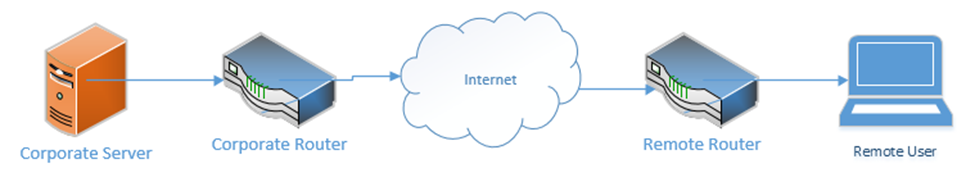
A VPN is a Virtual Private Network. It allows a remote user (working from home, a hotel, a hotspot, etc.) to connect to a corporate network through a tunnel. Essentially, the traffic from the user’s computer is packaged and sent through a tunnel to the corporate network. If the user attempts to access a website while connected to the VPN, that request is first sent to the corporate network, which forwards the request to the website. The corporate network also takes the traffic that it received from the website and sends it back to the user through the VPN. Therefore, traffic received from the user appears to be coming from the corporate network, regardless of the user’s location.
A VPN “tricks” the user’s computer into thinking that it is on the corporate network so that the user can access resources such as internal applications, shared drives, and printers.
A VPN concentrator is a device that collects and manages VPN connections from multiple users and passes their traffic to the LAN. It could be hardware-based or software-based. The VPN concentrator functionality can be incorporated into another network device such as a router.
VPN functionality is incorporated into devices such as
- Cisco Routers
- Cisco ASAs
- FortiGate’s
- SonicWall’s
- Cisco Meraki Routers
Remote users can use software to establish VPNs (such as Windows VPN or Cisco AnyConnect) or can install hardware-based VPN appliances such as a Meraki Z3.
Features of the VPN concentrator include
- Remote Access vs. Site-to-Site. A Remote Access VPN allows users to connect back to a corporate network, typically through their computer. A Site-to-Site VPN allows two offices to connect to each other and pretend like they are part of the same physical network. A Site-to-Site VPN typically applies to the site’s router and not to individual devices on the network.
- The performance on a VPN is affected by the quality of the user’s internet connection, by the quality of the corporate network’s internet connection, by the number of active users, and by the type of resources being accessed.
- When there are multiple sites that need to be connected, a site-to-site VPN should be replaced by a WAN
- The performance on a VPN is affected by the quality of the user’s internet connection, by the quality of the corporate network’s internet connection, by the number of active users, and by the type of resources being accessed.
- IPsec. IPsec is a set of protocols that allow hosts to exchange packets securely. IPsec has several modes of operation, including
- Tunnel Mode. The Tunnel Mode encrypts the source, destination, and contents of every packet. Essentially, it establishes a secure tunnel between two network devices where data can travel securely. The devices that are establishing the tunnel are not necessarily the devices that are creating the traffic. For example, a router could be sending traffic on behalf of a server inside the network. An outsider will not be able to examine the source, destination, or contents of any traffic.
- Transport Mode. The Transport Mode only encrypts the contents of the packet. It does not encrypt the source or destination. An outsider will be able to examine the source and destination. Transport Mode is established by the two network devices who are communicating, and not by the routers on the edges of the network.
- SA. An SA, or Security Association is an algorithm and key that are used to encrypt traffic in an IPsec tunnel. Each direction of communication requires a separate SA. Therefore, most IPsec tunnels will require two SAs.
- There are four methods of connecting a tunnel. Consider that two computers (each inside a separate network and behind a router) would like to communicate securely across the internet. How can an IPsec tunnel be established?
- Machine-to-Machine. Two computers (or smartphones) establish a tunnel and communicate. This is not practical because each computer will expend a substantial amount of computing power encrypting and decrypting the IPsec traffic.
- Router-to-Router. It is assumed that the connection between the computer and the router (on the internal network) is secure. The routers establish an IPsec tunnel. The computers no longer encrypt traffic between themselves and the routers. The routers encrypt all traffic between themselves.
- Machine-to-Machine and Router-to-Router. This combines the previous two scenarios. Each machine establishes an IPsec tunnel with the router on its network, and the routers establish an IPsec tunnel between themselves.
- Remote User. A remote user connects to a router through an IPsec tunnel, and then establishes a secondary IPsec tunnel to connect to a device deeper in the network.
- Machine-to-Machine. Two computers (or smartphones) establish a tunnel and communicate. This is not practical because each computer will expend a substantial amount of computing power encrypting and decrypting the IPsec traffic.
- Tunnel Mode. The Tunnel Mode encrypts the source, destination, and contents of every packet. Essentially, it establishes a secure tunnel between two network devices where data can travel securely. The devices that are establishing the tunnel are not necessarily the devices that are creating the traffic. For example, a router could be sending traffic on behalf of a server inside the network. An outsider will not be able to examine the source, destination, or contents of any traffic.
- Tunnel Mode Encryption. The tunnel mode is the method for encrypting the traffic. Consider that two routers have created an IPsec tunnel and that behind each router is a computer that wants to communicate. What is the order of operations?
- The computer generates some data and places it in a packet.
- The computer puts the address of the remote computer in the header of the packet (or the address of the network that it is sending it to, when the network employs NAT – more on this later).
- The computer sends the packet to the router (through the switch)
- The router encrypts this packet, including the headers
- The router encapsulates this packet inside a larger packet and adds the recipient’s router address to the header
- The router sends the packet to the destination router
- The destination router removes the outer header, decrypts the packet, and forwards it to the computer inside its network
- Neither computer is aware of the existence of the IPsec tunnel
- Tunnel encryption works through the following security protocols
- AH. Authentication Header. When AH is used, the original IP header (created by the computer that generated the data) is visible to outsiders, but the contents are protected. AH protects the integrity of the data. That is, the recipient can be sure that the sender listed on the packet is in fact the true sender.
- ESP. Encapsulating Security Payload. ESP encrypts the contents of the data, but it does not guarantee integrity.
- It is recommended to use both AH and ESP, thereby providing privacy and integrity.
- AH. Authentication Header. When AH is used, the original IP header (created by the computer that generated the data) is visible to outsiders, but the contents are protected. AH protects the integrity of the data. That is, the recipient can be sure that the sender listed on the packet is in fact the true sender.
- IPsec algorithms
- IPsec is a framework for exchanging data, but the contents of the framework vary from vendor to vendor and network to network. Just like there can be many different models of vehicles on a road, all following the same traffic rules, there can be many different types of algorithms to exchange data within a tunnel.
- Many different encryption algorithms can be used. This flexibility allows an algorithm to be replaced when it is discovered to be weak.
- Methods include
- Diffie-Hellman key exchange with public key signing
- MD5 and SHA-1 hashing algorithms to ensure data integrity
- Diffie-Hellman key exchange with public key signing
- IPsec is a framework for exchanging data, but the contents of the framework vary from vendor to vendor and network to network. Just like there can be many different models of vehicles on a road, all following the same traffic rules, there can be many different types of algorithms to exchange data within a tunnel.
- IPv4 vs IPv6. IPsec is integrated into all IPv6 packets by default, but not IPv4 packets. When IPv4 was designed, security was not a primary consideration. As the internet grew, the design of IPv6 required security to be integrated into all communications. A device can use IPv6 and not activate the IPsec feature however.
- The computer generates some data and places it in a packet.
- Split Tunnel vs. Full Tunnel
- In a Full Tunnel VPN, all traffic is routed through the VPN, but in a Split Tunnel VPN, only specific traffic is routed through the VPN.
- The advantage of a split tunnel is that it reduces bottlenecks. Consider a corporate user working from home. The user needs to access network resources such as a shared drive and corporate finance applications. This traffic must go over the VPN. The user is also watching YouTube videos in the background. There is no reason to route YouTube videos over the corporate network (requiring encryption on both sides). YouTube traffic can travel over the user’s home internet connection.
- In a Full Tunnel VPN, all traffic is routed through the VPN, but in a Split Tunnel VPN, only specific traffic is routed through the VPN.
- TLS. In addition to providing internet security, Transport Layer Security is an alternative to IPsec VPN. A TLS VPN is useful when the network uses NAT.
- Always-On VPN. An Always-On VPN is just like it sounds. It is a VPN that is always on. Typically, an Always-On VPN is part of a hardware appliance, but it could also be software-based. When the VPN detects an active internet connection, it automatically attempts to re-establish the VPN.
For security purposes, an Always-On VPN can block traffic from travelling over the internet when the VPN is not running. This would prevent a user from inadvertently disclosing his true location to websites that shouldn’t know it.