
1.1 Compare and contrast the Open Systems Interconnection (OSI) model layers and encapsulation concepts
- OSI Model
- Layer 1 – Physical
- Layer 2 – Data Link
- Layer 3 – Network
- Layer 4 – Transport
- Layer 5 – Session
- Layer 6 – Presentation
- Layer 7 – Application
- Data encapsulation and decapsulation within the OSI model context
- Ethernet Header
- Internet Protocol (IP) Header
- Transmission Control Protocol (TCP) / User Datagram Protocol (UDP) headers
- TCP Flags
- Payload
- Maximum Transmission Unit (MTU)
In my previous book, I had an introduction about how networks function, but now that the order of the material has changed, we are going to jump right in. I will introduce background material as needed.
The question we want to ask is: how does data on a network (or on the Internet) get from one point to another? How is it that when you plug a computer into an ethernet jack or connect to the Wi-Fi in a building, things just work (usually)? How do devices understand each other?
Well, manufacturers create devices according to established standards. Devices communicate with each other based on specific protocols (languages) that are defined by the international community. If you get into the business of making ethernet adapters, patch panels, fiber optic cables, switches, routers, etc., you will also have to follow those standards and protocols so that your devices can communicate with all the existing devices.
To create these standards and protocols, we had to create a model of the network. The OSI (Open Systems Interconnection) model is the single most important concept you will need to know (to pass the exam). OSI is just a concept.
There are seven layers:
- Layer 1 – Physical
- Layer 2 – Data Link
- Layer 3 – Network
- Layer 4 – Transport
- Layer 5 – Session
- Layer 6 – Presentation
- Layer 7 – Application
We are going to see some examples of communications that allows this model to make sense. But each layer carries data for the layers below it. Or in other words, each layer packages (encapsulates) the data from the layer below it. So, a device or program on the Application layer creates content and addresses it to a device on the Application layer at the other side. It gives this content to a device Presentation layer, which packages it, addresses it to the device in the Presentation layer on the other side, and sends it a device on the Session layer. This goes on until we get to the Physical layer.
When the data is received by the Physical layer on the other side, it is unpackaged and sent up the devices on each layer until it is received by the Application layer.
We need to understand the layers so that
- We can design a network and make sure that all the devices are connected and that they can communicate with each other properly
- We can identify which layer is affected when something goes wrong. This way, we can properly troubleshoot the software or configuration that is causing the issue
- We can start troubleshooting at the bottom layer and work our way up, or start at the top layer and work our way down, or figure out what is the highest layer that is working and then troubleshoot the next layer above it
Let’s look at an example. You want to send an e-mail. The Layer 7, Application Layer is the software that a user sees (Microsoft Word, Google Chrome, etc.). You type up the e-mail in Microsoft Outlook and send it off. But what is really happening? You only saw the seventh layer.
Well, Layer 6 is the Presentation Layer. It takes the data from Layer 7 and makes sure that the Application layer of the recipient can understand it. What if the recipient’s computer has a Mac or Unix operating system? What if the user doesn’t use HTML to display e-mails? What if the user’s computer is in a different language?
Idea: If you type up a document in Microsoft Word and then open it in Notepad, it will look like gibberish. Why? Because Microsoft Word has its own internal language that keeps track of things like fonts, formatting, layout, highlights, etc.. This language is useless to humans. Humans just want to see the properly formatted Word document or e-mail. So, the Presentation layer takes this gibberish that the computer understands and converts it into something that a human understands. If you open the same e-mail on your phone, or tablet, or 24” monitor, it will look different. The Presentation Layer on each device understands the capabilities of that device and translates the gibberish into a format that is suitable for its Application layer.
Layer 5 is the Session Layer. What is a Session? A Session is when two devices agree to communicate with each other for a period. When you send the e-mail, your computer calls up the receiving computer and says, “hey, I want to send you an e-mail”. The two computers use the session to exchange data and keep it open until one or both decide to close it. Technically (as we will find out layer), your computer wouldn’t directly contact the recipient’s computer. It would call up the e-mail server of its own service provider and send the e-mail there. That e-mail server would call the e-mail server of the recipient and send the e-mail there. The receiving e-mail server would call up the recipient’s device and further transport the e-mail. We just tried to make it simple for this example.
Layer 4 is the Transport Layer. Layer 4 takes the data from the Session Layer and packages it or breaks it into pieces. So, it might cut up your e-mail into chunks, give each one a number, and send each chunk separately to the recipient. The recipient has already agreed to receive these chunks because it has an established session. The Transport Layer on the other side would put them back together in the correct order. If some of those chunks don’t show up, the sending Transport Layer can send them again. The Transport Layer also puts the IP address of the recipient on each chunk. Later, we are going to look more specifically at a transport protocol known as TCP/IP.
Layer 3 is the Network Layer. Say you are in New York City and you are sending an e-mail to a device in Los Angeles. Layer 4 put the IP address of the recipient on each “chunk”. How does the data get to the destination? Throughout the internet are many routers and many cables. So, there are many pathways for data to get from NYC to LA. The router in your office looks at the destination IP address and decides about the next router to send the e-mail to (probably the main NYC router for your ISP). That router receives the data and makes its own decision sending it to a router in California. A main router in California sends the data to a router in LA. Finally, a router in LA forwards that e-mail to the recipient’s office router. Routers have algorithms that make these decisions efficient (as we will learn about later).
In the Layer 3, we call each “chunk” of data a packet. We will find out later that a packet has a very specific format so that routers can understand them. The size of the packet is known as the Maximum Transmission Unit. The sender and recipient agree on the largest size of packet that they can handle.
You can think of this layer like the mail. If you send a letter from NYC to LA, a mailman isn’t going to pick up the letter and drive straight to LA with it. Instead, that letter will go to the local NYC post office no matter the destination (just like your local office router must process all of the outgoing data no matter the destination). The local post office sorts mail going to California and ships them off to a main post office in California. That post office sorts the mail going to LA and ships them to the main LA post office. The main LA post office sorts the mail into routes for trucks and letter carriers, and those trucks and letter carriers deliver your letter to the recipient.
Layer 2 is the Data Link Layer. Layer 2 allows two directly devices to communicate. Every network device has a unique address called a MAC address. This address is burned in to the device from the factory and is unique regardless of the manufacturer. Layer 2 uses MAC addresses to forward traffic.
Remember those chunks called packets? Well, your computer doesn’t send packets. It creates the packet and puts the destination IP address on it, but your computer doesn’t know how to get it to California. So, the destination IP address is kind of useless to your computer.
Instead, your computer thinks about the next destination of the packet. It might be the same office, an office across the street, or an office in another country. As we will find out later, your computer just needs to think about whether the destination is within the office or outside the office (or in other words, whether it is behind the router or past the router).
Your computer finds out the MAC address of the packet’s destination. Then the computer packages this packet into a frame and adds the destination MAC address. If the destination is within your office, your computer puts the destination MAC address of the actual recipient. If the destination is somewhere else, your computer won’t be able to figure out the destination MAC address, so it puts the destination MAC address of the router as the recipient. The router receives this frame and removes the packet. Then it figures out the MAC address of the next destination (probably the next router). It puts the packet into a new frame with a new MAC address as the destination.
Your computer might be connected directly to your office router, but most likely it will connect to a switch. The switch understands and forwards frames based on the MAC address. We will find out more about how switches work later. When you send a frame to a device within your office, the switch can deliver that frame without having to talk to the router. When you send a frame addressed to the router (i.e. a frame containing a packet that has a destination outside of your office), the switch delivers that frame to the router.
In the case of our e-mail example, your computer encapsulates the packets containing pieces of your e-mail into frames. It puts the MAC address of your office router as the destination. The office switch delivers those frames to the router. The router removes the packet from the frame. The router finds the MAC address of the next router and packages the packet into a new frame. It puts the MAC address of the next router into the destination field on the new frame and sends it along. This process continues until the frame is finally delivered to the destination.
Layer One is the Physical Layer. It is the actual transmission layer and contains the wiring. Layer One also deals with directly connected devices. When your computer tries to send data to the switch, your computer and the switch must agree on a speed. What if your computer or the switch can’t handle a speed that is too high? Thus, two directly connected devices must agree on the speed to use on the line. If the line supports only a one-way transmission, they must also agree who will talk and who will listen at each time.
Now let’s think about the router in the receiving office. The Physical Layer receives the data (0’s and 1’s as an electronic or fiber transmission). That data is eventually recorded into a frame on Layer Two. The router’s Layer Two receives the frame. The router’s Layer Three technology removes the packet from the frame and figures out the destination MAC address of the device in the office that is entitled to it. It repackages the packet into a frame with the new destination MAC address and forwards the frame.
The switch in the office receives the frame and forwards it to the correct computer. The receiving computer removes the packet from the frame and sends it to the Transport Layer. The Transport Layer waits until all the associated packets are received and reassembles them. It also asks for missing packets to be resent (if any). The Transport Layer sends this assembled data to the Session Layer. The Session Layer sends the data to the Presentation Layer, which understands that the data is an e-mail. The Presentation Layer thinks about the best way to translate the content for the Application Layer. The Application Layer displays the e-mail in the recipient’s web browser or e-mail application.
When the router puts a packet into a frame, it is called encapsulation. When a router removes a packet from a frame, it is called deencapsulation. We are going to use those words more often throughout the book.
A frame has the following format
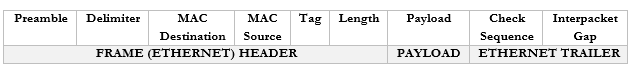
You don’t need to worry too much about these now but
- Preamble. This lets the devices know that this is an Ethernet frame. It is a bunch of 0’s and 1’s that let the two devices sync so that they don’t miss or misinterpret any of the following data and looks like this – 10101010 10101010 10101010 10101010 10101010 10101010 10101010 10101011.
- Delimiter. Basically, just a space to say “pay attention, the preamble is finished, and the real data is starting. We need the delimiter because the receiving device may have missed a portion of the preamble and won’t know how long until it ends.
- MAC Destination. The MAC address of the destination device.
- MAC Source. The MAC address of the source device.
- Tag. The tag is optional but tells us some information about the frame and its priority.
- Length. The length of the frame.
- Payload. The actual data we are sending.
- Check Sequence. A check digit that is mathematically computed from the frame data. It is used by the recipient to verify that the data was received correctly.
- Interpacket Gap. A space we make before sending the next frame.
Remember that the router strips the headers from the frame to look at just the Payload. It can add new headers if necessary. Well, the Payload is actually a Packet with its own Header and Payload.
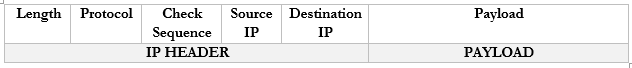
Notice that in the IP world, we only have headers and no trailer.
You don’t need to worry too much about these now but
- Length. The length of the packet.
- Protocol. The protocol that the packet will use.
- Check Sequence. A check digit that is mathematically computed from the packet header data. It is used by the recipient to verify that the data was received correctly.
- Source IP. The IP address of the destination device.
- Destination IP. The IP address of the source device.
- Payload. The actual data we are sending.
There are actually many more fields in the header, but they are less important.
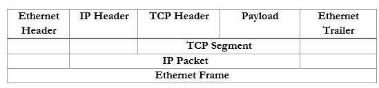
If we take the Payload from an IP packet, we can further dig inside it to find that it has its own header. This Payload is known as a Segment. If we were using TCP or UDP as our protocol for sending data, our Segment might look like this:

You don’t need to worry too much about these now but
- Source Port. The port that the data originated from.
- Destination Port. The protocol that the data is travelling to.
- Flag. A flag tells us whether the segment was sent to establish a connection or to acknowledge receipt of some other data.
- Payload. The actual data we are sending.
In summary, an ethernet frame looks like this
We can further summarize the contents and group them by OSI Layer.
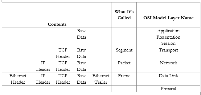
Now that we understand the model, we will revisit each topic in more depth.