
1.2 Explain the characteristics of network topologies and network types
- Mesh
- Star / Hub-and-Spoke
- Bus
- Ring
- Hybrid
- Network types and characteristics
- Peer-to-Peer
- Client-Server
- Local Area Network (LAN)
- Metropolitan Area Network (MAN)
- Wide Area Network (WAN)
- Wireless Local Area Network (WLAN)
- Personal Area Network (PAN)
- Campus Area Network (CAN)
- Storage Area Network (SAN)
- Software-Defined Wide Area Network (SD-WAN)
- Multiprotocol Label Switching (MPLS)
- Multipoint Generic Routing Encapsulation (mGRE)
- Service-Related Entry Point
- Demarcation Point
- Smartjack
- Virtual Network Concepts
- vSwitch
- Virtual Network Interface Card (vNIC)
- Network Function Virtualization (NFV)
- Hypervisor
- Provider links
- Satellite
- Digital Subscriber Line (DSL)
- Cable
- Leased Line
- Metro-Optical
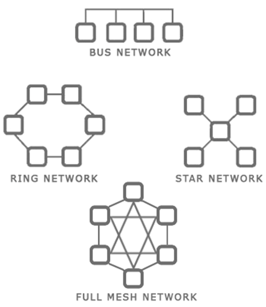
There are several types of network topologies
- Star – the star shaped network consists of a central hub and branches that connect to it. Most local ethernet networks are star-shaped. A central switch connects to multiple client devices such as computers and printers. A star network is also known as a hub-and-spoke.
- Ring – a ring network is one where each device connects to two neighbors, and no device is central. A ring network provides redundancy because the devices can continue to communicate even when one link fails. The ring network is common with large routers on the internet, which may have multiple routes.
- Bus – a bus network is where multiple devices share the same physical cable. Ethernet does not function with a bus network, but some forms of industrial communication do.
- Mesh – a mesh network is where each device has direct links to several other devices. A mesh network provides the most redundancy because the devices can continue to communicate even when multiple links have failed.
A mesh network is not possible with client devices such as computers and printers, because each typically has only one network interface. The mesh network exists for the backbone of the internet. - Hybrid – a hybrid network is a combination of the above types.
When you plan out your network, you should think about
- The size of your facility or campus
- The types of devices that you plan to connect
- The bandwidth that is required in each portion of your facility or campus
- The bandwidth that is required between portions of the facility or campus
- Whether fiber or copper connections are required
- The cost to acquire and maintain each network device
- The future needs of the organization and the expected growth
- The level of redundancy required
Some ideas
- The backbone of the internet is a mesh network in that every major ISP network is connected to several other ISP networks. This offers redundancy by providing multiple pathways for data transmission.
- A small office or home might have a star network where all the devices connect to a central modem/router.
- A larger office might have a star or hybrid star network with multiple layers. For example, a core switch in the main server room will feed smaller switches on each floor. Each client device will connect to one of these smaller switches.
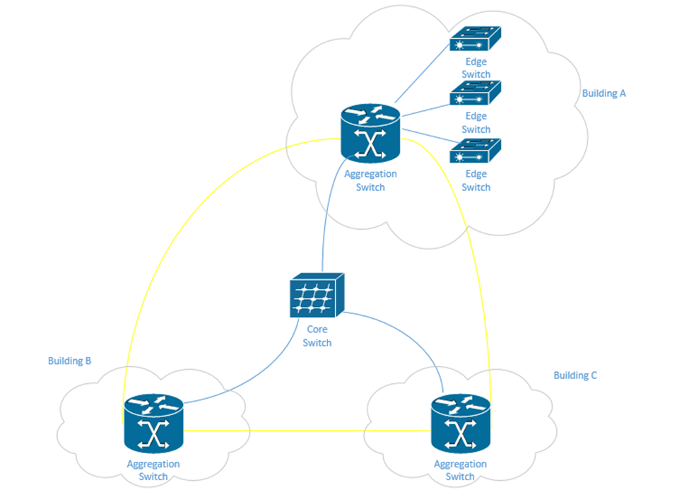
- A corporate or university campus with multiple buildings will have a star or hybrid star network. A core switch will be in the main server room and will feed a smaller aggregation switch at each building. Depending on the size of the building, it may have multiple edge switches, or devices may connect directly to the aggregation switch.
The campus may also have a fiber optic ring network that surrounds the entire campus. A ring provides additional redundancy. One benefit of the ring is that it can be constructed in the early stages of the campus. As more buildings are added, the ring can be cut and new buildings can be spliced onto it without having to install additional fibre.
In the following example, in yellow, we have a fiber optic backbone connected as a ring to the existing buildings – A, B, and C. We can add additional buildings onto the same backbone.
Each building has an aggregation switch that connects to the core switch. Building A has edge switches that connect to the aggregation switches. User devices in Building A can connect directly to each edge switch. User devices in Building B and C can connect directly to the aggregation switches.
We could draw the core switch as being on the backbone instead of being directly connected to each aggregation switch. If the fiber has enough capacity, we can directly connect the core switch to each aggregation switch without any issues.
Let’s look at some network types.
- Peer-to-Peer. You might recognize this from file sharing applications. Peer to Peer is a distributed architecture where every computer acts as a server to the other computers. A peer makes some of its resources available to the other peers without the use of an intermediate server.
Peer-to-Peer networks are used by file sharing applications, cryptocurrencies, Microsoft Windows update, and some other applications. In general, the devices on the P2P network do not have direct physical connections to one another and instead operate on top of another network. For example, you can set up a P2P network using devices on your office LAN. - Client-Server. A Client-Server network is one where multiple devices request content or communicate with a central server.
Examples of Client-Server networks include corporate file sharing, websites, and e-mail systems. For example, when you visit a website, that website is hosted on a server and your computer is the client. Multiple clients can connect to the same web server.
The Client-Server network also operates on top of another network such as a LAN or WAN. - Local Area Network (LAN). A LAN is the network in your office or home. It consists of devices connected behind a router (a router separates the LAN from the WAN).
- Wide Area Network (WAN). A WAN connects multiple networks together across long distances. It allows devices in multiple locations to act like they’re on the same network. An organization with offices spreads all over the country might connect them through a WAN. An internet service provider (or multiple ISPs) will own the backbone infrastructure that makes the WAN possible. Essentially, the company is paying the ISP a large amount of money to prioritize the traffic between its offices. If the ISP doesn’t own the entire backbone, then it negotiates with other ISPs to also prioritize the traffic in exchange for a portion of the fees.
WAN may also refer to standard internet connections such as DSL, Cable, Fiber, Broadband, etc. (i.e. connections that introduce your network to the outside world). - Wireless Wide Area Network (WWAN). A WWAN is a WAN but delivered over a cellular modem. WWANs are increasingly popular as back up connections and also for remote sites where the cost of extending a fiber optic cable would be prohibitive.
- Software-Defined Wide Area Network (SD-WAN). An SD-WAN is new technology that allows a company to connect multiple offices without the expense of a traditional WAN. It does so by connecting standard internet connections to an SD-WAN router at each office.
The SD-WAN router uses the internet connections to connect to cloud service providers and route traffic just as a traditional WAN would do. Since cloud service providers have data centers throughout most of the world now, and own the backbone infrastructure between those centers, the only slow portion of the SD-WAN will be between the office and the cloud. The result is the performance that is similar to a standard WAN without the cost. - Metropolitan Area Network (MAN). A MAN is larger than a LAN and can link multiple LANs together in a geographic area like a city. An organization with multiple offices in the same city might use a MAN.
- Wireless Local Area Network (WLAN). A WLAN is a portion of the LAN that is wireless. When wireless access points are connected to the LAN, they connect wireless clients with the rest of the LAN.
- Personal Area Network (PAN). A PAN is a small network formed by a user and his devices (such as a cell phone, tablet, and laptop). PANs are typically wireless and may use technologies like Bluetooth.
- Campus Area Network (CAN). A CAN is a network at a campus like a university or hospital. It may connect multiple LANs together. A CAN might be considered a LAN if no routers are involved. A CAN is different from a WAN in that the campus owns the infrastructure between the LANs.
- Storage Area Network (SAN). A SAN is a network that connects storage appliances to servers. A storage appliance is a type of hardware that is dedicated to storing large amounts of data. SANs could use ethernet or Fiber Channel.
- Multiprotocol Label Switching (MPLS). MPLS is an ISP technology that allows data packets to be routed from point to point across any type of transport medium (copper, fiber, or antenna), and via any protocol.
An ethernet packet is transported from the customer site to the ISP over the MPLS. The ISP uses ethernet (its own internal LAN) to transport the packet to its destination. From there, it exits and uses the MPLS to get to the destination customer site. - Multipoint Generic Routing Encapsulation (mGRE). mGRE was developed by Cisco. It allows a company with multiple sites to establish a VPN connection between them. A VPN allows a company to establish a “tunnel” between two or more sites. The traffic between the two sites is packaged and encapsulated over the tunnel. A VPN allows the sites to act like they are on the same network.
A VPN has poor performance compared to a WAN, but is less expensive, and can be established over standard internet connections.
Normally, a VPN must be manually configured on the router at each customer site. When the customer sites have public IP addresses that change, the routers must be manually reconfigured each time that the IP address changes.
When there are many VPN sites, the VPN is created as a “hub and spoke”, so that there is a central VPN server that connects to many branch offices. This way, each branch is not attempting to establish dozens of connections with other offices (which would overload the routers). But a large number of VPN connections can overload the VPN server as well.
mGRE allows the VPN tunnels to be created dynamically as required using Next Hop Resolution Protocol (NHRP). When the addresses of the spoke sites change, mGRE can use NHRP to find the new ones. Effectively, when a spoke site realizes that its IP address has changed, it calls up the hub and lets it know.
How does internet get into your building?
In legal terms, the Demarcation Point is where the ISPs equipment stops, and the customer’s equipment starts. It may also be known as the demarc, DMARC, MPOE, main point of entry, MPOP, or minimum point of presence. It might also be called the Service-Related Entry Point.
The customer may own some or all the customer premises equipment (CPE) or the ISP may own some or all of it.
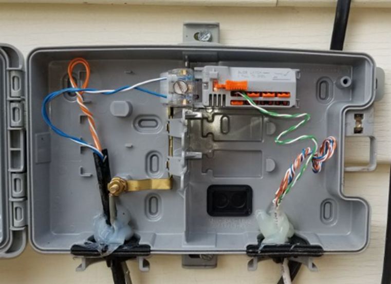
A demarcation point may be a termination block (such as a 66-block or 110-block), where wiring from the ISP is terminated. Or it may consist of a NID (Network Interface Device) such as the one below. Note that this NID has two sides – an ISP side and a customer side. The NID is usually installed outside a house or building. In a large office building or shopping mall, the demarcation point may be a large room with thousands of pairs of wiring.
What if the customer’s equipment is too far from the demarcation point? The ISP must then supply a demarcation extension. This is also known as a Service Interface Extension or inside wiring. The customer must typically pay for the cost of the extension.
An ISP may install a CSU/DSU (channel service unit/data service unit) at the demarcation point. The CSU/DSU converts the customer’s digital signal into an analog signal that travels over the telephone network.
Another device is called a Smart Jack. Where did the Smart Jack come from? In the past, to reduce competition, ISPs supplied and owned all the Customer Premises Equipment. ISPs used proprietary protocols to prevent customers from connecting their own CPE (such as modems). Eventually, the US federal government made it illegal and required each ISP to provide the customer with a physical wire connection, known as an RJ48. The problem was that the ISPs preferred to install their own equipment so that it could run diagnostic tests on the circuit. What if the customer complained that the internet wasn’t working? If the ISP owned the equipment, it could connect to it and perform diagnostic tests. If the customer owned the equipment, it couldn’t.
The solution was to create a Smart Jack. The smart jack is an electronic device with an RJ48 handoff that the customer could connect to. On the ISP side of the smart jack, they can monitor the connection and perform diagnostic tests. On the customer side, there is a standard RJ48 customer connection that satisfies the requirement of the federal government.
The ideas behind the network delivery (especially the LAN) have been expanded to virtualization technologies. Virtualization allows us to create multiple “virtual” servers on a single physical server. But when we try to connect those multiple servers to each other or to the physical network, we must employ network virtualization. This is related to Software Defined Networking (SDN). We will explore this topic in more details later.
But we have four ideas
- Hypervisor. The Hypervisor is a software application that runs as the base operating system on a physical server. It allows the user to create multiple virtual servers, which run inside the hypervisor. The hypervisor tricks the virtual servers into believing that each of them has separate physical hardware.
The advantage of a virtual machine is that we can maximize the resources of our hardware. We can run multiple servers on the same physical hardware instead of having separate servers for each application.
We can also run the same virtual server across multiple physical servers. This provides redundancy in case one of the physical servers were to experience a hardware failure. It also allows us to increase the resources of a high-demand virtual server so that it can have the computing power of multiple physical servers. - vSwitch. The vSwitch is a virtual switch that runs inside the Hypervisor and connects the multiple virtual servers. There can be multiple vSwitches if required.
- Virtual Network Interface Card (vNIC). Each virtual server can have one or more vNICs that allow the server to connect to the switch.
- Network Function Virtualization (NFV). NFV takes this a step further and virtualizes load balancers, routers, and firewalls, which used to require dedicated hardware.
Consider in a network that each function must be performed by a proprietary device, such as a load balancer, a firewall, a router, etc. For example, you may have a Cisco router or Cisco firewall. Now, what if we want to increase the capacity of the physical router? We would have to buy a larger router. What if we want to install a physical router in a cloud infrastructure, or inside a virtual machine? It is not possible.
With NFV, we can take the software component of the proprietary router, firewall, or load balancer and install it on a server (inside a hypervisor) virtual machine. The manufacturer of the proprietary hardware will create an “image” of the operating system on their router/firewall/load balancer, which we would then install as a separate virtual machine and virtually connect it to the other components. The virtualized infrastructure would run on generic physical hardware, which can be scaled up or down as required. It also requires less space in some cases.
Remember that the physical hardware must still physically connect to the internet, so there will always be a need for some physical infrastructure.
When I buy an internet connection, how is it delivered?
ISDN or Integrated Services Digital Network was an older type of internet connection. It delivered data, voice, video, or fax over the same physical telephone line. ISDN supported connection speeds of up to 128 kbit/s. At least two simultaneous connections were possible over a single ISDN line. ISDN was a circuit-switched network (between the user and the ISP) that provided subscribers with access to a packet-switched network.
ISDN technology was later used to develop the PRI, or Primary Rate Interface. PRI is a technology that can transmit multiple analog phone lines over a single pair of wires. Previously, each phone line required a separate pair of wires. The PRI delivers 23 “channels” of voice traffic and one overhead channel. That is, a PRI can handle up to 23 simultaneous phone calls on a single pair of wires. A phone call coming in over a PRI is tagged with the number that was dialed. This way, an organization could have hundreds of phone numbers on a single PRI, if they do not have more than 23 simultaneous phone calls.
A PRI is delivered over a T1 line, or Transmission System 1 line. The total bandwidth carried by a T1 is 1.544 Mbit/s. Each channel is 64 kbit/s. The different channels are separated with a time-division multiplexing algorithm. In other words, each channel receives a separate time slot for when its data is transmitted.
Who decided that T1 should be 1.544 Mbit/s as opposed to some other number? AT&T did. They invented T1 in the 1960s because they were trying to send telephone traffic long distances without the use of expensive equipment.
I need to go off on a tangent. Think of water flowing from a garden hose. It is continuous. It never stops. I could measure the flow rate every 10 seconds, or every second, or every 1/10th of a second, or every 1/100th of a second, etc.. This is known as my “sample rate”. What if the flow rate is 1 gallon/second at my first measurement and 1.1 gallons/second at my second measurement? Did it instantly jump from 1 gallon/s to 1.1 gallons/s? No. Between measurements it might have been 1.01, 1.02, 1.03 g/s, etc.. The point is, we can’t take an infinite amount of measurements. It’s physically impossible.
When you’re talking on the phone, the phone isn’t listening to you all the time. It’s taking samples of your voice and sending them to the network. If the samples are taken at short enough time intervals, the call can be reconstructed on the other side without any noticeable loss of quality. Our brains fill in the blanks.
A phone measures your voice 8000 times per second (8000 Hz). Each measurement is 8 bits in size. If I have 24 channels, then I need 8 bits x 24 channels = 192 bits/measurement. I must add one extra bit called the “framing” bit, which is used in error handling. So, I have 193 bits per measurement. Since there are 8000 measurements per second, 193 x 8000 = 1544000 bits/s or 1.544 Mbit/s.
Why did they choose 24 channels and not some other number? Rumor has it that AT&T performed some tests on cables they had installed underground in Chicago. They increased the transmission rate until the quality was just barely unacceptable. They had to stop at 24 channels.
Eventually other phone companies figured out a way to increase the bandwidth on a wire, and other T’s were developed. Another common T system is T3, which carries 44.736 Mbit/s.
Another system competing with the T1 is the E1, which carries up to 32 channels, for a total of 2.048 Mbit/s. Only 30 channels are useful, because E1 uses one channel for synchronization, and one for management. The E1 system uses time-division multiplexing just like the T1 system.
Other phone companies found ways to increase the bandwidth of the E1 system, resulting in the E2 (8 Mbit/s), E3 (34 Mbit/s), and E4 (140 Mbit/s) systems.
What if we need to transmit data long distances, and the copper wiring just won’t cut it? That’s where fiber comes in. Across large ISPs, Optical Carrier transmission rates have become standardized. The standard transmission rate is OC-1, which carries 51.84 Mbit/s. We can measure the transmission rate of a line in multiples of the standard rate. We can give this line a name in the format of OC-#, where # is the multiple. For example, if a line has a transmission rate of 103.88 Mbit/s, that is double the standard rate. We would call this line an OC-2 line.
Three common OC lines are the OC-3, which has a rate of 155.52 Mbit/s, OC-48, which has a rate of 2488.32 Mbit/s, and the OC-192 line, which has a rate of 9953.28 Mbit/s. The OC-48 line is used by many ISPs. OC-192 can work with 10 Gigabit Ethernet. Some undersea fiber optic cables use transmission rates of OC-768 (approximately 39 Gbit/s).
OC uses a system called SONNET, or synchronous optical networking protocol. Remember that data is broken up into packets, and that each packet has a header. The difference between a SONNET transmission and other types of transmissions is that the packet and header are sent at the same time. The header is mixed up with the rest of the packet.
In a smaller organization, the type of internet connection delivered may be DSL, Metropolitan Ethernet, Cable Broadband, or even Dial-Up.
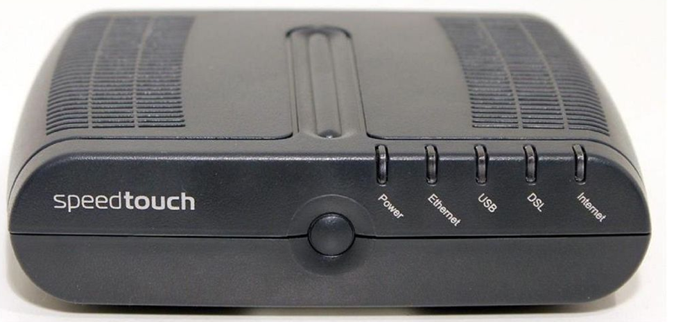
DSL or Digital Subscriber Line is delivered over a phone line. It may provide speeds of up to 150 Mbit/s. A subscriber will require a DSL modem to convert the signal from a phone line to an ethernet cable. The same phone line can be used to transmit voice simultaneously. Internet traffic is transmitted at a different frequency from voice traffic. At the ISP’s network, these are filtered and sent to different types of equipment. Voice traffic is routed to a telephone switch, while data traffic travels to an internet router. The device that performs this filtering is called a digital subscriber line access multiplexer or DSLAM. Each DSL modem must synchronize with the DLSAM so that they can filter out noise and errors. A DSL modem will typically have a “link” or “DSL” light that shows its synchronization status. Below is a photo of a common DSL modem.
Cable Broadband is a product competing with the DSL. While DSL is typically provided by a phone company Cable Broadband is provided by a cable television provider and is delivered over a coaxial cable. A subscriber requires a cable modem to connect to the network. At the provider’s facility, a device known as a cable modem termination system is installed. This device synchronizes with the subscriber cable modems and transfers their data to the internet.
It’s called broadband because multiple signals travel over a single wire at the same time, each occupying a different frequency. This is compared with other types of connections, which are known as baseband. On a baseband connection, a single signal travels over the wire.
The slowest form of internet is Dial-Up, but Dial-Up is generally available anywhere a phone line is. A Dial-Up modem converts an analog phone signal to and from a digital internet signal. The modem first calls a number dedicated by the ISP. The modem and ISP’s equipment synchronize and then transmit/receives data. An ISP does not require additional special equipment to maintain a Dial-Up service. A Dial-Up connection works at speeds of up 56 Kbit/s.
Many of these technologies are being replaced by Metropolitan Ethernet, also known as metro Ethernet, Ethernet MAN, or metropolitan-area Ethernet. How does it work? An ISP builds a large ethernet network in a city (or in a downtown area) and allows subscribers to connect to it. Why use metro Ethernet? It’s cheaper to maintain an ethernet network because it does not require special equipment at the subscriber’s side (modems) or at the ISP’s side (multiplexers and termination systems). The ISP already owns all of the backbone cables in the city.
The ISP may connect to the customer site via a router or switch. Traffic from different customer sites is aggregated with larger switches. Multiple MANs can be aggregated via an IP-MPLS system.
An ISP may provide MPLS over its metro ethernet. An ethernet packet is transported over MPLS from the customer to the ISP. The ISP uses ethernet to transport the packet to its destination. Why use MPLS? The ISP can handle traffic from any type of medium or protocol. It is easy to perform end-to-end troubleshooting of an MPLS network than a pure ethernet network.
A new alternative to metro Ethernet is metro optical (although nobody calls it this). It is basically metro Ethernet delivered over a fiber optic cable.
A leased line is a dedicated circuit between two offices. It is permanently connected. It may also be called an Ethernet leased line. A company that wants to connect two offices with the same LAN can rent a leased line from an ISP (subject to availability). The leased line may have an unlimited bandwidth or be limited to a specific speed.
In rural areas, internet may be delivered over a satellite modem. Satellite has a high latency and is expensive, but in some areas, it is the only choice.
An internet connection can be transported via Copper, Fiber, Satellite, or Point-to-Point antenna.
Copper is the oldest transmission medium. Traditionally, the phone and cable companies owned copper cable for transmitting phone calls and cable television. They later began using them for transmitting internet. DSL, Dial-Up, cable, T1, E1, T3, and E3 are transmitted over copper.
Fiber is quickly replacing copper, even in residential neighborhoods. Most fiber is being installed by the phone companies, which own the right to install additional wiring. Cable companies and cellular providers own some fiber as well. Metro Ethernet is typically delivered over fiber, although it could be delivered over copper.
A satellite internet connection is suitable for rural areas that have no physical wiring. The biggest problem with satellite internet is that it has high latency. It takes a long time for a signal to travel from a subscriber’s satellite dish to a satellite in the earth’s orbit (up to 120 ms). The total latency can be up to 1000 ms, whereas the latency of a broadband connection may be only 40 ms. A subscriber must have a “line of sight” between their satellite antenna and the satellite in the sky. If it is blocked by trees or clouds, the signal will suffer.
A traditional satellite dish can only receive data. Since the internet is two ways, a satellite internet connection requires a transmitter that points back at the satellite in the sky. Sometimes, the satellite connection is combined with a dial-up connection. Data that requires low latency is transmitted over the dial up connection.
Satellite internet can also be transmitted over a portable modem. These transmit with a speed of about 500 kbit/s but cost up to $5 per megabyte of data transmitted.
A Point-to-Point antenna is another less common way to provide internet service without wiring. A service provider installs a transmitter at the top of a large tower in the center of a city. Each subscriber installs an antenna on their rooftop, pointed towards the tower. The internet is transmitted over a radio signal. The subscriber connects his antenna to network equipment (typically provided by the ISP), which then connects to his network.
How can you decide which internet connection you need? We will discuss this in more detail, but in general
- What bandwidth do you require? Think about the performance of the internet connection.
- How many offices do you have and where are they located? This will affect the types of internet connections available.
- Do you need to connect the offices together over a WAN or SD-WAN, or will a VPN be suitable?
- What is the budget and what is the cost of the different options?
- Do you need redundant connections? Consider some common scenarios
- A single office might have one broadband connection and one back up cellular connection.
- A business with multiple offices across many states/provinces will have a WAN (although many businesses are switching to SD-WAN). Rural offices connect back to the main offices over a VPN since the cost of a WAN in those areas may be too expensive.
- An office may route normal internet traffic over a broadband connection and inter-office traffic over a WAN. This allows them to purchase a lower-capacity WAN.
- Some remote offices may connect via satellite or cellular.
- A single office might have one broadband connection and one back up cellular connection.