
1.3 Summarize the types of cables and connectors and explain which is the appropriate type for a solution
- Copper
- Twisted Pair
- Cat 5
- Cat 5e
- Cat 6
- Cat 6A
- Cat 7
- Cat 8
- Coaxial/RG-6
- Twinaxial
- Termination Standards
- TIA/EIA-568A
- TIA/EIA-568B
- Twisted Pair
- Fiber
- Single-Mode
- Multimode
- Connector Types
- Copper
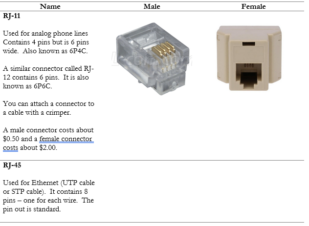
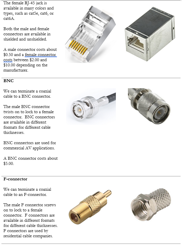
- RJ-45
- RJ-11
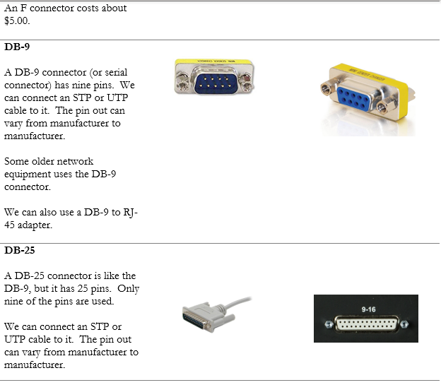
- BNC
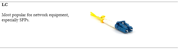
- DB-9
- DB-25
- F-Type
- Fiber
- Local Connector (LC)
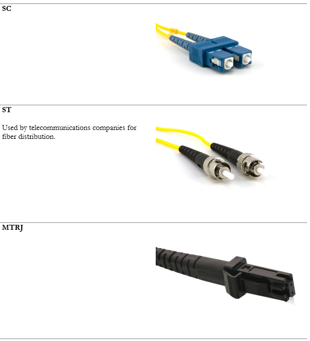
- Straight Tip (ST)
- Subscriber Connector (SC)
- Mechanical Transfer Registered Jack (MTRJ)
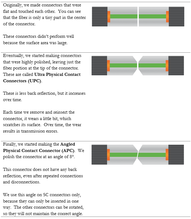
- Angled Physical Connector (APC)
- Ultra Physical Connector (UPS)
- Transceivers/Media Convertors
- Transreceiver Type
- Small Form-Factor Pluggable (SFP)
- Enhanced Form-Factor Pluggable (SFP+)
- Quad Small Form-Factor Pluggable (QSFP)
- Enhanced Quad Small Form-Factor Pluggable (QSFP+)
- Copper
- Cable Management
- Patch Panel/Patch Bay
- Fiber Distribution Panel
- Punchdown Block
- 66 Block
- 110 Block
- Krone
- BIX
- Ethernet Deployment Standards
- Copper
- 10Base-T
- 100Base-TX
- 1000Base-T
- 10GBASE-T
- 40GBASE-T
- Fiber
- 100BASE-FX
- 100BASE-SX
- 1000BASE-SX
- 1000BASE-LX
- 10GBASE-SR
- 10GBASE-LR
- Coarse Wavelength Division Multiplexing (CWDM)
- Dense Wavelength Division Multiplexing (DWDM)
- Bidirectional Wavelength Division Multiplexing (WDM)
- Copper
Now we have an idea of how our network will work, we can look at the types of cables we can use to connect it. There are two main choices: copper or fiber.
There are two types of network cable: Copper and Fiber. When do we use copper and when do we use fiber?
Most of the copper wiring in use is Unshielded Twisted Pair (UTP). This is a standard ethernet cable that contains eight wires, twisted into four pairs. The twists are designed to cancel out most forms of electromagnetic interference (from radio waves and nearby power lines). UTP can be run up to 100 meters.
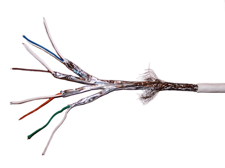
For more advanced applications, we can use a Shielded Twisted Pair (STP) cable. This is also known as F/UTP cable. The difference is that the STP cable contains a foil around the wires. The foil blocks out even more electromagnetic interference than the twists. The foil connects to the termination point on each end of the cable and acts as an electrical ground. STP cable is used in applications such as video transmission and in areas where there is a large amount of interference. If we peel back a cable, we can see the difference.
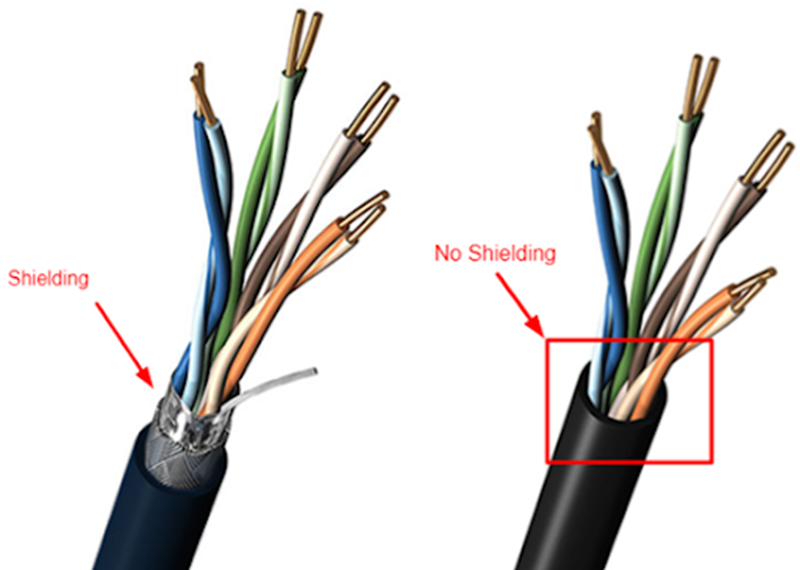
If we went crazy, we could buy a cable that had a separate shield around every pair. The shield protects the wires from electromagnetic interference. It also protects individual wire pairs from cross-talk (interference from a neighboring wire pair).
Most device network interfaces accept a copper (UTP or STP) connection. That includes switches, IP cameras, computers, and VoIP phones.
Another form of copper wiring is coaxial. Coaxial wiring can be run up to 500 meters. It consists of a central conductor with a braid wrapped around it. The braid shields the central conductor from electromagnetic interference that could disrupt the signal.
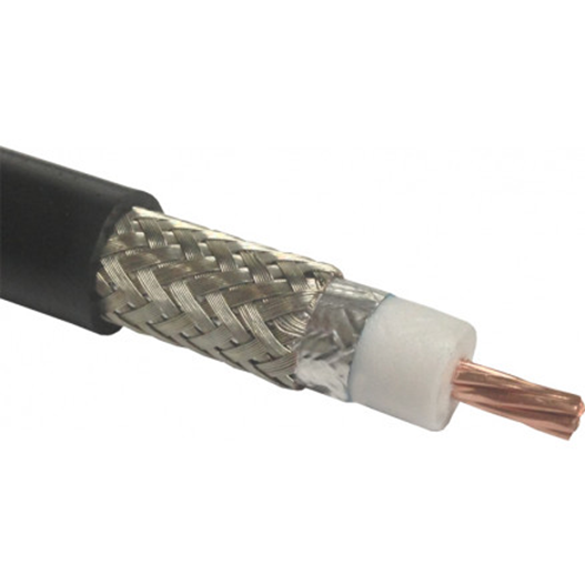
Coaxial cable can be run up to 500 meters. It is used to connect older analog cameras, satellite systems, antennas, and cable modems.
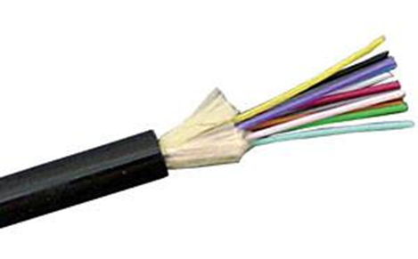
Fiber optic cable can be run longer distances than copper. It also has a larger bandwidth. But fiber is more difficult to install than copper. It requires specialized equipment to test and terminate. A fiber optic cable uses light to transmit data.
We can’t connect a fiber optic cable to standard host devices. For example, a VoIP phone or computer will not have a fiber optic connector. If we ran a fiber optic cable to a far away computer, we would need a device called a media converter to convert the fiber to copper.
Fiber comes in two forms: single-mode, and multimode. Single mode cable can be run upwards of 200 km. The light signal travels down the center of the cable as a single signal. Multimode cable can be run up to 1 km. The light bounces up and down inside the cable.
A single copper cable contains eight wires. When connected, the copper cable carries data in multiple directions. But a single fiber optic cable can contain multiple strands. A single strand carries data in only one direction. When we peel back the fiber optic cable, we find multiple strands, which can be color coded. We need at least two strands to make a circuit and carry data. Most common sized fibers have six or twelve strands.
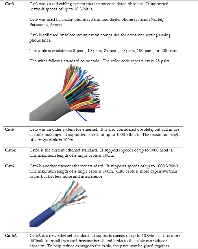
Some of the most common copper standards are outlined in the table below.
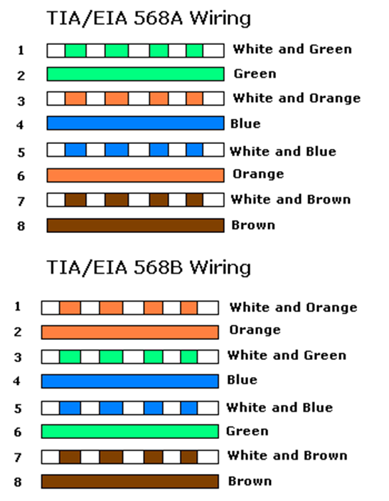
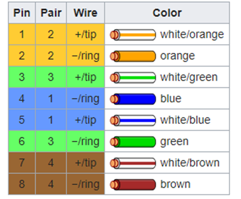
There are two methods for terminating a cat5e/cat6/cat6A cable. The methods are known as 568A and 568B. Remember that the ethernet cables contain 4 pairs of wires (colored as blue, orange, green, brown). The difference between 568A and 568B is that the position of the orange and green wires is swapped.
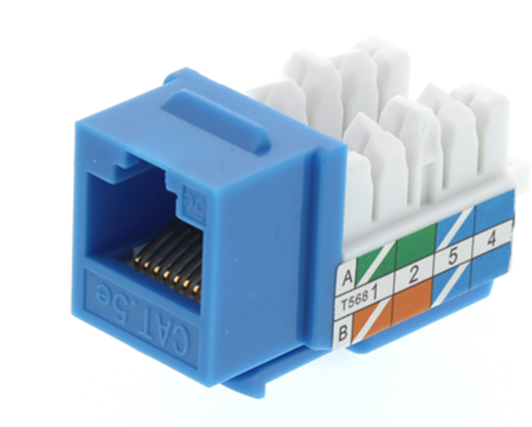
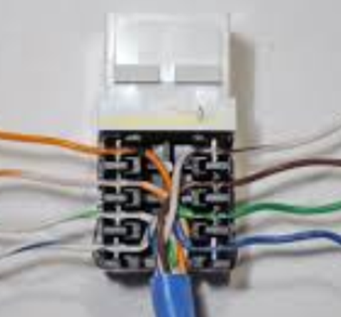
If we look at the side of a cat5e jack, we can see that the manufacturer has marked a color code for “A” style terminations and “B” style terminations. On the other side of the jack, we would see similar markings. The color order may vary from manufacturer to manufacturer.
We should insert the wire into the correct colored slot on the jack or patch panel and then terminate it with a punch-down tool of the appropriate size.
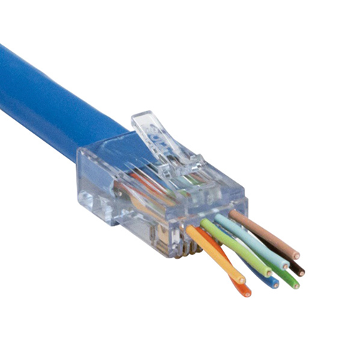
We could also terminate the cable to a male connector. The male connectors follow the same color code as the female connectors. We use a tool called a crimper to secure the wires inside the connector.
Both 568A and 568B are acceptable termination methods. A cable should be terminated with the same method on both sides. An organization may require the cable to be terminated using a specific method. Most organizations prefer 568B, and most governments prefer 568A.
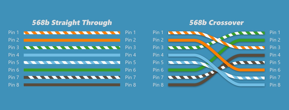
If we terminate the cable in the same order on both ends, we call it a straight through cable. If we terminate the cable as 568A on one end and 568B on the other end, the orange and green pairs become crossed. This is called a crossover cable.
Why would we make a cross-over cable? Network devices usually use the orange and green pairs to communicate. A device like a switch transmits over the orange pair and listens on the green pair. A device like a computer transmits on the green pair and listens on the orange pair. If we connect a computer to a switch, collisions do not take place.
If we want to connect two computers together or two switches together, they will try to talk on the same pair and listen on the same pair. No data will get through. The device doesn’t know the color of the wire; it only knows the position of the wire. If you punched the blue wire in the orange wire’s spot, the device would communicate over the blue wire.
So, if we use a cross-over cable, then one switch will transmit over the orange pair (wires 1 and 2) and listen over the green pair (wires 3 and 6). The other switch will transmit over the green pair (wires 3 and 6) and listen over the orange pair (wires 1 and 2).
We don’t need crossover cables to connect switches anymore. If two modern switches are connected via a straight through cable, they will immediately detect the collision and agree on who will use which wire pairs.
The coaxial cable is available in many sizes. The number relates to the thickness of the core conductor in the center. The two most common RG-59 and RG-6. Coaxial cable is used for satellite systems, surveillance cameras, cable modems, and other analog systems. Your ISP may install it, but I do not recommend it unless absolutely required.
| RG-59 | RG-59 is used for short lengths and is cheaper than RG-6. |
| RG-6 | RG-6 is used for satellite systems and surveillance cameras. It can provide a better-quality signal than RG-59 |
Twinaxial cable or Twinax is a coaxial cable with two internal conductors. Twinax can be used for 10GB or 40GB Ethernet. A 100GB version is being developed. The maximum length of a Twinax is 10 meters. Twinax is being used to connect servers, switches, and storage appliances in data centers, where a high bandwidth, low latency connection is required.
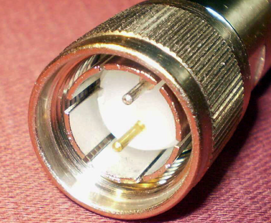
After we install the cable, we must terminate it somehow. We must put a connector on the end so that we can plug it into something. A copper connector can be male or female.
We also have connectors for fiber optic cables. We can purchase adapters for any type of fiber connector. Notice that fiber cables do not have female connectors, only male. We can convert a male connector to a female connector by connecting it to a coupler.
After a fiber connector is manufactured, it is polished. The angle at which it is polished affects its data transmission. Two fiber connectors must be mated together so that they can transmit data.
Look at this Cisco switch. On the left are 48 copper ports. Each one can accept a single RJ-45-terminated cable. On the right are four additional ports – the bottom two are copper and the top two are “SFP”, or small form-factor pluggable transceiver.
You can’t plug a cable into an SFP port.
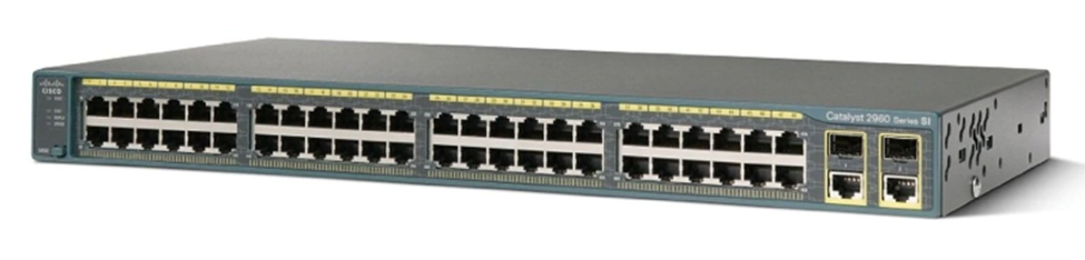
So, what’s the point? Well, there are many types of cables and available speeds – copper, single-mode fiber, multi-mode fiber, 10Gbit speeds, 1Gbit speeds, etc. The manufacturer of the switch can’t sell a different type of switch for every possible connector. It would result in too many switch combinations. Instead, the manufacturer adds some “SFP” ports.
Look at this switch. Almost all its ports are SFP ports.
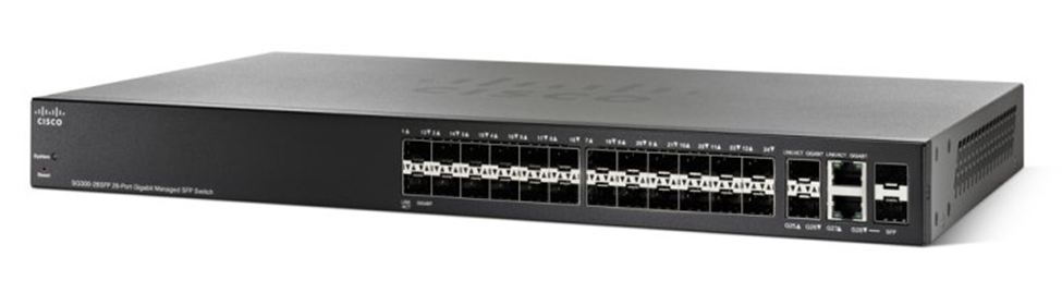
You figure out what kind of connections you require – copper or fiber (single-mode or multi-mode). And you decide the speed that you require – 1GB, 10GB, or 40GB. And if you’re using fiber, you decide what kind of connector you’re using LC, SC, etc.. Then you buy the right SFPs and insert them into the switch. An SFP could cost between $10 and $2000 depending on the speed and cable types. You can mix and match SFPs on a single switch.
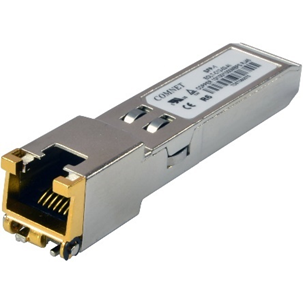
An example of a copper SFP is below. You insert the SFP into an SFP port and then you insert the cable into the SFP. SFPs are hot-swappable (that means we can change the SFP while the switch is running and the switch will recognize the new SFP).
The maximum speed of an SFP is 1 Gbit/s, but the maximum speed of an SFP+ is 10Gbit/s. It is also known as an enhanced small form-factor pluggable transceiver. An SFP+ works with fiber and copper connectors.
For even faster speeds, such as those required in the networks of major Internet Service Providers, the QSFP or Quad Small Form-factor Pluggable transceiver can be used. The QSFP can provide speeds of up to 4 Gbit/s.
For even faster speeds, now there is the QSFP+, which provides speeds of up to 40 Gbit/s. There is also the QSFP14, which provides speeds of up to 50 Gbit/s, the QSFP28, which provides speeds of up to 100 Gbit/s, and the QSFP56, which provides speeds of up to 200 Gbit/s.
Below is an example of a fiber SFP. You will notice that it has space for two fibers. That is because a single stand of fiber typically operates in one direction at a time, whereas an ethernet cable operates in both directions at the same time. Thus, we would need two fiber strands to complete a “circuit”.
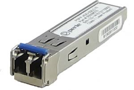
Some service providers use a bidirectional fiber, which allows the signal to travel in both directions at the same time. Each direction transmits a signal in a different wavelength. For example, we might transmit in 1310 nm and receive in 1550 nm. A bidirectional fiber allows a service provider to conserve their fiber resources when they are scarce.
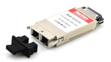
Before SFPs we had GBIC (Gigabit Ethernet and Fibre Channel) transceivers, but they were much larger. They only operated at rates of up to 1 Gbit/s.
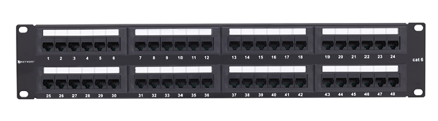
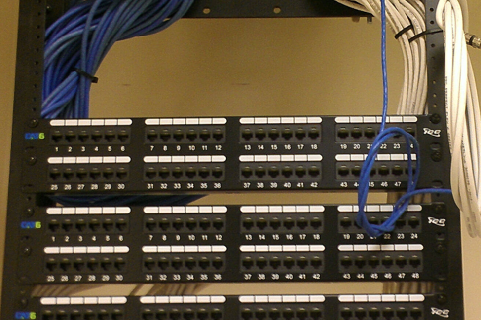
A common termination point for an ethernet cable is a patch panel. These panels are commonly available in 24-port and 48-port sizes. The panel fits into a standard network rack. Wall-mounted panels are also available.
At the back of the panel are spaces to insert each wire. We should peel the STP or UTP cable and stick each of the eight wires into the appropriate slot. We then use a tool called a punch-down tool to terminate the cable.
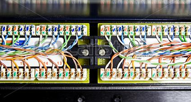
A panel costs between $50 and $600 depending on the manufacturer, number of ports, and whether it is cat5e, cat6, or cat6A. We can also use modular patch panels and insert jacks directly into them (which I recommend).
The slots in the back of the panel have a specific size. The most common size is “110”. Other sizes include 66, BIX, and Krone. Each size requires a punch-down tool with the correct shaped blade to insert the wire into the slot. The front of the panel looks the same, but the shape of the slots in the back will be different.
In a rack, the panels might look like the photo below
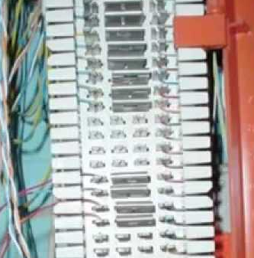
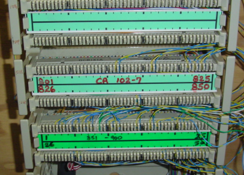
In a telecommunications system, we might use a wall-mounted block known as a 66, 110, or BIX block. Again, the name refers to the shape of the wire inserts.
The telecommunications blocks allow us to cross-connect a single wire at a time. We can connect many different types of copper wire to the block, including cat5e, cat6, or cat3.
Below is a 66 block. The blocks are used to cross connect cables. Wires coming from outside the system (wiring coming from a phone system or wiring coming from outside the building) are normally punched down to the left side of the panel. Building wiring is punched down to the right side. We add jumpers (the metal pieces in the middle of the block) to cross connect one side of the block to the other. Jumpers are also known as bridging clips.
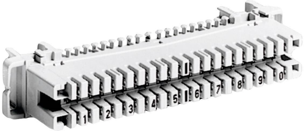
A 110 block is below. 110 blocks don’t use bridging clips but we can use a jumper wire to cross connect one side to another.
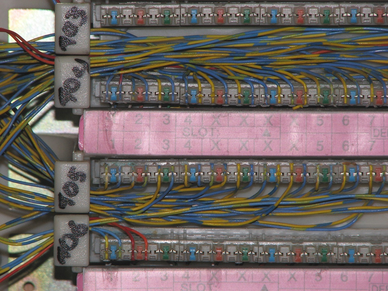
Similar to the 110 block is the BIX block. The BIX and the 110 blocks don’t take up much room.
Finally, we have the Krone block. Very few places use the Krone block.
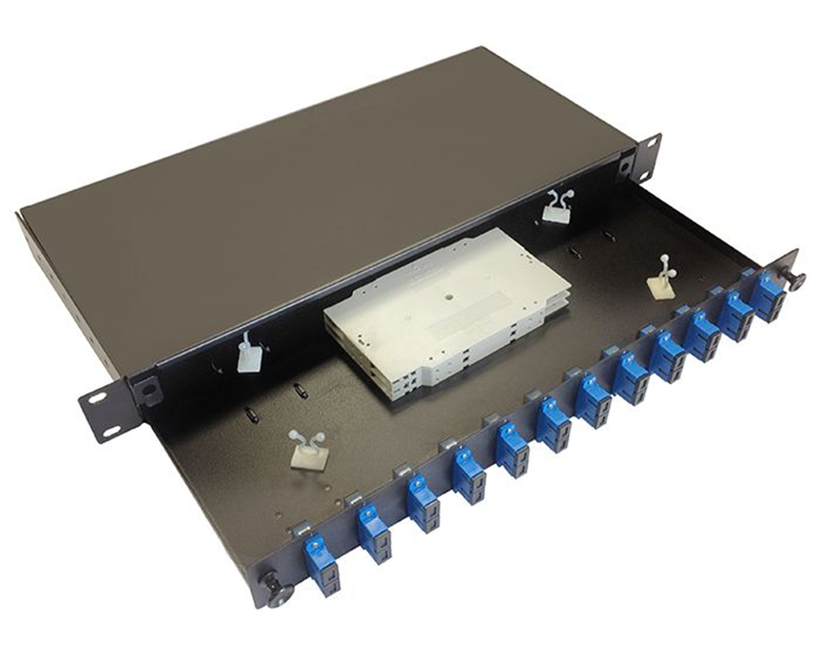
Fiber optic distribution panels can be rack-mounted or wall-mounted. Below is a rack-mounted patch panel. As you will notice, and as I said earlier, we can only terminate a fiber to a male end. The fiber panel below has female couplers at the front. We would run our fiber optic cable into the back of the panel and terminate it inside the panel. Then we can connect each terminated strand to the back of each coupler.
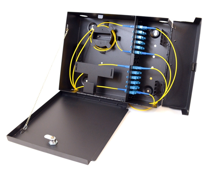
Below is an example of a wall-mount fiber optic patch panel. It also contains female couplers at the front. We can purchase the patch panels and the couplers separately, so that we can mix and match the types of connectors used by the system.
When two devices are connected via an ethernet cable, they will evaluate the wiring between themselves and agree on a speed and duplex setting, in a process known as autonegotiation. In a half-duplex setting, only one device can transmit at a time; the other device must listen. In a full-duplex setting, both devices can transmit and listen at the same time.
There are several standards for speed.
10Base-T was the original copper standard and could transmit at speeds of up to 10 Mbit/s. It could function over cat3 cable. 10Base-T is no longer popular.
100Base-TX came after. It can transmit at a speed of up to 100 Mbit/s over cat5 cable. 100Base-TX is also called 100BaseT or Fast Ethernet and uses two wire pairs – orange and green. One device listens on the orange pair and talks on the green pair, while the other device does the opposite. On a router, you might see ports labelled as FE for Fast Ethernet. The other four wires are not used.
1000BaseT is also known as Gigabit Ethernet. It uses all four pairs of an ethernet cable. 1000BaseT is the current standard, and you should not purchase network with components that operate at a lower speed than that.
A 100BaseT connection could be either full duplex or half duplex. A 1000BaseT connection must always be full duplex.
The next standard to develop was 10GBASE-T, which operates at 10 Gbit/s. 10GBASE-T requires cat6A cable but can operate over cat6 cable for short distances.
When 10GBASE-T came out, wireless access point manufacturers needed something better. As Wi-Fi popularity increased, manufacturers wanted to take advantage of the 10GBASE-T by implementing it in their access points. But building owners did not want to replace existing cat5e or cat6 wiring with cat6A. Thus, 2.5GBASE-T and 5GBASE-T were developed. They can provide 2.5 Gbit/s or 5 Gbit/s, respectively over existing cat6 cable.
Finally, 40GBASE-T was developed, which allows for speeds of 40 Gbit/s over cat8. 25GBASE-T with a speed of 25 Gbit/s and 50GBASE-T with a speed of 50 Gbit/s also exist. Both require cat8 cable.
An administrator can manually configure a switch/router/computer ethernet port to a specific speed and duplex setting but must then be careful to ensure that both connected devices/ports have the same settings, or they will not be able to communicate.
The standards that exist in the copper world also exist in the fiber world.
The early standard for fiber was 100Base-FX and 100Base-SX, which provided 100 Mbit/s over fiber. The FX standard worked over longer distances but used expensive lasers, while the LX standard worked over shorter distances and used cheaper LEDs.
1000Base-X is the standard for communication over fiber at 1Gbit/s. There are two main standards: 1000BaseLX uses single-mode fiber and can achieve distances of up to 10km, while 1000BaseSX uses multi-mode fiber and can achieve distances of up to 220 meters.
10GBaseT or 10 Gigabit Ethernet is a newer standard that allows devices to communicate at a speed of 10 Gbit/s. It can function over copper wiring or fiber. There are several fiber standards, including 10GBase-S (multi-mode fiber) and 10GBase-L (single-mode fiber).
10GBase-SR (for short range) provides speeds of 10 Gbit/s over multi-mode fiber at distances of up to 26m, while 10GBase-LR (for long range) provides speeds of 10Gbit/s over single-mode fiber at distances of up to 10km.
A 1000BaseLX SFP costs around $10 while a 10GBase-L SFP may cost up to $2000. Therefore, organizations prefer to use 1000Base-X when they can. 10 Gbit/s ethernet ports are only found on high-end infrastructure.
What if we have many signals to transmit simultaneously over a single fiber strand (or limited fiber strands)? We can combine the signal with a device called a multiplexer.
On one end of the fiber strand, we install a multiplexer, which joins optical signals (each with a different wave length) and sends them down the strand. On the other end of the strand, we install a demultiplexer, which separates the signals. There are three technologies here
- Coarse Wavelength Division Multiplexing (CWDM). Coarse refers to a wide separation between the wavelength of each signal. Specifically, the wavelengths are separated by 20 nm. For example, a signal at 1310nm and a signal at 1330nm can be transmitted over the same fiber at the same time.
- Dense Wavelength Division Multiplexing (DWDM). DWDM systems transmit signals with a much narrower wavelength separation. DWDM systems must operate very precisely as a small variation in the wavelength or the temperature of the laser can cause substantial loss in the signal. DWDM systems are used in very high bandwidth applications, and require repeaters every 100 km.
- Bidirectional Wavelength Division Multiplexing (WDM). Bidirectional WDM allows us to send a signal on a single fiber optic strand in both directions at the same time. This can happen because the signal in one direction has a different wavelength than the signal in the opposite direction.
How can you choose the best type of cable for your project?
- I don’t recommend coaxial for anything. The most common application is surveillance cameras, but I strongly recommend that you use ethernet based cameras.
- Install Ethernet cable between your server room and your wall outlets/surveillance cameras/wireless access points. The number of cables to each outlet depends on your needs, but for further guidance look at the BICSI TDMM (Telecommunications Distribution Methods Manual). The full design requirements are beyond the scope of this book.
- In general, use cat6 cable within your building and cat6A to the wireless access points. Remember that a single wall outlet is supporting only one device, but a wireless access point may support up to 50 devices, and thus a cable supporting a higher ethernet speed is warranted. Consider using cat6A for all your cabling if your budget allows.
- When the distance exceeds 100m, install multi-mode fiber. When the distance exceeds 1km, install single-mode fiber. Install a fiber optic cable with at least six strands so that there is adequate capacity for future upgrades. LC connectors are the most common.
- If you have an analog phone system, you may install some cabling between your telecommunications demarcation point and your server room. You can terminate this cabling to a BIX or 110 Block.
- Within a server room you may consider installing cat8 if required by your equipment. It may be better to purchase premanufactured cat8 patch cables and use them as required.
- 1 Gbit/s is the current minimum standard and you should configure your equipment to operate at this speed. Consider your needs and budget. Consider future upgrades, and whether it is better to buy faster equipment now or whether you will have funding to do it later. Connectors that operate at speeds faster than 1Gbit/s are more expensive.
- You may purchase switches that have the capability to operate at up to 40Gbit/s and then purchase the required SFPs at a later date (when the additional bandwidth is required).