
1.7 Explain basic corporate and datacenter network architecture
- Three-Tiered
- Core
- Distribution/Aggregation Layer
- Access/Edge
- Software-Defined Network
- Application Layer
- Control Layer
- Infrastructure Layer
- Management Plane
- Spine and Leaf
- Software-Defined Network
- Top-of-Rack Switching
- Backbone
- Traffic Flows
- North-South
- East-West
- Branch Office vs On-Premises Datacenter vs Colocation
- Storage Area Networks
- Connection Types
- Fiber Channel over Ethernet (FCoE)
- Fiber Channel
- Internet Small Computer Systems Interface (iSCSI)
- Connection Types
We are going to look at some more physical network designs. Remember earlier that we had a campus network with three layers? This is a common design in larger networks and consists of three layers.
- Core – the core layer is the backbone of the network. It consists of more advanced switches, which may connect to a router. Core switches connect to the aggregation switches.
- Aggregation – also known as the Distribution layer. This consists of switches that connect the core with the edge.
- Edge – the edge switches are what users connect to. They are also known as access switches.
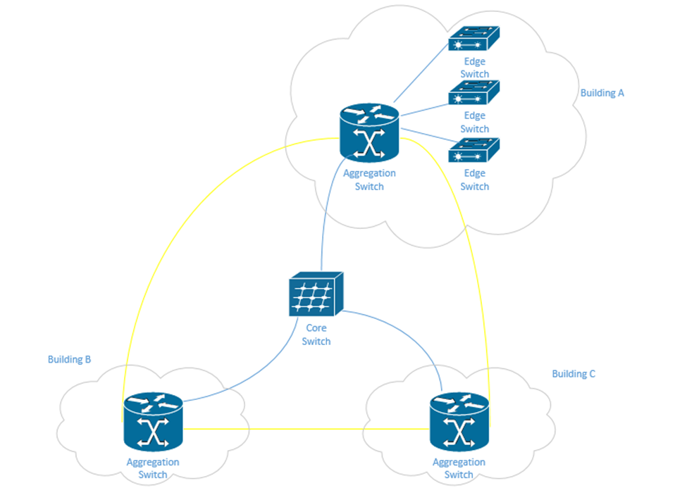
In a physically large network, having a single core switch would not be possible because it would require a data cable to be run from each part of the facility. In a small network, we may only have one or two layers of switches.
There may be redundant links between each set of switches. When we design our network, we should think about the amount of traffic passing through each switch and between the switches. Ideally, most traffic moves between different devices on the same set of access switches.
The second type of network is a Spine-Leaf. A spine-leaf network can scale better than a three-tier network. Typically, a Spine-Leaf network contains two layers of switches – the Leaf layer connects directly to user devices, while the Spine connects directly to Leaf switches only. No leaf switch connects to another and no spine switch connects to another. We can enlarge the network by adding more spines and more leaves.
A leaf can connect to multiple spines. If the network is small, the leaf might connect to all the spines. Otherwise, it may only connect to some of the spines. The spine is known as the backbone. The path that the traffic takes (which spine a leaf chooses to send fabric to) is chosen at random. This ensures that no spines become overloaded. If a spine fails, the network will continue to function.
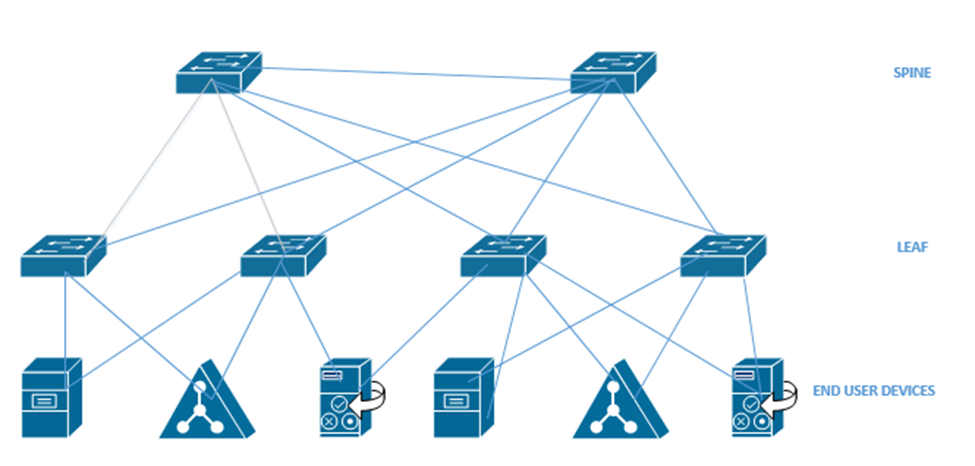
When we have a data center with multiple racks, we might decide to install a switch at the top of each rack. This is known as top of rack switching. The switch at the top of the rack is an edge switch and provides access to the devices in the rack. It connects back to an aggregation switch (or to multiple spine switches if we are using the spine-leaf configuration).
In a software-defined network, we don’t have to worry as much about the physical infrastructure. In other words, in a traditional network, each network device has to be programmed separately, and each network device makes independent decisions about how to forward traffic. In an SDN, control of the network is separate from the physical infrastructure.
We create a set of rules that the software then implements across the entire network.
We can think of the SDN as a set of layers
- Application Layer – the application layer contains the rules that manage the network and forward traffic. We create rules in the application layer.
- Control Layer – the control layer connects the application layer to the infrastructure layer. The connection between the controller and the application is called the Northbound interface. The connection between the controller and the infrastructure layer is called the Southbound interface.
The controller takes information from the application layer and translates it into the actual commands that the infrastructure layer will use to forward traffic. - Infrastructure Layer – the infrastructure layer contains the physical devices that are connected. These devices forward traffic based on information given to them by the control layer. The network’s actual capacity is limited to what the infrastructure layer can provide. The infrastructure layer may take the form of a Spine-Leaf or Three-Tier, but usually takes the form of a Spine-Leaf.
- Management Plane – the management plane contains the configuration information for the network. It is separate from the plane that contains the data being forwarded.
- Data Plane – the data plane contains the data that the network is forwarding.
Traffic moving up from the infrastructure layer to the application layer is considered moving “north” while traffic moving from the application layer down to the infrastructure layer is moving “south”. Traffic moving between devices is considered moving East-West (i.e. from server to server).
The next topic we will look at is where we should put our data center and/or server infrastructure. There are four options.
- Branch Office – If we have an organization with several offices, we can group them into branch offices and head offices. The branch offices are smaller. A branch office is one that might be too small to have dedicated infrastructure. It might have a “branch router” and connect back to the main office via a WAN or a VPN. We might store our main servers in the head office, but users can still access them via the WAN or VPN.
- On Premise – We can build a data center in our office. It can be a separate room or separate building. A good data center has multiple internet connections to manage incoming and outgoing connections, battery back up for power, and redundant power supplies. It may also have security and Before we build a data center we must consider
- Whether we have enough equipment to justify the cost of the construction
- The cost of cooling the data center.
- The cost of powering the data center
- Whether we have dedicated staff to operate the data center
- Whether we have adequate internet connections to support the data center
- Whether the function of the infrastructure and the data is too sensitive to outsource to a third party
- Whether we have enough equipment to justify the cost of the construction
- Colocation – If we can’t justify the cost of an on-premise data center, we might outsource it to a colocation. A colocation is where another organization builds a data center and rents out portions of it to other customers. The colocation may charge a flat rate per square foot or per rack unit. The colocation may provide internet connectivity or may require us to provide the connectivity. We are responsible for supplying, installing, and maintaining all of the equipment at the colocation.
- Cloud – The cloud is where we outsource our infrastructure to a third party. We don’t have to worry about the infrastructure, internet, electricity, or physical devices. We will learn more about the cloud in the next section.
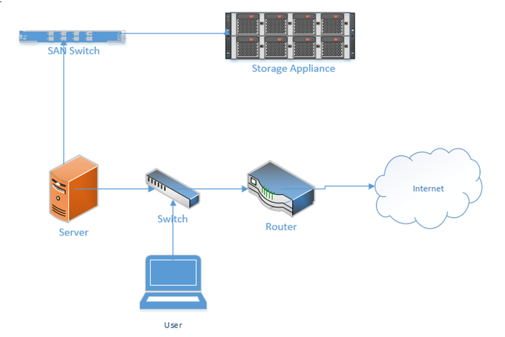
The last topic covers Storage Area Networks or SANs. When you buy a computer, it will come with a hard drive, which hopefully will have enough capacity to store your data. When you buy a server, it might come with several hard drives, which will hopefully have enough capacity to store your data. What happens when you have too much data and not enough storage capacity? You can buy more servers, but servers are inefficient for storing large volumes of data. Why? A server has other expensive components such as processors and RAM, which are good for processing data. When the purpose of the server is to just store data, we end up wasting money on the other hardware. Servers also usually have limited network connections that can become overloaded.
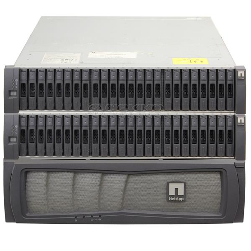
The solution? A storage appliance. A storage appliance is like a giant box with a large data storage capacity. In reality, it is a special-purpose server with many hard drives. Its only purpose is to store data. When connected to a network, the storage appliance will allow multiple users to store their data on it. We can create multiple “virtual” drives on the storage appliance, each of which can span multiple physical drives. A user or server can connect to a virtual drive on the network almost in the same process as if it were physically connected to his computer.
A popular storage appliance is the NetApp. It’s basically a box of hard drives. It’s more complicated than that, but entire books have been written on storage appliances.
A Storage Area Network uses some of the same principles as an ethernet network. A server might connect to both a normal ethernet network (for communicating with users) and a storage area network (for communicating with the storage appliances).
Some concepts
- A Host Bus Adapter or HBA is like a network interface card. It connects the server to the storage area network. The HBA operates on the first layer, known as the Host Layer.
- A SAN Switch is like an ethernet switch, but it forwards traffic between devices on the storage are network
- We call the SAN network devices (switches, routers, and cables) the fabric
- Each device in the SAN has a hardcoded World-Wide Name (WWN) which is like a MAC address in the ethernet world. The switch uses the WWN to route traffic between devices. The switch operates on the second layer, known as the Fabric Layer.
- Switches and HBAs don’t understand what files are. They only see data moving as “blocks”, or groups of 0’s and 1’s.
- SAN networks can operate over copper or fiber links
- The third layer is known as the Storage Layer.
- Each storage appliance is assigned a unique LUN or Logical Unit Number. A storage appliance is a box of hard disk drives. We can subdivide a storage appliance into multiple partitions and assign each partition a unique LUN.
- Each server (or device that can read from or write to a storage appliance) is assigned a LUN.
- We can use the LUN to restrict access from specific servers to specific storage locations. The storage appliance maintains an access control list, which determines (on a LUN by LUN basis) which devices can access each of the storage appliance’s LUNs.
There are many network protocols that can be used for communicating over a SAN
- FCoE or Fiber Channel over Ethernet
- Fiber Channel Protocol
- iSCSI
- SCSI RDMA Protocol
The SAN does not provide “file level” storage, only “block level” storage. That is, a server can’t call up the storage appliance and say something like “give me the file called DraftProposal.docx”, because the storage appliance doesn’t know what files are.
Instead, SAN says to the server, “here is a bunch of storage space, do what you want with it”. The server says, “here is a bunch of data in the form of 0’s and 1’s, put them there, there, and there”. The server must be able to manage the file system. When a user asks the server for the file DraftProposal.docx, the server asks itself “where did I put DraftProposal.docx…oh yeah…I put there, there, and there?”. The server treats the storage appliance like its own hard drive. It may create a file allocation table on the storage appliance to help itself find files.
In a less-complicated environment, we could use a NAS or Network Attached Storage device. Like a storage appliance, a NAS is a box of hard disk drives. But unlike a storage appliance, a NAS connects to the ethernet and provides file level storage. A NAS is more like a server that can store data (and does nothing else).
Some protocols that can be used with a NAS
- Apple File System
- Network File System
- FTP
- HTTP
- SFTP
- Server Message Block
Let’s dig deeper into the storage appliance’s connections.
If we didn’t want to build out a separate storage area network, we could use FCoE or Fiber Channel over Ethernet to transmit all our storage data on our existing ethernet network.
FCoE uses 10 Gbit Ethernet to communicate. Just like ethernet, fiber channel uses frames to communicate. When transmitted over FCoE, each fiber channel frame is encapsulated (packaged) inside an ethernet frame, transmitted to the recipient, and then deencapsulated by the recipient.
Each device connected to an ethernet network must have its fiber channel name mapped to a unique MAC address, so that the ethernet network knows where to deliver the data. This can be completed by a converged network adapter or CNA. A CNA is a device that contains a host bus adapter and an ethernet adapter.
A Fiber Channel network communicates between 1 Gbit/s and 128 Gbit/s via the Fiber Channel Protocol. We can create the following types of connections
- Point-to-Point: two devices communicate with each other through a direct cable connection
- Arbitrated Loop: devices are connected in a loop. The failure of a single device or link will cause all devices in the loop to stop communicating. This connection type is no longer used.
- Switched Fabric: devices are connected to a SAN switch. The fabric works like an ethernet network and can scale to tens of thousands of devices.
There are five layers in fiber channel
- The Physical Layer (Layer 0), which includes the physical connections
- The Coding Layer (Layer 1), which includes the transmission/creation of signals
- The Protocol Layer, known as the fabric (Layer 2), which transmits the data frames
- The Common Services Layer (Layer 3), which is not currently used but can be used for RAID or encryption if the protocol is further developed
- The Protocol Mapping Layer (Layer 4), which is used by protocols such as NVMe and SCSI
We use SFPs, SFP+s, and QSFPs with fiber optic cables to connect the various devices in a Fiber Channel network.
iSCSI or Internet Small Computer Systems Interface is another network protocol that allows storage devices and servers to communicate. iSCSI operates over the existing ethernet network without the need for special cabling or adapters. We typically use iSCSI for two purposes
- Centralize our data storage to one or several storage appliances
- Mirror an entire data storage appliance to an appliance in another location to protect in the event of a disaster
The different iSCSI devices
- Initiator. An initiator is a client device such as a computer or server. A software application or driver sends commands over the device’s ethernet adapter in the iSCSI format. For faster communications, a hardware iSCSI host bus adapter can be used.
- Target. A target is a storage device such as a server or storage appliance. A device can be both an initiator and a target.
- Like Fiber Channel, each device is given a LUN or Logical Unit Number.
Some features of iSCSI
- Network Booting. A device can boot from a network operating system and then access an iSCSI target to store and retrieve its data. When the computer boots, instead of looking at its hard disk for the operating system, it contacts a DHCP server that contains a boot image of an operating system. The DHCP server uses the device’s MAC address to forward it to the correct iSCSI device. The iSCSI drive is then mounted to the computer as a local drive.
- iSCSI uses ports 860 and 3260
Security Problems
- iSCSI devices authenticate via CHAP by default but can use other protocols. CHAP is not secure. We will learn more about CHAP later.
- iSCSI devices can be connected over a VLAN so that they are logically isolated from unauthorized users or devices. If we automatically trust all the devices on the VLAN, then a compromised device can gain access to the entire system.
- iSCSI devices can be connected over a separate physical network. If we trust all devices on the physical network, then a compromised device can gain access to the entire system.
- An eavesdropper can spy on the data being transferred over the iSCSI network if the data is not encrypted (and it frequently isn’t).
InfiniBand is another storage area network connection format. InfiniBand is typically used by supercomputers that need a very high level of data transfer and a low latency. It can support transfer rates of up to 3000 Gbit/s. It uses QSFP connectors and copper or fiber cables.
We can also transfer Ethernet over an InfiniBand network.