
2.1 Compare and contrast various devices, their features, and their appropriate placement on the network
- Networking Devices
- Layer 2 Switch
- Layer 3 Capable Switch
- Router
- Hub
- Access Point
- Bridge
- Wireless LAN Controller
- Load Balancer
- Proxy Server
- Cable Modem
- DSL Modem
- Repeater
- Voice Gateway
- Media Converter
- Intrusion Prevention System (IPS) / Intrusion Detection System (IDS)
- Firewall
- VPN Headend
- Networked Devices
- Voice over Internet Protocol (VoIP) Phone
- Printer
- Physical Access Control Devices
- Cameras
- Heating, Ventilation, and Air Conditioning (HVAC) Sensors
- Internet of Things (IoT)
- Refrigerator
- Smart Speakers
- Smart Thermostats
- Smart Doorbells
- Industrial Control Systems / Supervisory Control and Data Acquisition (SCADA)
Now that we know a bit about how devices communicate and a bit about the wiring, let’s think about all the different devices we need to set up a network. The first device is a firewall.
A firewall monitors and filters traffic on a network.
A firewall sits between the internet (WAN) and the local network (LAN). A firewall could also sit between different segments of a LAN. For example, a firewall could sit between a group of servers and the remainder of the network.
A firewall could be hardware-based or software-based. A firewall could be a component of a larger network device such as a router. In a large organization where a great deal of traffic passes through the network, a large, hardware-based firewall must be installed. Firewalls are rated based on the volume of traffic that they can handle. Of course, more complicated configurations can reduce the amount of traffic that a firewall can handle. If the firewall has to evaluate ten rules per packet, it will operate faster than if it has to evaluate one-hundred rules per packet.
Common firewall brands include
- Sonicwall
- Cisco ASA (Adaptive Security Appliance)
- Fortigate
- Cisco Meraki MX
Configuration of a firewall may be
- Through a console (requiring special commands)
- Through a web-based GUI or software-based GUI
- Automatically through the cloud, which is useful for organizations that deploy dozens, hundreds, or thousands of devices
An organization may select a firewall brand based on their existing network infrastructure. For example, if the customer uses Cisco switches and routers in their network, they may choose to install Cisco ASA firewalls as well.
There are four components to a firewall configuration
- ACL or Access Control List. The Access Control List is a set of rules for what traffic is permitted to pass and what traffic is not permitted. There are many types of rules, based on
- Source IP address. Where is the traffic coming from? The source IP address could be on the LAN or on the WAN. It could be a specific IP address or a range of addresses.
- Destination IP address. Where is the traffic going? The destination IP address could be on the LAN or on the WAN. It could be a specific IP address or a range of addresses.
- Source Port Number. What is the port number of the source traffic? The source port could be on the LAN or on the WAN. It could be a specific port or a range of ports.
- Destination Port Number. What is the port number of the destination traffic? The destination port could be on the LAN or on the WAN. It could be a specific port or a range of ports.
- Username. Access Control Lists can be user-based. Permissions can be granted or denied to specific users based on their needs in the organization. For example, guests can be permitted to access only the internet and not resources such as remote desktop or SQL servers.
- Rules can be specific or could combine a combination of parameters
- For example, a rule could say ‘Allow traffic from 10.1.1.1, port 5 to the range of IPs 192.168.3.0 to 192.168.3.255’. All traffic received from 10.1.1.1 port 5 will be permitted to access destinations in the range of 192.168.3.0 to 192.168.3.255. Traffic from other source IP addresses and/or ports will be rejected. Traffic from 10.1.1.1 to destinations outside of 192.168.3.0 and 192.168.3.255 will be rejected.
- Always Allow. An Always Allow rule allows all traffic matching a rule. For example, “always allow traffic from the source IP 10.1.1.1”. All traffic from 10.1.1.1 will be permitted regardless of the port number or destination.
- Always Deny. An Always Deny rule denies all traffic matching a rule. For example, “always deny traffic from the source IP 10.1.1.1”. All traffic from 10.1.1.1 will be denied regardless of the port number or destination.
- For example, a rule could say ‘Allow traffic from 10.1.1.1, port 5 to the range of IPs 192.168.3.0 to 192.168.3.255’. All traffic received from 10.1.1.1 port 5 will be permitted to access destinations in the range of 192.168.3.0 to 192.168.3.255. Traffic from other source IP addresses and/or ports will be rejected. Traffic from 10.1.1.1 to destinations outside of 192.168.3.0 and 192.168.3.255 will be rejected.
- Order of Operations
- A firewall could have dozens or thousands of rules. The rules are ranked in order of priority.
- When the firewall receives a piece of traffic, it starts checking the rules in order until it finds one that matches the traffic’s source and destination. It then applies that rule to the traffic.
- The firewall will only apply one rule to a piece of traffic. Once that rule is applied, the firewall stops checking additional rules.
- It is important to put the rules in logical order so that traffic is not accidentally accepted or rejected. When a firewall receives a piece of traffic that does not match any rules, it will either allow or reject the traffic based on its configuration.
- Many firewalls are preconfigured with two default rules
- Always allow traffic with a source inside the network (LAN)
- Always reject traffic with a source outside the network (WAN)
- Always allow traffic with a source inside the network (LAN)
- The two default rules should be put at the bottom of the list.
- The first rule (allowing all traffic from inside the LAN) is dangerous because users cannot be trusted to access only safe resources on the internet. It should be modified (broken down) into two rules.
- Always allow traffic with a
- Source inside the network (LAN)
- Destination outside the network (WAN)
- Limited to specific ports outside the network (port 80, port 443, port 3306, etc.). The specific ports should be based on resources that users need to access.
- Source inside the network (LAN)
- Always deny traffic
- Source inside the network (LAN)
- Destination outside the network (WAN)
- This rule applies second; any traffic not matching the previous rule will be denied
- Source inside the network (LAN)
- Always allow traffic with a
- The first rule (allowing all traffic from inside the LAN) is dangerous because users cannot be trusted to access only safe resources on the internet. It should be modified (broken down) into two rules.
- A firewall could have dozens or thousands of rules. The rules are ranked in order of priority.
- Source IP address. Where is the traffic coming from? The source IP address could be on the LAN or on the WAN. It could be a specific IP address or a range of addresses.
- Application-Based vs Network-Based
- An application-based firewall will analyse traffic on a deeper level than a network-based firewall
- The network-based firewall looks at traffic source and destination IP addresses, but the application-based firewall also looks at its contents
- The application-based firewall looks at the content of each packet before applying a rule.
- An analogy is a person who is screening mail. A network-based firewall would look at the to and from addresses on the envelope before deciding whether to forward the mail. An application-based firewall would open each envelope and look at the contents before deciding whether to forward the mail.
- Application-based firewalls can slow down traffic because they are analyzing the contents of each packet, which takes longer.
- An application-based firewall will analyse traffic on a deeper level than a network-based firewall
- Stateful vs Stateless
- Consider that almost all traffic on the internet is two-way traffic. When a user downloads a file from the internet, that file download is two-way. The downloader’s computer first makes a request to the server hosting the file (the sender). The sender’s computer breaks the file into packets and sends them one at a time. Each time the downloader’s computer receives a packet, it acknowledges receipt by sending a message. This is known as a connection (from TCP/IP).
- One party is responsible for originating each connection. In this case, the person who downloaded the file originated the connection (the person who is inside the network).
- A stateless firewall applies rules based only on the source and destination IP addresses and ports of the packets, but a stateful firewall will identify which party originated the connection (whether that party was inside the network or outside), and then block or allow it based on the source. A packet that is normally permitted or denied by an ACL may be denied or permitted by a stateful firewall.
- A stateful firewall requires additional hardware to process the decision making.
- Consider that almost all traffic on the internet is two-way traffic. When a user downloads a file from the internet, that file download is two-way. The downloader’s computer first makes a request to the server hosting the file (the sender). The sender’s computer breaks the file into packets and sends them one at a time. Each time the downloader’s computer receives a packet, it acknowledges receipt by sending a message. This is known as a connection (from TCP/IP).
- Implicit Deny
- As mentioned previously, a firewall lists its rules in order and applies the first rule that matches the traffic
- If the traffic does not match any rule, the firewall should deny it
- This is known as “implicit deny”
- The last rule in the list should be to deny all traffic
- As mentioned previously, a firewall lists its rules in order and applies the first rule that matches the traffic
Cloud-Based Firewalls
Newer firewalls such as Fortigates and Cisco Meraki MX Series routers connect to the cloud. The cloud allows them to
- Automatically receive firmware updates
- Automatically download and update their configuration (and allow an administrator to configure multiple devices at the same time)
- Share threat intelligence data, even across organizations. For example, if a firewall detects a threat, it can upload the data to the cloud, where it is shared by many firewalls across the organization.
NGFW/Layer 7 Firewall
A NGFW or Next Generation Firewall, also known as a Layer 7 Firewall, is part of the third generation of firewalls. It can perform deep packet inspection and can be combined with a RADIUS server, quality of service management, and website filter.
Why do we need a NGFW? Security threats are becoming more complicated. The traditional firewall rules block traffic to/from specific addresses and ports. That’s not good enough anymore, because bad traffic can come in disguised as good traffic. Legitimate, trusted devices can become infected and used to launch attacks. The NGFW can look inside the traffic – not just at its source or destination – to decide whether it is legitimate.
An NGFW can also verify the identity of the user sending or receiving the traffic.
Router
A router connects two or more networks together. A router receives packets of data (from inside and outside the network) and then decides where to forward the packets to.
A router will contain a routing table (a set of static routes), which tell it where to send data based on the subnet of its destination address. In a simple setup, a router may only have one destination to send data to.
The most common type of router security is an ACL or Access Control List. An ACL is a list of source subnets (networks) and their permitted destinations. Like a set of firewall rules, an ACL check each data packet against the ACL and apply the first rule that matches.
A rule can be “always allow” or “always deny”. For example
- Always deny traffic from addresses in the range of 252.252.252.0 to 252.252.252.255
- Always allow traffic from 192.168.2.1
A rule can apply to one or more router interfaces and to one or both directions. Each router manufacturer may have a different scheme for configuring a router ACL, but the concept is the same.
Router antispoofing is a process to prevent fake routers from joining the network. Remember that a rogue user could connect his own router to the network and attempt to route the traffic somewhere else.
More advanced routers such as Cisco ISRs can also perform some of the following functions
- DHCP server
- DNS Server
- VoIP controller
- Wireless controller
Consider an unfortunately common situation where a rogue or clumsy user connects a router to a network that already has a router. Devices on the network are already configured to communicate with the existing router and will likely ignore the new one, so not much data will flow to it. But if a rogue router is also acting as a DHCP server, then when the DHCP lease expires on any network clients, they may contact the new router for a new IP address. The rogue router will also provide a different default gateway (its own) and begin to intercept traffic.
How to prevent rogue routers? Enforce MAC filtering and other security measures on network switches as discussed further in this section.
Does the router sit behind the firewall or does the firewall sit behind the router? Which of the below scenarios is correct? Either can be correct and network administrators have been debating this issue.
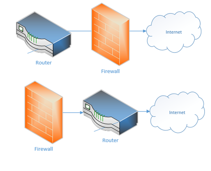
If the firewall sits between the internet and the router, it can protect the router from attacks. But if the router sits at the edge of the network, it can better communicate with external devices. Sometimes you don’t even need a separate physical router because a single device can handle all the functions – firewall, DHCP, DNS, etc.
The basic configuration of the router
- Set up a username/password, other credentials to monitor and access the router
- Identify the type of internet connection that you have, and whether the IP address is DHCP or static. Assign the correct static IP address to each WAN port if necessary
- On the LAN side, set up the scope of the LAN. What class of network will you use? Set up DHCP.
- Add routes or let the router automatically create routes.
- Create security rules
- Set up other features such as a firewall if applicable
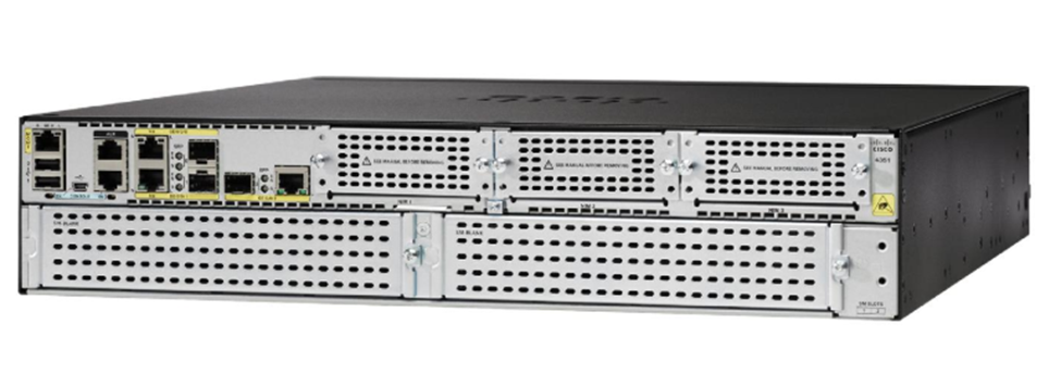
Some Cisco routers are known as Integrated Service Routers (ISR). If we look at the left side of this ISR, we can see several standard ethernet ports and a few SFP ports. These ports allow us to connect WAN connections (ethernet or fiber if we use an SFP). We can also connect USB-based cellular modems using the USB ports.
On the right side of the router, and on the bottom are panels that can be removed. We can add different modules to this router that give it additional features (such as switching, connections to more advanced internet connections, and VoIP services).
Some of the modules we can add
- An FXO card that allows us to connect analog phone lines to the router
- An FXS card that allows us to connect devices such as fax machines and other devices that require analog phone lines
- An EHWIC card that allows us to connect a T1 internet connection to the router
- A switch module that allows us to connect up to 24 ethernet-based devices directly to the router. This turns the router into a router and a switch
Switch
A switch connects multiple devices on the internal network. We install the switches after the router.
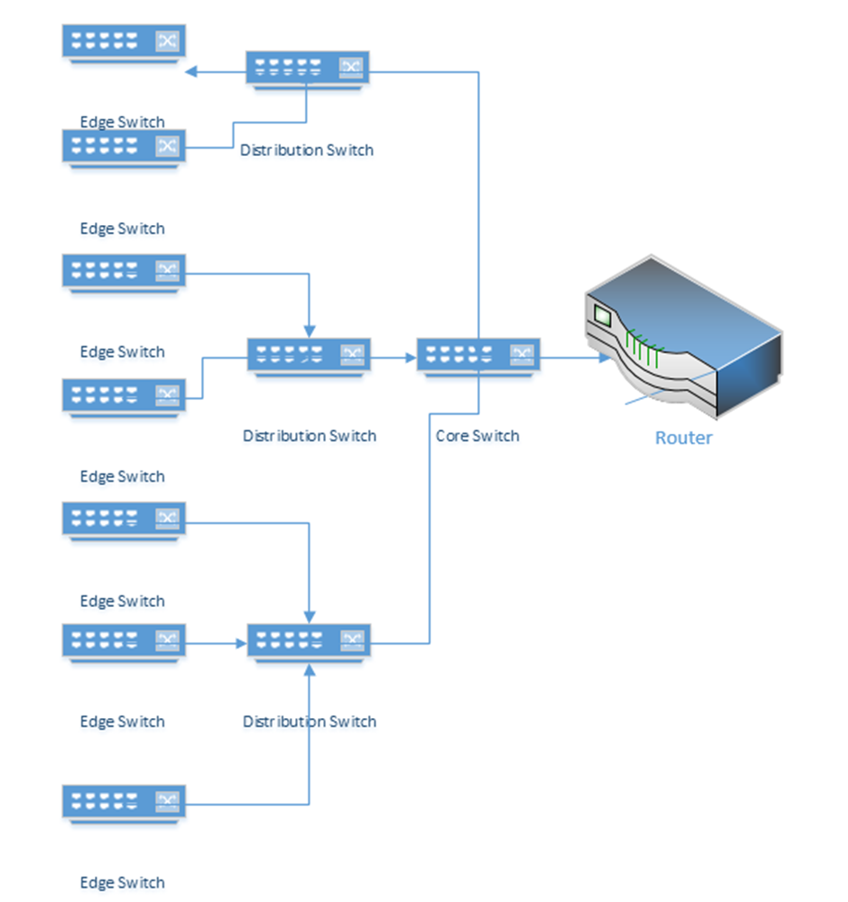
In a larger network, switches can be distributed in a hierarchy such as a three-tier or a leaf topology.
It is recommended for any switch that the following security measures are taken during initial configuration
- Create a separate, unused VLAN and shut it down
- Move all unused ports to the unused VLAN
- Shut down all unused ports
- On a physical security level, unused patch panel ports should not be physically patched in to the switch. An exposed data jack can permit a user to connect a device which should not otherwise be connected.
Switches also employ MAC address filtering, which is rarely enabled by administrators in practice (but should be)
- The switch knows the MAC address of every device on every port. This data goes to a MAC address table.
- Once a network is set up, and devices are connected to a network switch, an administrator will have a list of device MAC addresses on the network.
- The administrator can configure the switch to block devices with MAC addresses different from the ones on the list.
Typical switches are “layer two” in the OSI model; that is, they can only forward data frames on the same subnet. Data outside the subnet must be forwarded to a router, even if multiple subnets are connected to the same switch. A layer three switch acts as a router in that it can forward traffic between different VLANs. Layer three switches have additional security settings, including Access Control Lists.
Switches also provide the following security features
- Spanning Tree Protocol which prevents loops between two switches. If a switch detects a loop, it shuts down one of the ports.
- Flood Guard. A flood occurs when a switch receives a large amount of traffic on a single port. Like many other electronic devices, a switch has a buffer. The buffer stores received data that the switch is waiting to process. A hacker could attempt to bypass a switch’s security measures by sending a large amount of traffic and overflow the buffer.
- Newer switches have security settings in place that can drop additional traffic or shut down the ports when flooded.
I might connect my network like the following diagram (this is common in some corporate networks)
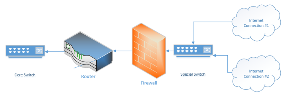
What’s up with the “special switch” that sits between the internet connections and the firewall? If I bought multiple internet connections for redundancy, but I only have one WAN port on my router or firewall, then I can connect the internet connections to a switch. The router/firewall and internet connections sit in the same subnet on the special switch. If we need to failover from one internet connection to another, we can do so through the switch.
Sometimes an ISP will provide a switch as part of their customer premises equipment. Instead of connecting to the ISP’s router or modem, you to connect to the ISPs switch. An ISP uses a switch for traffic shaping, monitoring the quality of the internet connection, delivering an ethernet WAN connection.
Hub
A hub is like a switch except that it doesn’t remember the MAC address of any device that is connected to it. When a hub receives a frame, it floods it out of all its other ports. It doesn’t think about who needs to receive it (or which ports to send it out of). This results in frequent collisions because other devices connected to the hub may be trying to send data to it. The data that the user devices send may collide with the data that the hub is sending.
Hubs can be found in older networks, but they have been largely replaced by switches. A hub performs most of the same basic functions as a switch, in other words, moving traffic between internal network devices. A hub doesn’t understand subnets either.
Multilayer Switch
Remember that a switch works on Layer 2 to route frames between devices on the same subnet. A device isn’t supposed to be able to send traffic to a device on another subnet. What if I have multiple subnets but I don’t want to set up multiple physical switches (one for each subnet)? I can create what is called a VLAN (Virtual Local Area Network).
We can assign each port on the switch a VLAN. If devices are connected to the correct port, then the switch can then enforce the VLAN rule. In order for a device on one VLAN to talk to a device on another VLAN, it must send the traffic to the router.
A Multilayer Switch, also known as a Layer 3 Switch, can route traffic between different VLANs without the use of a router. A switch may also be able to operate on Layer 4; the transport layer. It can decide based on the
- MAC Address (in a frame)
- Protocol (in a frame)
- IP address (in a packet)
- Protocol (in a packet)
- Port number (on layer 4)
The benefit of installing a Layer 3 switch is that packets travelling from one VLAN to another do not have to travel to a router. If we used a Layer 2 switch and a router, this setup is known as a Router on a Stick, or ROAS, because the router is physically connected to a switch over one cable (on a trunk port – a trunk port is a port that has access to all of the VLANs). A data packet travelling from VLAN 1 to VLAN 2 for example, travels from the top device to the switch, to the router, back to the switch and then out to the middle device.
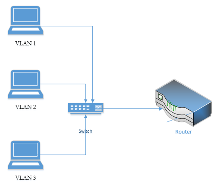
If we replace the switch with a multilayer switch, then we don’t need the router (except to communicate with external networks). A layer 3 switch decreases latency because packets travel a shorter distance.
A Layer 4 switch takes a deeper look at the traffic before forwarding it. It can check the port number (the virtual port numbers we talked about at the beginning of the book), not the physical port number. Thus, we can configure a switch to route traffic based on its type (HTTP, FTP, etc.) and prioritize traffic based on its content, not just its destination/source.
A switch can make routing decisions based on the Layer 5, 6, or 7 content of a packet. These switches are called content switches. Common applications of a Layer 7 switch are load balancing and content delivery.
Bridge
A network bridge is a device that connects two networks to act like one network. A bridge is different from a router, which connects two separate networks.
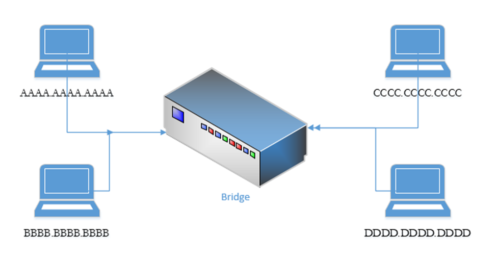
Consider a network with two devices, having MAC addresses, connected to the bridge on port 1
AAAA.AAAA.AAAA
BBBB.BBBB.BBBB
And another network with two devices, having MAC addresses, connected to the bridge on port 2
CCCC.CCCC.CCCC
DDDD.DDDD.DDDD
The bridge connects the two networks together. A network bridge works like a network switch in that it records MAC addresses of packets arriving on each port. For example, if device AAAA.AAAA.AAAA sends a network packet to device DDDD.DDDD.DDDD, the network bridge learns that device AAAA.AAAA.AAAA is on Port 1.
The bridge does not know the location of the other three devices, so it floods the both ports with the packet intended for DDDD.DDDD.DDDD. When DDDD.DDDD.DDDD responds, the bridge learns that it is located on port 2. Eventually, enough traffic passes, and the bridge learns the location of all of the devices. This is a simplified example as a network may contain hundreds or thousands of devices.
The bridge will eventually learn that AAAA.AAAA.AAAA and BBBB.BBBB.BBBB are on the same segment, and will not forward traffic from AAAA.AAAA.AAAA to BBBB.BBBB.BBBB. In reality, the traffic from AAAA.AAAA.AAAA to BBBB.BBBB.BBBB will not reach the bridge because a properly functioning network switch installed before the bridge will direct the traffic to BBBB.BBBB.BBBB appropriately. A switch on the same network segment as the bridge will have the same MAC address information as the bridge.
Bridges are not common as their functions are typically handled by switches or routers. A bridge can connect more than two network segments at the same time.
An example of a bridge is a point-to-point antenna such as Ubiquiti AirFiber, which allows a bridge to be established between two separate buildings without any wiring. It uses a radio signal.
For example, consider a car dealership having a central show room with network equipment. The dealership has installed IP surveillance cameras on the light poles surrounding the parking lot. The dealership was able to power the cameras through the electrical connection on the poles, but the cost of running data cable to each pole from the central show room was too high. The cameras must be on the same network as the central show room. The solution is to bridge these cameras with the central show room through point-to-point antennas.
Modem
A modem sits at the edge of a network. Typically, a modem is supplied and configured by an internet service provider. The modem is configured to connect to the ISPs network. It may require a username, password, or other parameters.
Some types of modems
- Dial up Modem, which operates over a phone line. The maximum speed is 56 Kbps
- DSL modem, which operates over a phone line, but provides speeds of up to 1.5 Mbps
- Cable modem, which operates over a coaxial cable, and provides speeds of up to 10 Mbps
- Fiber optic cable modem, which operates over a fiber optic cable, and provides speeds of up to 1 Gbps
- Cellular modem, which connects to a cellular network. The speed could vary with the cellular network, but could be up to 100 Mbps
Wireless Access Point
Wireless Access Points are dispersed throughout the network and connect to a switch or multiple switches (preferably a PoE switch).
An access point sends and receives traffic over one or more “WLANs” or Wireless LANs. Each wireless LAN can be mapped to a subnet (VLAN). Each wireless network WLAN is associated with one or more SSIDs (multiple SSIDs can be associated with a single WLAN). The access point broadcasts SSIDs, which client devices can detect and connect to. An SSID can also be hidden. If an SSID is hidden, a client will be required to know its name to connect to it. In theory, hidden SSIDs can prevent hackers from connecting to the network, but SSIDs can be easily cracked.
An SSID can be configured as
- An open network, where any device can connect. This is a common setting for guest Wi-Fi.
- An encrypted network, requiring a user to enter a passphrase. There are several forms of encryption, discussed later.
- An encrypted network, authenticating through a username/password and RADIUS server/Active Directory server, or authenticating with a certificate.
An access point can be set up to
- Block connections from devices with specific MAC addresses. This is known as a blacklist.
- Allow connections only from devices with specific MAC addresses. This is known as a whitelist. We can create an open network, but only allow connections from devices with specific MAC addresses. In theory, this will work to prevent intruders without having to configure devices or provide passwords. A hacker can use a packet sniffer to intercept wireless data and then spoof the MAC address of a rogue device to match an authorized one.
Remember that every MAC address is unique and that it comes from the factory? Well, a hacker can change his! If a hacker knows the MAC address of a device that is authorized to connect he can change his and attempt to connect.
The signal strength of an access point should at least -70 dBm everywhere that Wi-Fi is required. A weaker signal will result in frequently dropped connections.
The two main Wi-Fi frequencies are 2.4 GHz and 5 GHz. Each of these bands is subdivided into channels. The 2.4 GHz band has 11 channels, and the 5 GHz band has 54 channels.
An access point will typically broadcast on both frequencies at the same time, but only one channel per frequency at a time. The channel
- May be preconfigured by the administrator and set permanently. The access point operates only on that specific channel.
- May be set so that the access point can choose a channel and change it when necessary.
- Two nearby access points should never broadcast on the same channel at the same time. If they do, signal interference will result, and no clients will be able to connect. Consider a network in an office building, with many access points. Signals from neighboring access points will interfere and cancel each other’s signals. Signals from access points on floors above and below will also interfere. Signals from rogue devices and mobile hotspots may also interfere. An access point may receive interference from dozens of devices at the same time and must therefore be able to select a specific channel that is free of interference.
Each access point comes with a built-in antenna. You can connect an external antenna to some access points. There are many shapes and sizes of antennas and the best antenna depends on the desired coverage area and signal strength increase required.
Special software such as AirMagnet Survey Pro or ekahau can be used to plan out wireless networks and optimize the placement of each access point. The signal strength of an access point can be affected (reduced by metal shelves, concrete walls, and other construction materials). The quantity of access points may need to be increased in densely occupied areas such as conference rooms and lecture theaters.
Access points can be fat or thin. A fat access point contains software to process the traffic whereas a thin access point sends data back to the controller.
Access points can be controller-based or standalone. When access points are standalone, each access point must be configured separately and operates independently. When there are multiple access points, a wireless controller is optimal. A controller
- Automatically configures access points based on a template; a controller can automatically detect and configure new access points
- Will optimize broadcast channel and power for each access point based on its traffic and signal-to-noise ratio
Cloud-based controllers and access points such as Cisco Meraki are available.
How do Wi-Fi networks detect collisions when they’re broadcasting data everywhere at the same time? In other words, if my laptop is sending data to the access point and the access point is sending data back to the laptop at the same time, the two signals will collide and cancel each other out. We use a system called the Distributed Coordination Function or DCF. If a wireless network device or access point tries to send a signal and determines that the recipient is busy, then it waits for some time before resending. Each device waits a random time to ensure that their signals do not collide a second time.
Media Converter
A Media Converter changes one form of media to another. Some media conversions include
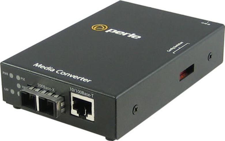
- Convert between a fiber optic signal and a copper ethernet signal. An ISP may need to transport a data signal long distances (where only fiber can carry it), but the network equipment at the customer site only supports copper. The media converter sits between the modem and the outside world, or between the modem and the customer’s equipment. An example of a media converter is below.
- Convert a POTS (Plain Old Telephone System) line into a digital signal and vice versa for a VoIP system. A device that does this is known as a Voice Gateway. Voice Gateways can include the Cisco Voice Gateway and Cisco ISR Routers with FXO cards. A voice gateway might be called an analog voice gateway.
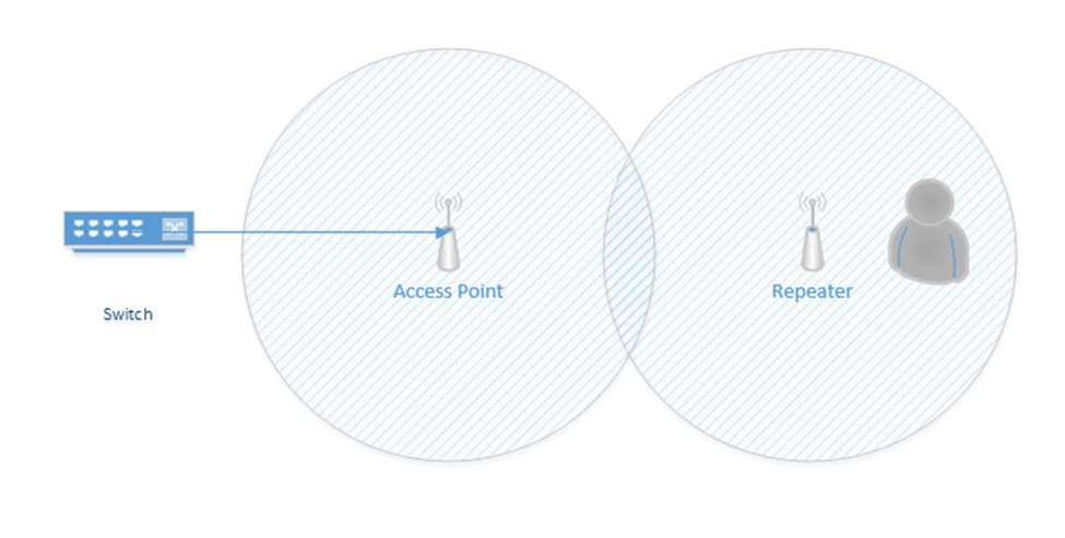
Wireless Range Extender
A wireless range extender is also known as a repeater. When placed at the edge of a wireless network, the range can be increased. Essentially, it repeats the signal that it “hears” from the nearest access point. It acts as a relay between the nearest access point and a device that is further away.
Consider the following scenario. On the left, I have an access point connected to a switch. Its range is shown by the circle around it. On the right, I have a user who wishes to connect, but is out of range. I don’t have the network infrastructure to install a second access point closer to the user.
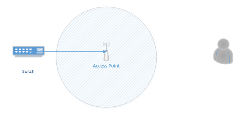
If I install a repeater, I now can extend the range of the access point to the user.
Wireless Controller
A wireless controller is a device that manages access points. The wireless controller may directly connect to each access point, or it may connect to a switch that is on the same subnet as the access points. We can place the controller anywhere on the network that makes sense, as long is the access points can logically reach it. It is typically installed in the MDF.
The controller uses the Control and Provisioning of Wireless Access Points Protocol, or CAPWAP. Cisco devices use the Lightweight Access Point Protocol or LWAPP.
The controller
- Monitors the status of each access point
- Updates the configuration of each access point
- Sends configuration to each new access point
- Updates the firmware of each access point
A controller might be cloud-based, such as Cisco Meraki.
A controller may be licensed for a specific number of access points. We should purchase a controller that can support the number of access points in use on our network.
Load Balancer
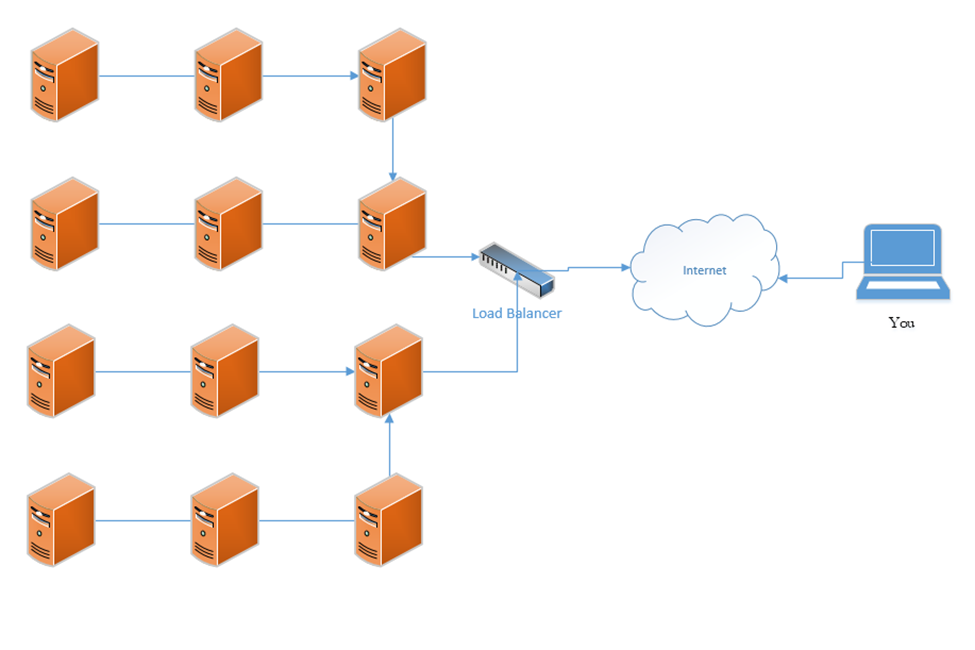
A load balancer distributes traffic among multiple resources. For example, consider that the Google.com website has only one URL (www.google.com), which would ordinarily point to one IP address. That IP address would ordinarily point to one web server. But one single web server would be overloaded by the traffic; in fact, the Google.com website has millions of web servers. The solution is to install a load balancer in front of those servers. The load balancer can distribute the incoming traffic among all the web servers.
DNS load balancing is when a domain name’s DNS records point to multiple web servers. For example, Google.com’s DNS records could point to both 11.11.11.11 and 12.12.12.12, each of which is assigned to a separate server. This would balance the traffic among two servers (which is not enough for Google). Attempting to balance millions of servers on one DNS record would not work because the customer would not have enough public IP addresses to cover all the servers in use, and the DNS record would be massive.
A load balancer uses a scheduling algorithm to determine how to distribute traffic among the servers connected to it. Consider a scenario where there is one load balancer and three servers, Server A, Server B, and Server C. There are several types of load balancing algorithms
- First Come First Served – each request is handled in the order that it arrives; when the servers are busy then additional requests are put on hold. The load balancer sends the first request to Server A, the second request to Server B, and the third request to Server C. The load balancer does not send additional requests to the servers until a server indicates that it has spare capacity (i.e. that it has completed the current request).
- Round-Robin – each request is handled in the order that it arrives. The load balancer sends the first request to Server A, the second request to Server B, and the third request to Server C. The fourth request is sent to Server A, the fifth request is sent to Server B, and so on. The round-robin algorithm assumes that all the servers have the same capacity, and that all requests are of the same size. If some requests take a server longer to process, they could overload the servers. If one server is more powerful then the rest, it could remain idle for extended periods of time (since all servers receive the same number of requests).
- Weighed Round-Robin – like round robin, but each server is given a specific weight based on its capacity. For example, if server A is twice as powerful as Server B or Server C, it can be given a weight of two, while Servers B and C are each given a weight of one. Server A would then receive twice as many requests as Server B and Server C.
A sticky session allows a load balancer to remember each client (based on their HTTP session). When a returning client is recognized, the load balancer sends that client back to the same server that they were previously connected to, regardless of the server load. This allows the server to maintain the client’s data locally (and not in a central database). This is also known as affinity.
Load balancers typically work in pairs or groups. This prevents the load balancer from becoming a single point of failure.
In a logical network topology, the load balancer is shown to be connected between the internet and the servers that it is balancing. In the physical reality, the load balancer can be connected anywhere on the network. If a load balancer has 1000 servers connected behind it, it wouldn’t have 1000 physical connections to those servers, but instead would route traffic to them over the local network. Regardless of the load balancer’s location, it must have a good network connection, typically 1 Gbps or 10 Gbps.
The group of servers connected to the load balancer can be active-passive or active-active. In an active-active configuration, the load balancer distributes the work among all the connected servers. In an active-passive configuration, some servers remain active (receive work) and some remain passive (do not receive work). In the event of a failure of one of the active servers, a passive server is activated and begins to receive work.
An active-active configuration is better because it can quickly respond to surges in traffic and allows the system to fully utilize all its resources.
In a Virtual IP scenario, the load balancer does not exist. Instead, all the servers work together to share the workload. Consider that we have three servers:
Server A has a private IP of 10.0.0.1
Server B has a private IP of 10.0.0.2
Server C has a private IP of 10.0.0.3
The public IP address is 11.11.11.11
Servers A, B, and C communicate with each other over their private IPs 10.0.0.1, 10.0.0.2, and 10.0.0.3. The servers all set 11.11.11.11 as their public IP, and then elect one server to respond to requests. For example, Server A, B, and C choose to have Server B respond to all requests on 11.11.11.11. If Server B is overloaded, it may communicate this fact with Server A and C (over their private IPs), which designate Server A to temporarily respond to requests on 11.11.11.11.
The servers continually ping each other to ensure that all the servers are functional. This form of communication is known as a heartbeat. If Server B were to stop responding within a specific period, Server A and Server C would choose to designate Server A to respond to new requests.
The algorithm used to determine which server would respond will vary from scenario to scenario.
IDS/IPS
An IPS (also known as a NIPS) is a Network-Based Intrusion Prevention System, and an IDS (also known as a NIDS) is a Network-Based Intrusion Detection System.
A NIDS can only detect unauthorized access, but a NIPS can detect and react to the unauthorized access.
Why bother with a NIDS if it doesn’t stop bad traffic? Every device has “false positives”. A false positive is when the NIDS/NIPS falsely marks legitimate traffic as illegitimate. A NIPS can also slow down a network, if it can’t screen traffic as fast as it is passing through.
A NIDS can flag what is bad but let it through. A network administrator can investigate the traffic later and if it is bad, he can update the firewall based on what he found.
A NIPS can block all the traffic that it thinks is bad. If users complain, the network administrator can investigate later.
As a network administrator, you may think a NIPS is better. But a large organization may not be able to afford a drop-in productivity associated with blocked traffic. It may choose to take the risk of letting everything through (even the bad stuff), and letting an administrator follow up later.
Its like the border. We can’t search every box, every truck, and every person. So, we look for suspicious activity and search those people extra. Some of the bad stuff gets through, but the border keeps operating smoothly.
NIPS and NIDS have the following characteristics:
- Signature-Based: Similar to an antivirus program, a NIPS can detect an intrusion based on its “signature” or specific characteristics. For example, an intrusion enters through a specific port or from a specific source IP address. A signature-based NIPS/NIDS will not detect attacks that are zero-day or attacks that don’t match the signature.
- Heuristic/Behavioral: Like an antivirus program, a NIPS can detect an intrusion based on the way it behaves, more like artificial intelligence. A heuristic-based NIPS can detect zero-day attacks but has a higher rate of false positives.
- Anomaly. An anomaly-based NIPS/NIDS compares new traffic against a baseline. The NIPS/NIDS calibrates itself to understand normal network behavior, and then compares new traffic against that calibration. Traffic that does not match is denied.
- Inline vs Passive. An inline sensor sits between the internet and the internal network. All traffic passes through the sensor, which decides if it should be permitted or denied. An inline sensor can turn off the flow of bad traffic. If the inline sensor is overloaded, it can reduce the speed or capacity of the network. A passive sensor sits on the network but receives a copy of the traffic. A passive sensor cannot turn off the flow of bad traffic.
- In-Band vs Out-of-Band. An in-band sensor is a complete system that monitors traffic and decides whether to allow or prevent it. An out-of-band sensor monitors traffic and sends results to another system that decides whether to block it.
- Rules. Rules are decision making processes that the NIPS/NIDS uses to determine whether the traffic should be permitted or denied. NIPS/NIDS can be preloaded with rules, and an administrator can add additional rules as needed. A NIPS/NIDS with heuristic behavior can automatically create additional rules based on its findings.
- Analytics
- False Positive. A false positive is when a NIPS or NIDS alerts to an intrusion attempt that is a source of legitimate network activity.
- False Negative. A false negative is when the NIPS or NIDS allows traffic through that is an intrusion attempt.
- There must be a balance between false positives and false negatives. Increasing the sensitivity of the NIPS/NIDS will create more false positives. False positives that block legitimate traffic can disrupt the operations of the organization and frustrate users. They require additional administrator attention to correct the false positives. False negatives are dangerous because they allow intrusion attempts. There is no way to identify a false negative until after it has occurred, and many false negatives go undetected. Lowering the sensitivity of the NIPS/NIDS increases the number of false negatives. A NIPS/NIDS with artificial intelligence can learn from its mistakes.
- False Positive. A false positive is when a NIPS or NIDS alerts to an intrusion attempt that is a source of legitimate network activity.
Proxy Server
A proxy or proxy server is a device that masks the true source of an internet connection. There are several types of proxies
An anonymous (forward) proxy hides the source of the internet connection. For example, if a user visits Google through an anonymous proxy, Google’s servers will see the IP address of the proxy as originating the connection, and not that of the user’s PC. A popular website (such as Google) may see thousands or millions of requests from the same proxy and may choose to block them to avoid the risk of abuse or SPAM.
A transparent (forward) proxy does not hide the source of the internet connection. For example, if a user visits Google through transparent proxy, Google’s servers will see the IP address of the proxy as originating the connection but will also see the IP address of the user’s PC. A transparent proxy can be used to cache a website. By caching a website, a transparent proxy reduces traffic on a network.
A reverse proxy sits in front of a set of web servers. Consider that a website may have a single IP address, but multiple (even millions) of web servers. The reverse proxy filters incoming requests and forwards them to the appropriate server. A reverse proxy can
- Provide load balancing
- Encrypt data between the proxy and the user’s PC
- Compress web content
- Cache static web content
A proxy can be used to
- Cache web content
- Filter/restrict users from accessing inappropriate web content
- Block malware and viruses
- Allow users to access web content that is blocked in their geographic location
- Eavesdrop on all content transmitted over the internet connection
In a large network, a proxy should be configured to prevent access to malicious websites and enforce the organization’s acceptable use policy.
VPN Concentrator
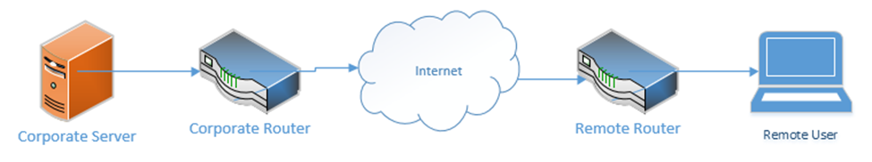
A VPN is a Virtual Private Network. It allows a remote user (working from home, a hotel, a hotspot, etc.) to connect to a corporate network through a tunnel. Essentially, the traffic from the user’s computer is packaged and sent through a tunnel to the corporate network. If the user attempts to access a website while connected to the VPN, that request is first sent to the corporate network, which forwards the request to the website. The corporate network also takes the traffic that it received from the website and sends it back to the user through the VPN. Therefore, traffic received from the user appears to be coming from the corporate network, regardless of the user’s location.
A VPN “tricks” the user’s computer into thinking that it is on the corporate network so that the user can access resources such as internal applications, shared drives, and printers.
A VPN concentrator is a device that collects and manages VPN connections from multiple users and passes their traffic to the LAN. It could be hardware-based or software-based. The VPN concentrator functionality can be incorporated into another network device such as a router.
VPN functionality is incorporated into devices such as
- Cisco Routers
- Cisco ASAs
- Fortigates
- Sonicwalls
- Cisco Meraki Routers
Remote users can use software to establish VPNs (such as Windows VPN or Cisco AnyConnect) or can install hardware-based VPN appliances such as a Meraki Z3.
Features of the VPN concentrator include
- Remote Access vs. Site-to-Site. A Remote Access VPN allows users to connect back to a corporate network, typically through their computer. A Site-to-Site VPN allows two offices to connect to each other and pretend like they are part of the same physical network. A Site-to-Site VPN typically applies to the site’s router and not to individual devices on the network.
- The performance on a VPN is affected by the quality of the user’s internet connection, by the quality of the corporate network’s internet connection, by the number of active users, and by the type of resources being accessed.
- When there are multiple sites that need to be connected, a site-to-site VPN should be replaced by a WAN
- The performance on a VPN is affected by the quality of the user’s internet connection, by the quality of the corporate network’s internet connection, by the number of active users, and by the type of resources being accessed.
- IPSec. IPSec is a set of protocols that allow hosts to exchange packets securely. IPSec has several modes of operation, including
- Tunnel Mode. The Tunnel Mode encrypts the source, destination, and contents of every packet. Essentially, it establishes a secure tunnel between two network devices where data can travel securely. The devices that are establishing the tunnel are not necessarily the devices that are creating the traffic. For example, a router could be sending traffic on behalf of a server inside the network. An outsider will not be able to examine the source, destination, or contents of any traffic.
- Transport Mode. The Transport Mode only encrypts the contents of the packet. It does not encrypt the source or destination. An outsider will be able to examine the source and destination. Transport Mode is established by the two network devices who are communicating, and not by the routers on the edges of the network.
- SA. An SA, or Security Association is an algorithm and key that are used to encrypt traffic in an IPSec tunnel. Each direction of communication requires a separate SA. Therefore, most IPSec tunnels will require two SAs.
- There are four methods of connecting a tunnel. Consider that two computers (each inside a separate network and behind a router) would like to communicate securely across the internet. How can an IPSec tunnel be established?
- Machine-to-Machine. Two computers (or smartphones) establish a tunnel and communicate. This is not practical because each computer will expend a substantial amount of computing power encrypting and decrypting the IPSec traffic.
- Router-to-Router. It is assumed that the connection between the computer and the router (on the internal network) is secure. The routers establish an IPSec tunnel. The computers no longer encrypt traffic between themselves and the routers. The routers encrypt all traffic between themselves.
- Machine-to-Machine and Router-to-Router. This combines the previous two scenarios. Each machine establishes an IPSec tunnel with the router on its network, and the routers establish an IPSec tunnel between themselves.
- Remote User. A remote user connects to a router through an IPSec tunnel, and then establishes a secondary IPSec tunnel to connect to a device deeper in the network.
- Machine-to-Machine. Two computers (or smartphones) establish a tunnel and communicate. This is not practical because each computer will expend a substantial amount of computing power encrypting and decrypting the IPSec traffic.
- Tunnel Mode. The Tunnel Mode encrypts the source, destination, and contents of every packet. Essentially, it establishes a secure tunnel between two network devices where data can travel securely. The devices that are establishing the tunnel are not necessarily the devices that are creating the traffic. For example, a router could be sending traffic on behalf of a server inside the network. An outsider will not be able to examine the source, destination, or contents of any traffic.
- Tunnel Mode Encryption. The tunnel mode is the method for encrypting the traffic. Consider that two routers have created an IPSec tunnel and that behind each router is a computer that wants to communicate. What is the order of operations?
- The computer generates some data and places it in a packet.
- The computer puts the address of the remote computer in the header of the packet (or the address of the network that it is sending it to, when the network employs NAT – more on this later).
- The computer sends the packet to the router (through the switch)
- The router encrypts this packet, including the headers
- The router encapsulates this packet inside a larger packet and adds the recipient’s router address to the header
- The router sends the packet to the destination router
- The destination router removes the outer header, decrypts the packet, and forwards it to the computer inside its network
- Neither computer is aware of the existence of the IPSec tunnel
- Tunnel encryption works through the following security protocols
- AH. Authentication Header. When AH is used, the original IP header (created by the computer that generated the data) is visible to outsiders, but the contents are protected. AH protects the integrity of the data. That is, the recipient can be sure that the sender listed on the packet is in fact the true sender.
- ESP. Encapsulating Security Payload. ESP encrypts the contents of the data, but it does not guarantee integrity.
- It is recommended to use both AH and ESP, thereby providing privacy and integrity.
- AH. Authentication Header. When AH is used, the original IP header (created by the computer that generated the data) is visible to outsiders, but the contents are protected. AH protects the integrity of the data. That is, the recipient can be sure that the sender listed on the packet is in fact the true sender.
- IPSec algorithms
- IPSec is a framework for exchanging data, but the contents of the framework vary from vendor to vendor and network to network. Just like there can be many different models of vehicles on a road, all following the same traffic rules, there can be many different types of algorithms to exchange data within a tunnel.
- Many different encryption algorithms can be used. This flexibility allows an algorithm to be replaced when it is discovered to be weak.
- Methods include
- Diffie-Hellman key exchange with public key signing
- MD5 and SHA-1 hashing algorithms to ensure data integrity
- Diffie-Hellman key exchange with public key signing
- IPSec is a framework for exchanging data, but the contents of the framework vary from vendor to vendor and network to network. Just like there can be many different models of vehicles on a road, all following the same traffic rules, there can be many different types of algorithms to exchange data within a tunnel.
- IPv4 vs IPv6. IPSec is integrated into all IPv6 packets by default, but not IPv4 packets. When IPv4 was designed, security was not a primary consideration. As the internet grew, the design of IPv6 required security to be integrated into all communications. A device can use IPv6 and not activate the IPSec feature however.
- The computer generates some data and places it in a packet.
- Split Tunnel vs. Full Tunnel
- In a Full Tunnel VPN, all traffic is routed through the VPN, but in a Split Tunnel VPN, only specific traffic is routed through the VPN.
- The advantage of a split tunnel is that it reduces bottlenecks. Consider a corporate user working from home. The user needs to access network resources such as a shared drive and corporate finance applications. This traffic must go over the VPN. The user is also watching YouTube videos in the background. There is no reason to route YouTube videos over the corporate network (requiring encryption on both sides). YouTube traffic can travel over the user’s home internet connection.
- In a Full Tunnel VPN, all traffic is routed through the VPN, but in a Split Tunnel VPN, only specific traffic is routed through the VPN.
- TLS. In addition to providing internet security, Transport Layer Security is an alternative to IPSec VPN. A TLS VPN is useful when the network uses NAT.
- Always-On VPN. An Always-On VPN is just like it sounds. It is a VPN that is always on. Typically, an Always-On VPN is part of a hardware appliance, but it could also be software-based. When the VPN detects an active internet connection, it automatically attempts to re-establish the VPN.
For security purposes, an Always-On VPN can block traffic from travelling over the internet when the VPN is not running. This would prevent a user from inadvertently disclosing his true location to websites that shouldn’t know it.
AAA/RADIUS Server
AAA or Authentication, Authorization and Accounting is a concept of verifying the identity of a user, providing him with access to specific resources, and keeping track of each access attempt. RADIUS stands for Remote Authentication Dial-In User Service and is a form of AAA.
When a user attempts to access a device, that device asks the AAA or RADIUS server for permission to allow the user. The server determines whether to allow or deny access to the user and responds to the device. The server also determines how much access the user is entitled to.
An AAA/RADIUS server can be installed locally or remotely. We will look at RADIUS in more detail later.
UTM Appliance
UTM stands for Unified Threat Management. It is the term given to most modern enterprise firewalls, which can include antivirus, antimalware, SPAM filtering, and intrusion detection tools all in one box. A threat from a single malicious actor can enter the organization through multiple routes. For example, a hacker could enter an organization’s network through an unsecured firewall, log in to a server that has weak credentials, and install a piece of malware that allows him to copy the corporation’s sensitive data.
UTM devices can detect patterns in network traffic and user activity. They can send this data to the cloud where it can be further analysed to determine whether it is a threat.
A UTM must be connected to the internet to be effective. Like any other threat management application, a UTM must be properly configured.
VoIP PBX
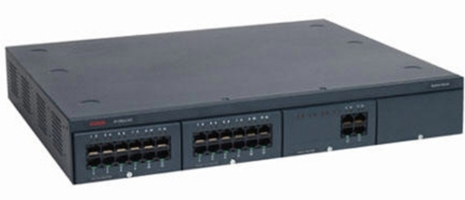
A PBX or Private Branch Exchange is a device that manages a phone system. There are several models
- Cisco Unified Communications Manager
- Avaya IP Office 500 V2
The PBX does the following
- Provides DHCP to each phone
- Configures each phone
- Routes phone calls between phones on the same network
- Routes phone calls between phones and the outside world (through connections with analog phone lines or a SIP trunk)
- Manages voice mail for the system
Typically, each time a phone powers on, it contacts the PBX and downloads its configuration. The PBX can identify each phone by its MAC address. The PBX can be directly connected to each phone or connected to the same network as each phone.
Some VoIP phones operate in the cloud, and do not require a PBX. Cloud-based VoIP phones do not function with analog phone lines.
An example of a PBX is below.
VoIP Endpoint
A VoIP Endpoint is a device that connects a user to a VoIP network. In other words, it’s a fancy name for a phone. Other devices that could be endpoints are ATAs (allows an analog device such as a fax machine or alarm system to connect to a VoIP system) and conference room phones.
A VoIP Endpoint connects directly to a switch. A VoIP endpoint may operate on a separate physical network from the rest of the LAN or may operate on a separate VLAN.
Some VoIP phones support IP Passthrough. Passthrough is useful when the building does not have enough ethernet wiring to support the installation of phones and computers. For example, a desk may have only one ethernet cable, but a user must connect both a phone and a computer. The solution?
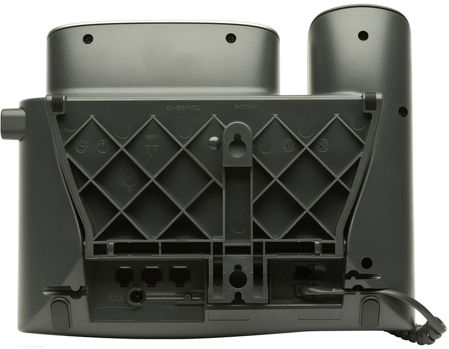
The phone connects to the network and to the computer. The phone acts like a little switch. It passes the ethernet connection through to the computer. Notice on the back of this Cisco phone, there are two ethernet ports (the port on the far left is used to connect an expansion module). The port in the middle connects to the ethernet. The port on the right connects to a computer. The traffic for the phone can be on a separate subnet (VLAN) from the traffic for the computer.
Printer
A printer can connect to the network (as opposed to via USB or serial). A network printer can accept print jobs from local and remote users. If equipped, a user can also scan documents from the printer direct to a network folder or to e-mail.
Physical Access Control Devices
An access control device is part of an access control system. An access control system is used to track and restrict access to different buildings or rooms. It typically has four parts
- A card reader and/or biometric reader – this device is installed next to each doorway and scans user proximity cards or biometrics
- A door lock – an electronic door lock that allows the door to be unlocked automatically. This might be known as a door strike.
- A controller – the controller connects to both the card reader and the electronic door lock. When a user scans a card at a card reader, the card reader reports the user’s information to the controller. The controller checks the time and decides whether the user is permitted to access that door. If the user is permitted, then the card reader sends a signal to the lock to unlock the door.
- The wiring between the controller and the card reader.
The access control system can be wired as follows (depending on the make and model of the system)
- The controller is connected directly to the network and power. The controller powers the card reader and door lock. The controller connects to each card reader and door lock via a proprietary cable. The door lock and card reader communicate with the controller via the proprietary cable. The controller may have a software program or web-based interface where it can be programmed.
- The controller is connected directly to the network. Each card reader and door lock are also connected to the network and receive power via PoE. The card reader and door lock use the network to communicate with the controller. They might be on a separate VLAN or on a separate physical network.

Cameras
IP Surveillance cameras can be connected to the network. There are several components
- The camera – several makes, and models of cameras are available with different types of lenses, zoom, quality, and weather ratings
- The NVR (Network Video Recorder) – video from the camera is recorded onto the NVR. The NVR is available in various storage capacities. Some NVRs have a built in PoE switch which can power the cameras and provide them with IP addresses.
- The network – the physical network infrastructure consists of ethernet cables (cat5e or cat6 between the NVR and the camera. It may also consist of the underlying network switches and routers that connect the cameras with the NVR.
There are several scenarios
- We can connect an analog camera to a coaxial cable. The analog camera has no way to communicate with the network. A network encoder is a device that converts the analog signal from the coaxial cable into a digital signal. The digital signal can be sent to an NVR where it can be recorded.
- We can connect an IP camera directly to the NVR. Many NVRs have switches that can power the cameras and provide IP addresses.
- If our NVR does not have capacity to directly connect all of the cameras, or if the distance between the NVR and the camera is too far, we can connect the NVR and the cameras to our network switch (or to multiple network switches if our network is large).
If we have multiple cameras, they can all connect to the same switch. The surveillance camera system can have a separate VLAN from the remainder of the network.
In most scenarios, the NVR has two VLANs: one VLAN for the camera and one VLAN for managing the NVR and viewing the recorded or live video. - We might use a combination of the above scenarios. If we have a combination of analog and IP cameras, some might connect via ethernet and some might connect via converters.
Heating, Ventilation, and Air Conditioning (HVAC) Sensors
Traditionally, a building’s ventilation system consisted of the following
- A rooftop unit – this brings cool air from the outside and warms it as necessary
- Exhaust fans – exhaust fans export stale air from the building
- Ducts – ducts transport air throughout the building
- Fans – fans blow air through the ducts
- Temperature sensors – sensors measure the temperature throughout the building.
- Controller – the controller makes the system work. Each temperature sensor reports the local temperature back to the controller. If an area is too cold, the controller instructs a nearby fan to turn on and blow more air into the area. The controller also instructs the rooftop unit to heat more air up for the building.
A temperature sensor is typically connected to the controller via a single-pair thermostat wire. Newer, IP based systems use Ethernet. The controller connects to the network via an ethernet cable, and so do the sensors. The controller and the sensors can connect on a separate physical network or can connect to the building’s main network and use a separate VLAN. The controller might also have a web interface that can allow a building operator to remotely program it or view its status.
Internet of Things (IoT)
The Internet of Things is a new concept that relates to devices that connect and communicate independently. It refers to devices other than computers. Many of these devices use Wi-Fi to connect to the internet. They do so to provide users with updates and to download firmware updates.
The internet has created a catch-22 scenario in that
- Devices have become complicated enough to connect to the internet
- The software required to run the devices has become more complicated
- Complicated software frequently experiences additional security holes
- To patch the additional security holes, the devices must stay connected to the internet to download software updates
Some of the devices include
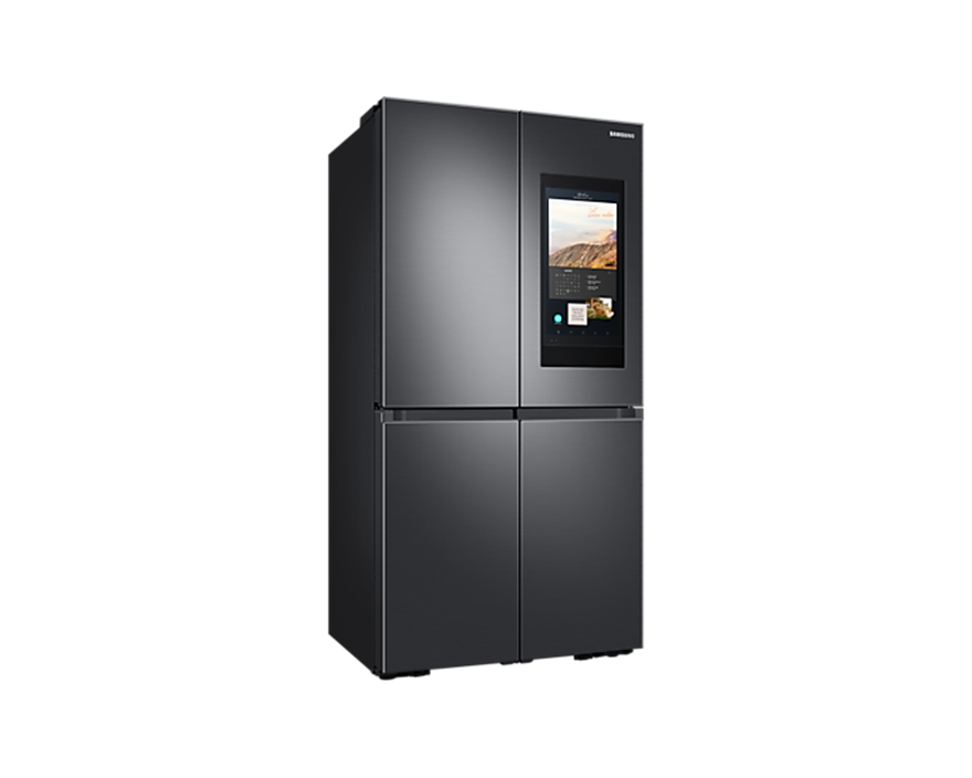
- Refrigerator – an example of a smart refrigerator is the Samsung with the Family Hub. The Hub is a touch screen, built in to the refrigerator, that allows family members to share updates and calendars in a way that mimics the use of fridge magnets. The Hub also allows users to view recipes, watch television, and play music while cooking.
- Smart Speakers – Smart Speakers refers to a general set of devices with artificial intelligence. A smart speaker can include a device such as a Sonos, which is a battery-powered Wi-Fi connected speaker. When you link the speaker with your cellular phone, you can stream music to it.
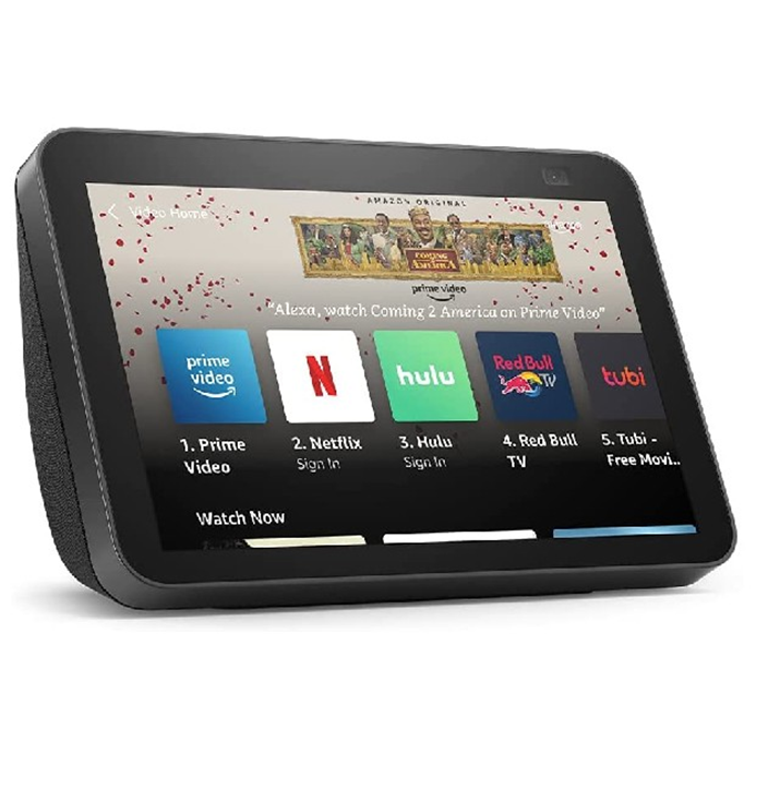
More advanced speakers have “tablet” screens. They include Google Assistant, Amazon Alexa, and the Amazon Echo. These smart speakers can display content that you request, including news, videos, and music. They can also connect with other devices such as thermostats and doorbells.
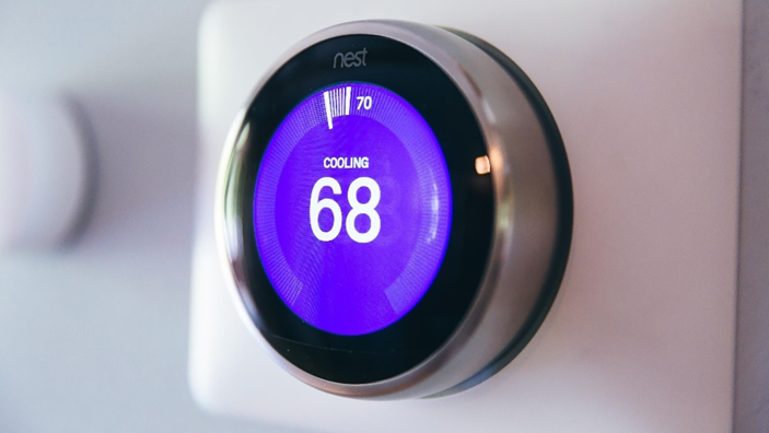
- Smart Thermostats – A smart thermostat is a device that uses artificial intelligence to regulate the temperature of a location.
A traditional thermostat has two functions. A user sets the desired temperature on the device. The thermostat continually monitors the temperature of the location. It also directly connects to the heat source. If the temperature of the location is too high, the thermostat does nothing. If the temperature of the location drops below the set temperature, the thermostat instructs the heat source to power on. When the temperature reaches the set point, the thermostat instructs the heat source to power off.
A smart thermostat does the same thing as a traditional thermostat. The only difference is that it monitors the environment and user habits to independently adjust the set temperature. For example, the smart thermostat might lower the temperature when nobody is home to reduce the cost of heating the building. The thermostat might set the temperature based on the user’s physical location.
- Smart Doorbells – A smart doorbell is a device that replaces a traditional doorbell. A traditional doorbell has two components: a button and a speaker. When a person presses the button, the speaker inside the house generates a sound.
A smart doorbell replaces the button. It usually takes power from the doorbell wiring.
A smart doorbell may have the following features- Camera that a user can view on their phone or computer
- Two-way communication (speaker and microphone) to communicate with visitors
- Motion sensor
- Camera that a user can view on their phone or computer
The most popular smart doorbell is the Ring doorbell. Most doorbells have limited power, so they only record video when they sense motion.
Industrial Control Systems / Supervisory Control and Data Acquisition (SCADA)
SCADA stands for Supervisory Control and Data Acquisition while ICS stands for Industrial Control System. These systems are found at power plants, factories, utilities, and other critical forms of infrastructure.
An ICS is designed to operate reliably 24 hours per day, 7 days per week for many years, without interruption. Multiple ICSs can be combined to operate redundantly. An ICS may consist of many PLCs – Programmable Logic Controllers. A PLC is a special type of industrial computer that collects input from sensors, uses an algorithm to make decisions, and send an output to different control units.
For example, a PLC could be connected to a water pump that is filling a tank with water, and a sensor that is monitoring the tank’s water level. The PLC continuously monitors the tank’s water level. When the tank is empty, the PLC directs the pump to pump water, and when the tank is full, the PLC directs the tank to turn off.
Multiple ICSs can be connected to a SCADA system. The SCADA system collects data regarding a process. For example, the SCADA system can collect data from an oil refinery to determine the quantity of crude oil being turned into gasoline and can collect data from thousands of steps along that process. This data is typically sent to a control room where operators can analyse the data and detect discrepancies.
The different components of the SCADA system can be housed close together or may be far apart. SCADA system components may communicate over a standard IP network via copper or fiber links.
Ideally, a SCADA system should be air gapped and isolated from any commercial network. This is not always possible because a SCADA system may control facilities that are physically separated by hundreds of kilometers. For example
- SCADA system that controls the traffic lights in a major metropolitan city
- SCADA system that controls the power grid in the North Western United States
- SCADA system that monitors multiple oil refineries in a state
The SCADA system’s communications should be
- Securely encrypted
- Air gapped and isolated from any commercial network, where possible
- On a dedicated WAN connection where air gapping is not possible due to distances
Yet there are many SCADA systems in use today that are accessible remotely (due to the negligence of the installer or manufacturer), some without a password. It is possible to locate these systems simply by running a port scan.
SCADA should be physically isolated from the commercial network. For example, a nuclear plant should not allow any part of the SCADA network to interact with the plant’s commercial network.
SCADA systems should not communicate wirelessly unless necessary, and where extreme precautions have been taken to ensure that all data is encrypted.
Many components inside the SCADA system may communicate without encryption. An air-gapped SCADA network can be easily disrupted if a malicious user has physical access to any SCADA network equipment or wiring. A malicious individual could splice the wiring between two SCADA system components and
- Disrupt the communication. For example, a conveyor belt is being used to load a truck with fertilizer. A hacker could cut the wire between the PLC and the conveyor belt motor, in which case no trucks could be filled. This behavior would disrupt operations.
- Spy on the communication. For example, a hacker could spy on the content of the communication to determine the quantity of oil being refined; the hacker could use this data to predict oil prices on the open market and place trades.
- Substitute inaccurate data inside the communication. For example, SCADA systems are used to control traffic lights in many major cities. These systems connect over unencrypted wireless systems or analog telephone lines. A hacker could disrupt the traffic patterns and bring intersections to a halt.
According to NIST Guidelines for SCADA Systems (NIST Special Publication 800-82), good SCADA security should
- Restrict logical access to an ICS network (using firewalls, multiple network layers, a DMZ, and unidirectional gateways)
- Restrict physical access to an ICS network
- Protect ICS from exploitation (install and test patches when available, disable unused ports and services, restrict user privileges to only those that need it, monitor and audit use of the system, check for file integrity)
- Restrict modification of data
- Detect security incidents (detect security events before they become incidents, detect failed ICS components and overloaded resources)
- Maintain functionality during adverse conditions (ensure that there is no single point of failure, that critical components have redundant counterparts, that the failure of a specific component does not create additional traffic or cascading effects, that if the system is to operate in a degraded state it does so gracefully)
- Restore the system after an incident (organization should have an incident response plan which includes key roles for all individuals involved, a well documented system, back up of all configuration, readily available replacement parts, and support from manufacturers and vendors)
An example of a virus that affects SCADA systems is Stuxnet. The Stuxnet virus
- Infected computers and hid its presence through a root kit
- Infected the firmware on USB drives inserted on those computers (the firmware on a USB drive does not contain any user storage and is typically inaccessible by any form of operating system or antivirus program)
- Searched for and infected any computer running the Siemens Step7 software application (which controls PLCs)
- Once locating a PLC, modified the code on the PLC so that it would cause damage, but returned normal values to the computer (so that the operator was unaware as to the harm that was being caused)