
2.3 Given a scenario, configure and deploy common Ethernet switching features
- Data Virtual Local Area Network (VLAN)
- Voice VLAN
- Port Configurations
- Port Tagging/802.1Q
- Port Aggregation
- Link Aggregation Control Protocol (LACP)
- Duplex
- Speed
- Flow Control
- Port Mirroring
- Port Security
- Jumbo Frames
- Auto-Medium-Dependent Interface Crossover (MDI-X)
- Media Access Control (MAC) Address Tables
- Power over Ethernet (PoE) / Power over Ethernet Plus (PoE+)
- Spanning Tree Protocol
- Carrier-Sense Multiple Access with Collision Detection (CSMA/CD)
- Address Resolution Protocol (ARP)
- Neighbor Discovery Protocol
I mentioned VLANs and switches earlier, but now let’s take a closer look. We already said that if we have a single physical network with an IP address range, we can break it up into multiple subnets. And we can assign different types of devices to different subnets (for example, computers, phones, security cameras, etc.).
When we have different devices with different subnets connected to the same physical switch, we need to make sure that their traffic stays separate.
We could create a VLAN or Virtual Local Area Network. We could assign each switch port to a single VLAN. Any device connected to that port belongs to that particular port’s VLAN.
A host such as a phone, computer, or switch will belong to a single VLAN.
Simple switches do not support VLANs. These are commonly known as unmanaged switches. On an unmanaged switch, all the ports belong to VLAN 1 and there is no option to add additional VLANs.
What if we have a large network with multiple switches? Let’s say we have one core switch and ten edge switches. And let’s say we have ten VLANs. If I want a device on VLAN 1 switch 1 to be able to talk to a device on VLAN 1 switch 2, then I need to choose a port on the core switch and a port on switch 1, set each of them to VLAN 1, and connect them with a patch cable. I could do this for the other nine VLANs and the other nine switches, but then I’d run out of switch ports. My core switch might only have 48 ports. Clearly this is not a good solution.
How can we transport traffic from multiple VLANs between the same set of switch ports? We can use a trunk port. We choose a port on the core switch, and a port on switch one, and connect them with a patch cable. Then we configure them as trunk ports. We tell the switch which VLANs are permitted to transport their traffic through that trunk port.
A Trunk port carries traffic for multiple VLANs. Each frame is tagged with its VLAN. Ports that are not trunk ports are known as Access ports. An Access port belongs to a single VLAN. The switch assumes that traffic through that port belongs to the VLAN assigned to the port. The standard for VLANs is called 802.1Q.
This brings us to our next point: Tagging and Untagging ports. An access port is known as an untagging port or untagged port, because it strips the VLAN tags off any traffic it receives and because traffic passes through the port untagged. A trunk port is known as a tagging port or a tagged port, because it adds VLAN tags to any traffic it receives, and because traffic passes through the port tagged.
Now we have three scenarios for traffic flow within the switches
- Traffic moving between two devices on the same VLAN and on the same switch. This traffic moves from one access port on the switch to another access port on the same switch.
- The switch receives the frame
- The switch realizes that the destination device is directly connected to the switch
- The switch realizes that the source port and the destination port are assigned to the same VLAN
- The switch forwards the traffic out of the destination port
- The switch receives the frame
- Traffic moving between two devices on the same VLAN but connected to different switches.
- The switch receives the frame
- The switch realizes that the destination device is connected to another switch through a trunk port
- The switch tags the frame with the VLAN ID of the port it was received on
- The switch forwards the frame through its trunk port to the appropriate switch
- The receiving switch receives the tagged frame
- The receiving switch realizes that the destination is directly connected to it
- The receiving switch removes the VLAN ID from the frame and sends the frame to the correct destination
- The switch receives the frame
- Traffic moving between two devices on a different VLAN
- The switch will forward the traffic to the router and the router will decide whether to forward the traffic back to the switch
- If the switch is a Layer 3 switch, it may apply its own rules to forward the traffic
- The switch will forward the traffic to the router and the router will decide whether to forward the traffic back to the switch
It is important that we configure the same VLANs on every switch. If VLAN one on switch one is VLAN two on switch two, it takes little to imagine what kind of problems that would cause.
Every port can be assigned to one VLAN only. There is one exception. Access ports on a Cisco switch can be configured with two VLANs. Why? In a large organization using VoIP, the VoIP phones are connected on one VLAN and the computers are connected on another VLAN.
This is known as IP Passthrough because the phone passes the computer’s traffic through to the switch. The main advantage is that the organization only requires one cable per user. The Cisco switch knows how to separate VoIP and user traffic.
Each switch port can have several attributes that can be configured
- Port Tagging – whether the port is an access port or a trunk port
- Port Aggregation – whether multiple ports can work together to transmit data
- VLAN – the VLAN assigned to the particular port, or the VLANs allowed to be transported over that port if it is a trunk
- Duplex – whether the port operates at full duplex or at half duplex. That is, whether it talks and listens at the same time (full duplex), or whether it waits for the other device to stop talking before it starts.
- Speed – we can manually set the speed of the port. Available options depend on the switch, but the most common are 100 Mbps and 1 Gbps. Slower switches had the ability to choose either 10 Mbps or 100 Mbps. Newer, faster switches offer 2.5 Gbps, 5 Gbps, 10 Gbps, and 40 Gbps. These faster speeds might require an SFP.
If we don’t manually configure a duplex and/or speed, the switch and the other device connected to it will automatically agree on a speed and duplex through a process called autonegotiation.
If we manually set a speed and duplex on only the switch or on the other device, the device that is not manually set will try to figure out the correct speed and duplex setting and attempt to communicate via the correct setting. - Flow Control – flow control allows a switch to tell the sender to slow down the amount of data it is sending. The purpose is to allow the switch to catch up when it is overwhelmed with the amount of data being received; the alternative being that the switch will begin dropping the traffic, resulting in data loss.
- Port Mirroring – Port Mirroring is a feature where the switch passes the same traffic on two different ports. For example, if we wanted to monitor Port #4, we could tell the switch to mirror Port #4 onto Port #8. Now the switch will duplicate traffic leaving Port #4 onto Port #8. We can monitor Port #4’s traffic by connecting a monitoring device onto Port #8.
Port Mirroring is known as Switched Port Analyzer (SPAN) or Remote Switched Port Analyzer (RSPAN) on Cisco devices. We can monitor incoming and outgoing traffic. Why would we want to monitor traffic? We could detect intrusions or ensure that the network is performing as expected. - Port Security – Port Security is a method for controlling the devices that are permitted to talk to the switch. There are a number of settings and we will discuss port security in greater detail.
- Jumbo Frames – Jumbo Frames is a setting that permits or denies a port the ability to send or receive a packet larger than 1500 bytes
- Auto-Medium-Dependent Interface Crossover (MDI-X) – in the early days of ethernet, when we connected two switches together, we used a crossover cable (the pins are swapped). When we connected a router or other user device to a switch, we used a straight through cable.
If we enable the MDI-X feature, a switch port will automatically determine the type of cable that is connected and switch the pins that it uses to send and receive. Thus, users don’t have to worry about whether they are using a straight through or crossover cable. MDI-X is enabled by default, but only applies to speeds of 10 or 100 Mbps. Faster speeds use all four pairs and do not have dedicated transmit or receive pairs. - PoE – we can determine whether the port will provide power over ethernet (to power devices such as cameras, wireless access points, and phones)
Now we know that the switch receives a frame and tags it or untags it depending on the VLAN, etc. But how does the switch know what all of the devices connected to it are and which ports they are actually plugged in to?
Introducing the MAC Address Tables. A switch remembers the MAC address of every device that is connected to it. Well, the switch has a huge table called the MAC Address Table. When the switch first powers on, this table is completely blank. Each time the switch receives a frame, it checks the source MAC address on the frame.
Let’s say the switch received a frame on Port 27, from a device with the MAC address AA:AA:AA:AA:AA:AA. It now knows that a device with the MAC address AA:AA:AA:AA:AA:AA is connected to Port 27 (it doesn’t matter if it is directly connected or connected through another switch). The switch updates the table to reflect this information. Each time the switch receives a frame, it updates the table.
Second, when the switch is ready to forward that frame, it checks the table. Every frame has a destination. If the switch later receives a frame addressed to a device with MAC address AA:AA:AA:AA:AA:AA, it knows from the table that it should forward that frame out of Port 27. Remember that since a switch can be connected to other switches, and since each of those switches can be connected to dozens of devices, a single port on a core switch could see frames coming from dozens or hundreds of MAC addresses.
If the switch receives a frame addressed to a MAC address that is not in the table, then it sends that frame out all its ports, except for the one on which it received the frame. This is known as flooding. If VLANs are configured, then the switch only sends the frame out of the ports that match the VLAN on which it was received. But, but, but, then a whole bunch of devices will receive frames that aren’t addressed to themselves? Yes, but that isn’t a big deal. Legitimate network devices ignore frames that aren’t addressed to themselves.
The entries in the table only last about five minutes. If the switch doesn’t see traffic from a specific MAC address after five minutes, it deletes the entry in the table. The default time can be adjusted by an administrator.
The MAC address is the core of all switch logic.
How does a device know what MAC address to send its frame to anyways? That’s where ARP or Address Resolution Protocol comes in.
Let’s say my computer has a MAC address of AA:AA:AA:AA:AA:AA and an IP address of 192.168.1.2, and my printer has a MAC address of BB:BB:BB:BB:BB:BB and an IP address of 192.168.1.3. My computer knows my printer’s IP address (an administrator may have programmed it), but it needs to find out its MAC address so that it can send it a document.
My computer sends out a message known as an ARP request message. It addresses the message to the generic MAC address FF:FF:FF:FF:FF:FF. All network devices by default can read messages addressed here. My computer’s message in effect says, “if your IP address is 192.168.1.3, then tell me your MAC address”. This message is flooded over the entire network, but only the printer responds (because only the printer has that IP address). The printer sends an ARP response message back to my computer, indicating that its MAC address is BB:BB:BB:BB:BB:BB, basically saying “hey, my IP address is 192.168.1.3 and my MAC address is BB:BB:BB:BB:BB:BB”.
My computer maintains a table called the ARP table. It adds the information learned from the ARP response to the table. The ARP table contains a list of device MAC addresses and their corresponding IP addresses. Next time my computer wants to talk to the printer, it doesn’t need to follow the ARP process. It just checks the table. In fact, every time a computer needs to send an ARP message, it checks the ARP table first. If it doesn’t find an entry in the ARP table, then it sends out an ARP request message.
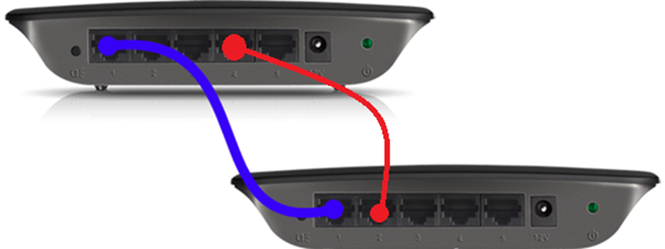
Now let’s say we did something stupid and connected two switches together with two cables. We now have a loop because the top switch sees all the MAC addresses from devices connected to the bottom switch (due to the blue cable), and all the devices connected to itself (due to the red cable). The same applies to the bottom switch.
Any frame that the switch attempts to transmit enters the loop and goes in circles. This results in unpredictable network activity. One common result is a broadcast storm. Remember that a broadcast is sent to everybody? Well, if the top switch receives a broadcast packet, it sends it to the bottom switch, which sends it back. The two switches send packets to each other until they crash.
How do we avoid this? We use a Spanning Tree Protocol (STP). The switches figure out how many connections they have amongst themselves. If two switches discover that they have multiple links, they turn all of them off except for one. STP works on small networks of just two switches and large networks that could have dozens or hundreds of switches. How does it work?
- First all the switches pick one switch to be the “root bridge”. The root bridge is switch with the smallest bridge ID. An administrator would manually configure a bridge ID on each switch. If there is a tie with the bridge ID, then the switches pick the switch with the lowest MAC address.
- Each of the remaining switches figures out how it is connected to the “root”. If a switch has multiple connections, it assigns a cost to each one. The greater the bandwidth, the lower the cost. For example, a 100 Mbit/s link costs “19”, while a 1 Gbit/s link costs “4”. The switch turns off the most expensive links. The switches communicate the cost through Bridge Protocol Data Units (BPDUs).
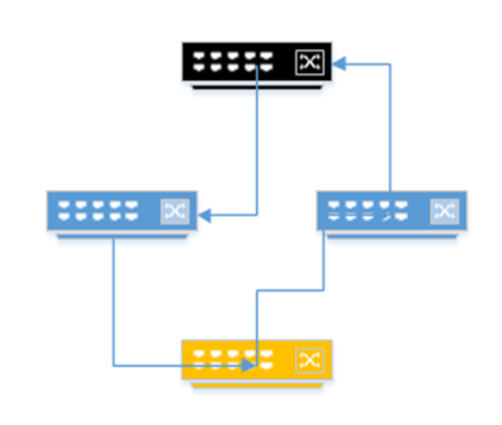
- Remember that the topology can become complicated. There may be several switches between an edge switch and the root switch. Thus, the pathway to the root may involve several links, each of which has its own “cost”. Consider the following diagram. If the black switch (on the top) is a core switch and the yellow switch (on the bottom) is an edge switch, the yellow switch has two links back to the root (one through the switch on the left and one through the switch on the right). It must calculate the cost of the entire pathway.
If the pathway through the switch on the left was least expensive, the bottom switch would turn off the link to the switch on the right. What if the bottom switch needed to send traffic to a device connected to a switch on the right? It would have to send it through the switch on the left, and the switch at the top.
- If multiple pathways have the same cost, then the switch chooses the pathway containing the neighboring switch with the lowest bridge ID.
- A port can have any of the following statuses:
- Blocking. The switch determined that this port will cause a loop. It does not send or receive any traffic on this port, except for BPDU data.
- Listening. The port does not transmit data, nor does it learn MAC addresses, but it is still watching for BPDU data that would make it switch to a blocking state.
- Learning. The port does not transmit data, but it still learns MAC addresses of devices that could be connected to it, and adds them to the MAC address table.
- Forwarding. A normally operating port. All data is transferred. The port is still watching for new BPDU data that would make it switch to a blocking state.
- Disabled. The port was manually turned off or turned off due to a security incident. We’ll talk about security incidents later. No data is transferred, not even BPDU data.
- Blocking. The switch determined that this port will cause a loop. It does not send or receive any traffic on this port, except for BPDU data.
- When the port first activates (when something is first connected to it) the port will first enter the listening state and then the learning state. It will remain in this state for about 15 seconds, although the value can be changed by an administrator. If it doesn’t find any adverse information from the BPDU data then it will switch to a forwarding state.
- The switches continually revaluate their connections and recalculate the cost of each link. Switches exchange Bridge Protocol Data Units every two seconds.
- The switches also continually test their data links. If a link fails, the switch activates a more expensive link. If a less expensive link starts working again, the switch returns to sending traffic over it. A switch tests its link by sending a “hello” message every two seconds. If the switch does not receive a reply after three “hello” messages (six seconds), it assumes that the link is defective and chooses a new link.
We might call this Rapid Spanning Tree Protocol (RSTP). RSTP is an improvement over the original STP and is proprietary to Cisco.
- In RSTP, there are three port states
- Discarding. The port does not send or receive any traffic.
- Learning. The port does not send any traffic, but it does learn MAC addresses of devices connected to it.
- Forwarding. The port is sending and receiving traffic normally.
- Discarding. The port does not send or receive any traffic.
What if I had a really big network and I decided that one cable between my switches wasn’t enough to handle all the traffic? What if I needed two or three cables? How can I make such a connection without creating a loop?
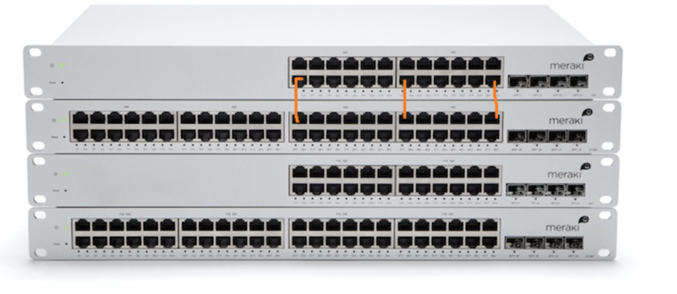
We could use Link Aggregation Control Protocol, or LACP. Link Aggregation is also known as Port Aggregation or Channel Bonding. Link Aggregation allows us to combine multiple physical ethernet links into a single logical link. LACP has automatic failover detection. We could choose between two and eight ports to use in the link.
The links must be assigned to the same logical switch and they must all have the same speed.
How does the switch decide which packet to send down which physical link? It uses a scheduling algorithm that looks at the source and destination IP addresses and MAC addresses. The goal of the algorithm is to randomize the use of each link so that the load is balanced.
Finally, let’s say we wanted to connect a VoIP phone, an access point, or a surveillance camera to the switch. These devices require power. But it’s a hassle to connect the device to an ethernet cable and to a power outlet. That’s where PoE (Power Over Ethernet) comes in. PoE lets a switch power a network device over the same ethernet cable that it communicates on.
PoE is governed by the 802.3af standard and delivers up to 15.40 W. PoE+ delivers up to 30W. Type 4 PoE delivers up to 100W. A switch capable of delivering PoE is called a PoE switch and is typically more expensive than a non-PoE switch. You must choose a switch that has enough overall capacity to power all the devices connected to it.
If you only had one or two devices that required PoE, you might connect a power injector instead. A power injector sits between the switch and the device requiring power. It takes data from the switch, adds power, and sends it to the device.
You can enable or disable PoE on a per-port basis. Devices that require PoE have a resistor inside their network card between two of the pins. When you connect a PoE-capable device to a switch, the switch will detect the high resistance and send it power. This prevents the switch from sending power to a device that doesn’t require it, which could potentially damage the device.
What if all the devices want to talk at the same time? What if one device wants to send a message to many devices at the same time? We can learn some concepts
- Broadcast Domain. A broadcast domain is a network segment. Your entire office (everything behind the router) is one broadcast domain, even if it has many switches.
If one device wants to talk to all the other devices, it sends a message known as a broadcast frame (or broadcast packet). The switch receives the broadcast frame and passes it on to all the devices connected to it that are in the same VLAN. These devices make up the broadcast domain. A router will ignore broadcast frames.
We can separate a local network into multiple broadcast domains by implementing VLANs.
Why do we have broadcast domains? For example, a computer joins the network and chooses an IP address. It sends a broadcast message to the network to verify that no other device shares its IP address. Or a printer joins the network and announces its presence so that computers can find it. - CSMA/CD. Carrier Sense Multiple Access with Collision Detection. What happens if two devices want to talk at the same time on the same cable? Each device transmits a frame at the same time and a collision takes place.
A collision is bad, but at least we know that it happened. Both devices stop talking immediately. Each device sends a “jam signal”; a message to the other devices that tells them to be quiet. Each device picks a random amount of time to wait and then resends its frame. Hopefully, the next time, the line is free.
The collision detection method depends on the type of ethernet wiring in use.
In modern networks, CSMA/CD is not required. Collisions only took place on the old form of ethernet wiring, where many devices were connected to the same cable. - CSMA/CA. Carrier Sense Multiple Access with Collision Avoidance.
A device “listens” to the channel it is attempting to transmit on. If another device is transmitting, we wait a random amount of time and then listen again. The device might ask for permission to send its data, or it might just wait until it knows the line is clear. If the line is clear, or if the device is told that it can transmit the data, then it sends the data. - Collision Domains. All the devices that are at risk of having a collision make up a collision domain. In the modern world, collisions are not possible; therefore, each collision domain consists of a single device. Consider a computer connected to a switch via an ethernet cable. Only the switch and the computer can communicate over that cable. It is not possible for another device to send data along that physical ethernet cable.
- Protocol Data Units. A Protocol Data Unit is the smallest unit of information that can be transmitted on a layer. Remember I said that a computer breaks the data into chunks before sending it? Each chunk has an address and some other metadata to help it get to its destination. Well, on Layer 2, the chunk is called a frame, and contains the MAC address of the sender/recipient. If that chunk (frame) makes it to the router, the router adds some more metadata (like an IP address) to it so that it can get to its destination. That frame becomes a packet.
A PDU is like a letter. If you write a letter and put it in an envelope, the mailman uses the address on the envelope to decide where it goes. If you wrote a letter to your neighbor, the mailman might take it there himself. This envelope is like a Layer 2 PDU.
If you wrote the letter to a friend in another city, it might go into a mailbag that is thrown onto a truck and driven there. The mailbag has its own address (that of the post office in the other city). When the mailbag gets to the destination, the envelope is taken out and delivered to the recipient. The mailbag is like a Layer 3 PDU. Notice that the metadata for the previous layer is still present.
If you wrote the letter to a friend in another country, that mailbag might go into a shipping container. The shipping container is addressed to the central post office of the receiving country. The container is like a Layer 4 PDU. The container is opened at its destination and the mailbag is removed. The letter is removed from the mailbag and taken to its final destination. Notice that the metadata for the previous two layers is still present. - MTU. The Maximum Transmission Unit is the largest size PDU that can be transmitted over a particular layer and protocol. Each layer and each protocol has different limitations.
Remember that each PDU has metadata, and the amount of metadata is not affected by the size of the actual data. It’s like a letter. The letter has a to address, a from address, and a stamp. It doesn’t matter how long the letter is. If we send a document in one envelope or if we break it up into twenty envelopes, we must include the same addresses (metadata) on each envelope.
If the MTU is small, then a large portion of the data being transmitted is metadata. Thus, it is more efficient to have the MTU as large as possible. Each network device has physical limitations; therefore, the size of the MTU can be affected by the types of devices in use. When two devices establish a connection, they may agree on an MTU size.- IPv4 – between 68 bytes and 64 kilobytes
- IPv6 – between 1280 bytes and 64 kilobytes
- Ethernet – up to 1500 bytes