5.2 Given a scenario, troubleshoot common cable connectivity issues and select the appropriate tools
- Specifications and Limitations
- Throughput
- Speed
- Distance
- Cable Considerations
- Shielded and Unshielded
- Plenum and Riser-Rated
- Cable Application
- Rollover Cable/Console Cable
- Crossover Cable
- Power Over Ethernet
- Common Issues
- Attenuation
- Interference
- Decibel (dB) Loss
- Incorrect Pinout
- Bad Ports
- Open/Short
- Light-Emitting Diode (LED) Status Indicators
- Incorrect Transreceivers
- Duplexing Issues
- Transmit and Receive (TX/RX) Reversed
- Dirty Optical Cables
- Common Tools
- Cable Crimper
- Punchdown Tool
- Tone Generator
- Loopback Adapter
- Optical Time-Domain Reflectometer (OTDR)
- Multimeter
- Cable Tester
- Wire Map
- Tap
- Fusion Splicers
- Spectrum Analyzers
- Snips/Cutters
- Cable Stripper
- Fiber Light Meter
Now that we have an idea of the problem-solving framework, let’s look at some physical cable issues.
When a network connection is not working, what can you check for?
- Throughput – how much bandwidth are you getting? If you aren’t getting enough bandwidth, then maybe the entire system is lagging because too many people are downloading too many things. Or maybe the ISP is not giving you as much bandwidth as you are paying for. You need to identify the bottleneck.
- Speed – how fast is the connection? 10 Mbps? 100 Mbps? 1 Gbps? If your equipment is rated for 1 Gbps on both sides (the device port and the switch port) but your speed is 100 Mbps, you must investigate. Are the devices configured for the wrong speed? Is there damage to some of the pairs in the ethernet cable that prevent the devices from using its full capacity? Is there interference on the cable that is causing errors?
- Distance – how long is the cable? Does it exceed the recommended distance of 100m for copper or the manufacturer’s recommended distance for fiber? If the cable is too long, errors will result in the transmission.
Some ideas about cable types
- Is the cable shielded or unshielded? If there are sources of interference near the cable, then a shielded cable is necessary to prevent errors.
- Is the cable plenum rated or riser rated? A plenum rated cable is the only type of cable that is suitable for installation in a plenum space. What is a plenum space? It is the space above the ceiling where there is ventilation. Local building codes dictate that plenum cable must be used in the plenum space. A riser rated cable can be installed between floors but not in a plenum space. The plenum rating won’t affect the quality of the data being transmitted.
Are we using the correct type of cable?
- Check the pin out of the cable to ensure that it is correct for the application. Most applications will accept a straight-thru cable or a crossover cable. Remember that modern switches will detect and use either a straight-thru or crossover cable, so mixing them won’t usually cause an issue (unless the feature is disabled). Having said that, it is a good practice to only use straight-thru cables.
- A console cable is used for connecting to a switch or router. You must make sure that the console cable has the correct pin out for the device. Although console cables look alike, different manufacturers use different pin outs for their devices.
- If the device uses Power Over Ethernet, is the device’s PoE type compatible with the switch’s PoE type? Is the switch capable of PoE? Does the switch have PoE enabled on the port that the device is connected to? You might connect a PoE injector to the device and see if it boots up.
Some areas of concern in physical cable transmission
- Attenuation. Attenuation means that we have a physical loss of the signal power. The loss may be low or high. A small loss is expected over copper or fiber optic cable, but a large loss may indicate damage to the cable. The amount of attenuation can be measured in dB, and might be known as Decibel Loss.
- Interference. Interference means that we have some electromagnetic noise on the cable. It is common when the cables are installed parallel to high voltage power lines but does not typically cause data loss on cat6 or cat6A cable.
- Incorrect Pinout. When an ethernet jack is miswired, data cannot be transmitted. A commercially manufactured patch cable won’t typically have an incorrect pinout, but an ethernet jack installed in the field might.
- Bad Port. A bad ethernet port on a switch or device will result in errors, dropped connections, or no connection at all. A bad port on high quality switches is rare.
- Open/Short. An open means that the circuit is not a complete loop. In other words, a wire in the circuit has been cut and now the electrical signal has nowhere to go.
If you plug in a light bulb, electricity flows from the wall outlet, to the light bulb and back into the wall outlet. If you cut the wire or remove the light bulb, the electricity has no pathway, and now you have an open.
A short is caused when a wire touches another wire. It means that the electrical signal is flowing back to the source without passing through the device that needs it.
If you plug in a light bulb but cut the wires coming out of the wall and twist them together, you now have a short. In a high-voltage system, a short will activate a circuit breaker.
A cable tester can tell us whether we have an open wire or a short wire in an ethernet cable. - Light-Emitting Diode (LED) Status Indicators. We can check the LED status on an ethernet port to determine what it is doing. Typically, there are two lights: one tells us if we have a link (that is the two devices see each other) and the other one tells us if we have activity (the two devices are talking). The color of the lights and the pattern at which they blink can tell us
- Whether there is activity
- What speed they are connected at
- Whether there is PoE
- Whether there is half duplex or full duplex
- Whether there is activity
The pattern and color vary from manufacturer to manufacturer. But in general, a green light indicates a faster connection than an orange light, which indicates a faster connection than a red light. No lights mean that there is no physical connection.
If you connect two devices (a computer and a switch for example) via an ethernet cable, and you don’t see any link lights, then you have a problem. What might be the cause?
- Test the cable end to end to make sure that it has continuity and that the pin out is correct
- The ethernet port on the switch and/or the computer might be disabled. Check the configuration.
- The switch or computer might not be powered on
- The switch port is bad
- The ethernet port on the computer is bad
If you only see link lights on one device, that usually means that one device can transmit and receive but the other one can’t. This is usually caused by damage to some pairs in the cable. If it is a fiber optic connection, then one of the fiber strands may be damaged.
- Incorrect Transreceivers. Remember that a transreceiver allows a cable to talk to a switch or router. If we use the wrong transreceiver (for example we use a multi mode transreceiver and a single mode fiber), then no communication can take place. We must make sure to use the correct transreceiver for the correct fiber. We must also make sure that the transreceiver we use is compatible with the switch or router that it is installed into.
- Duplexing Issues. A duplexing issue happens when we have two devices trying to talk at the same time on the same wire. The result is that the data is transmitted down the wire and collides in the middle. A connection with a duplex issue will appear to be connected properly but will perform poorly with lots of errors.
The cause is usually that the devices have mismatched duplex settings. For example, one device is set to full duplex and the other is set to half duplex or to autonegotiate. - Transmit and Receive (TX/RX) Reversed. Remember that a switch transmits data on one pair of copper wires and receives data on another pair. It is not possible to reverse the pairs unless we use a crossover cable. The likelihood that this will happen is low since most switches can detect whether a straight-thru or crossover cable has been used.
When we have a fiber optic connection, the switch transmits data on one strand and receives data on another strand. If the strands are reversed, then the switch will not see a connection, because both devices are trying to transmit data on the same strand.
- Dirty Optical Cables. Dirty Optical Cables are the most common cause of transmission errors over fiber. We can examine the end of the cable with a measuring tool to verify if it is clean. If it is dirty, we should clean it with the appropriate cleaning tool.
At the beginning of this book, I told you about some tools you should have. When you come to work with the right tools, the job becomes much easier. The right tools are often high quality.
Some of the tools that you should have are below.
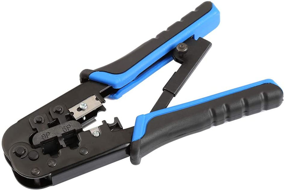
A crimper is used to fix a cat6 or cat5e male end onto a cable. This crimper below can crimp a cat3 male end (a 6-position plug) onto a cable as well. We would use this crimper to terminate a cable to a male end. It costs about $80.
Male ends are used in the field when we are directly connecting an ethernet cable to a device such as a surveillance camera or an access point. In general, at a server room, we should terminate the cable to a patch panel instead of a male end that is connected directly to a switch. Male ends are less reliable, and I do not recommend using them in the field either. I prefer to terminate my cables to female jacks. If I need to connect a camera or access point, I can plug it into the jack with a patch cable.
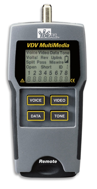
A cable tester tells us whether a cable has continuity. Remember that a cat6 cable contains eight wires. We connect the main part of the tester to one end of the cable being tested, and we connect the remote part to the other end. The tester tells us whether all eight wires are continuous (intact) from end to end.
This particular tester shows us the status of all eight wires at the same time. Some testers are only capable of testing one wire at a time. It also tells us if a wire is continuous but punched down on the wrong position of a jack. Finally, it can test coaxial cable and shielded cat6 cable. It costs about $150.
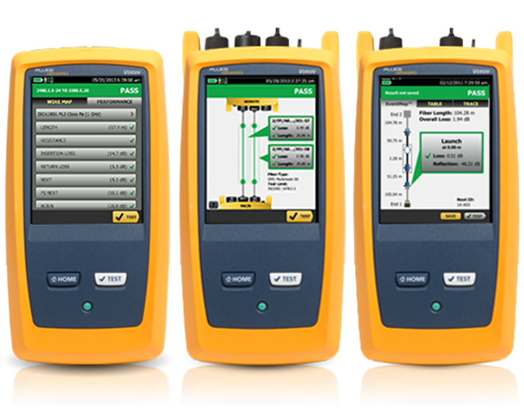
A more advanced device is a cable certifier. The cable certifier takes additional measurements in the cable to ensure not just that it has continuity but also that it is not subject to interference. It can save thousands of tests and generate a PDF report. Some customers require the use of a cable certifier after installation, which proves that the cabling was installed and terminated correctly.
Below is the Fluke Versiv cable certifier, which I use to certify copper and fiber optic cables. The certifier must be calibrated each year. It costs about $25,000 for a full package that includes modules for testing copper and fiber.
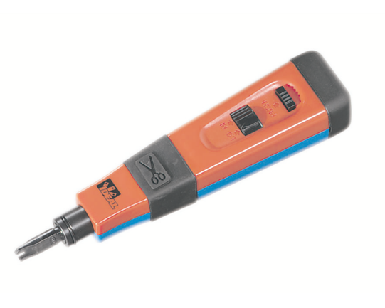
A punch down tool inserts wires into a jack and cuts off the excess. Punch down tools come with replaceable blades (such as BIX, Krone, 110, and 66). I recommend a punch down tool with a spring-loaded action, which is much easier to operate. It costs about $80.
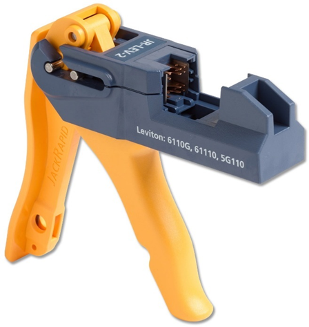
If you are terminating a large quantity of jacks, consider buying a tool that can punch down all eight wires at the same time. Below is the Fluke JackRapid Punch Down Tool. The tool has repeatable heads for different makes and models of jacks. You must buy the head that is compatible with the jacks that you are installing.
The tool can reduce termination time by up to 50%, reduce errors, and reduce the risk of hand strain. It costs about $150.
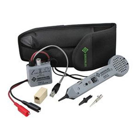
A tone generator (also known as a fox and hound) helps us find cables. Say we have a big mess of cables like in the photograph below. We found one end of the cable, and we’re trying to find the other end in this mess. We can use the tone generator.
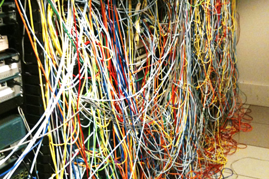
One end generates the tone. We connect it to the cable that we are trying to identify. The tone generator creates an audible tone that passes down the cable. We take the other end (called the wand) and wave it around in the mess of cables. It will create an audible alert when it is touching the correct cable.
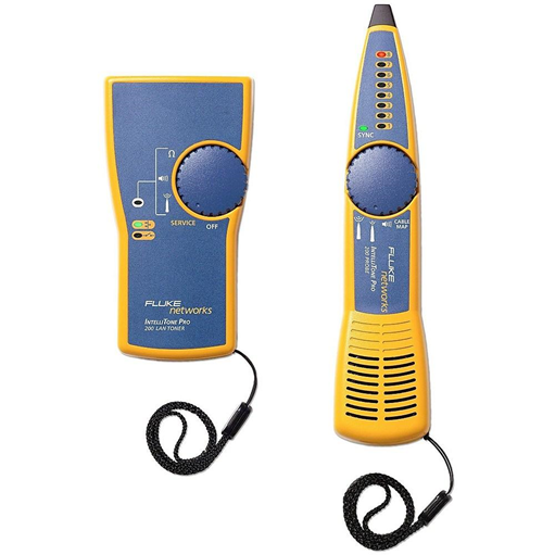
I recommend the Fluke IntelliTone Pro 200 because it works well even with long cables. When using other brands of toners, I find that the signal can bleed to other adjacent cables, causing inaccurate results. This toner also has a built-in cable tester, which makes it good for finding and terminating cables in a single trip.
Another good toner is made by Greenlee. The Fluke toner is better at finding cat5e/cat6/cat6A wiring, but the Greenlee is better at finding cat3 wiring. What is interesting is that the Fluke tone generator is compatible with the Greenlee wand, and vice versa. The Fluke toner costs about $300 and the Greenlee toner costs about $200.
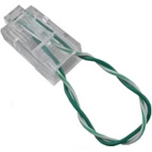
A loopback plug or loopback adapter is a device for testing a signal. If I have a DSL line or fiber optic cable coming from an ISP, how can I test it? I can’t take the other end of my cable tester to the ISP and plug it in there because the cable might be 10 km long!
But if the ISP has terminated their cable to a jack in my building, I connect a loopback plug like the one below. The ISP sends a signal down the wire, and the loopback plug sends the signal back to the ISP. If the signal arrives intact at the ISP, then the ISP knows that the line is working.
The loopback connector below is designed for a Smart Jack. We can use two standard fiber optic cables to create a fiber optic loop. You can buy a T1 loop for a few dollars, or you can make it yourself using a crimper, a male cat6 termination, and a small piece of cat6 cable.
An OTDR or Optical Time Domain Reflectometer is a device that measures defects in a fiber optic cable. Think about if we installed a 2km long fiber optic cable and we later notice that there is a problem. Maybe a mouse chewed through it. How do we know where the damage is? We use the OTDR. It shines a light down the cable. If the light encounters some damage, it bounces back. The OTDR can measure how long it took for the light to bounce back and how much of the light bounced back. Based on the time it took to bounce back, we can determine where the damage is.
The OTDR has advanced algorithms for processing the signal and can show us graphically how long the fiber is and where the damage is (even when the cable is damaged in multiple places).
The OTDR is only testing the glass strands inside the fiber. If OTDR won’t be able to detect physical damage to the cable jacket.
The cost of an OTDR varies between $2000 and $30,000. If you buy the Fluke Versiv, you can buy the OTDR module for an additional $10,000.
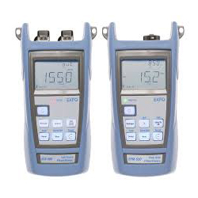
A light meter shines a light down the fiber optic cable and measures the brightness on the other end. If the light is bright enough, then we know that the cable is suitable for transmitting a signal. It doesn’t tell us whether the cable was terminated correctly or where it is damaged. It costs about $200.
A fiber optic strand that has some damage may still transmit enough light for the receiving device to process the signal.
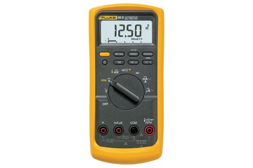
A multimeter allows us to measure the voltage, resistance, or wattage on a pair of wires. It may be suitable for diagnosing issues with DSL or phone lines, although I rarely use such a device. It can also tell us if a pair of wires has continuity. It costs between $50 and $500.
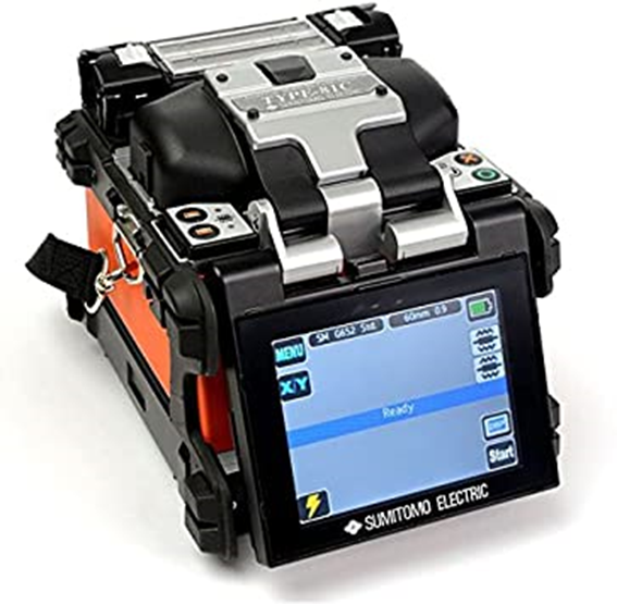
A fiber optic fusion splicer melts two fiber optic cables together. You can use this when terminating a fiber optic cable with a pigtail. You can also use it to repair a damaged fiber optic cable.
A fusion splicer can cost between $1000 and $25,000. I found that some of cheaper Chinese ones available on Amazon work just as well as the expensive Japanese ones.
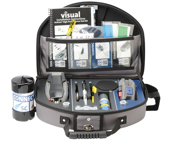
I used to use the Corning Unicam 2 fiber termination kit, which allowed me to mechanically terminate fiber optic cables. This kit cost $2500. For reasons discussed previously, we no longer mechanically terminate fiber optic cables.
Before terminating a fiber optic cable, you will need to strip the jacket off it. You must use a cable stripper that is designed for the fiber cable that you are using. This costs about $50, but also comes with most fusion splicers.
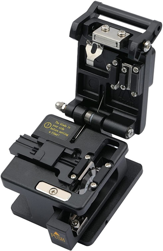
You will also need a cleaver. The cleaver precisely cuts the fiber optic cable strands so that they line up perfectly when placed inside the fusion splicer. The cleaver usually comes with the splicer. You can buy one for about $200.
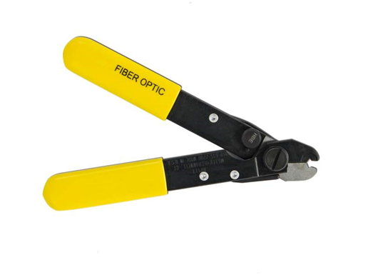
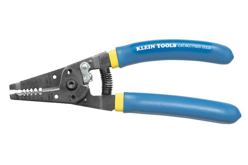
I also carry a Klein tools cable stripper for stripping copper cables and for stripping the outer jacket of a fiber optic cable. You must be careful when stripping copper cables because different cables have different outer jacket diameters. If you are not careful, you might nick the wires inside the cable. It costs about $80.
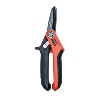
I also recommend a pair of cutters. The ones I like to use are made by Wiss, specifically the W7T model. This pair of cutters cost about $50 and can cut through almost anything.
A spectrum analyser is a device that measures Wi-Fi signals. The spectrum analyser may be a physical device or may be incorporated into a software application such as inSSIDer. The Wi-Fi spectrum analyser tells us what frequencies different access points are broadcasting on.
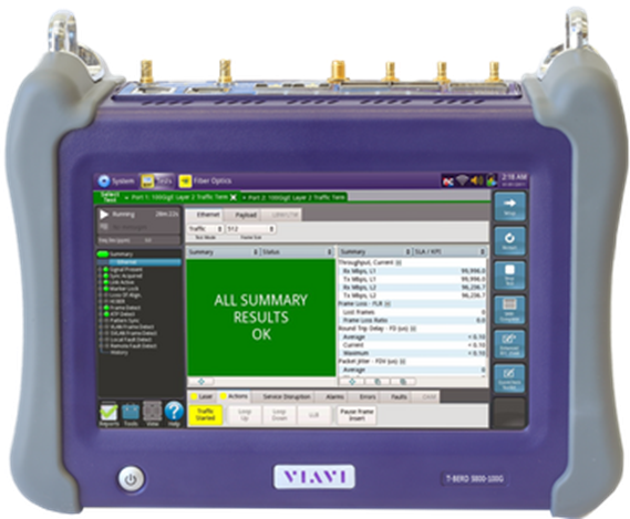
A handheld network analyser such as the JDSU T-BERD below is a more advanced tool that can test fiber and copper cables from 1 Mbps to 100 Gbps. You can connect an SFP to it as well. It is very expensive but very useful especially for testing advanced internet connections including SONET and 5G. This device costs upwards of $40,000.
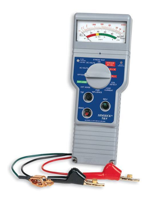
A tool that I have but rarely use is the sidekick meter below. It can test a phone line to determine whether it has the appropriate voltage under stress. Sometimes, a phone line appears to have a dial tone but does not work when you actually pick up the phone. This device costs about $1500, but I found a used one for $200.
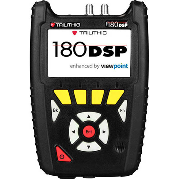
Another tool that I have but rarely use is the QAM meter. I use this for testing coaxial cable transmission systems. This device costs about $2500, but I also found a used one for $200.