
5.4 Given a scenario, troubleshoot common wireless connectivity issues
- Specification and Limitations
- Throughput
- Speed
- Distance
- Received Signal Strength Indication (RSSI) Signal Strength
- (EIRP) / Power Settings
- Considerations
- Antennas
- Placement
- Type
- Polarization
- Channel Utilization
- AP Association Time
- Site Survey
- Antennas
- Common Issues
- Interference
- Channel Overlap
- Antenna Cable Attenuation / Signal Loss
- RF Attenuation / Signal Loss
- Wrong SSID
- Incorrect Passphrase
- Encryption Protocol Mismatch
- Insufficient Wireless Coverage
- Captive Portal Issues
- Client Disassociation Issues
- Interference
Let’s look at some common Wi-Fi issues.
Older Wi-Fi access point typically sends signals (radio waves) in all directions, in the hope that some of them will land on devices that need to connect. Newer Wi-Fi access points use a technique called beam forming to make sure that they get to where they need to go.
What happens to these signals? Some of them hit reflective surfaces. A reflection means that the signal bounces back. Surfaces that cause reflection include metal and glass. A device may pick up a reflected signal, but the range of the signal will be reduced when reflection is involved.
Refraction is when a signal passes through a surface but bends. Surfaces that cause refraction include walls and doors. A device may be able to pick up a refracted signal.
Absorption is when the signal is absorbed by a surface. The signal simply disappears. Very few signals completely consume Wi-Fi signals, but most surfaces absorb a portion of the Wi-Fi signal. An absorbed signal becomes weaker.
We can improve the signal strength by installing antennas. If we install an antenna, we could improve the access point so that the signal strength is -10 dBm at the access point, -40 dBm about 100 ft away, and -70 dBm about 200 ft away.
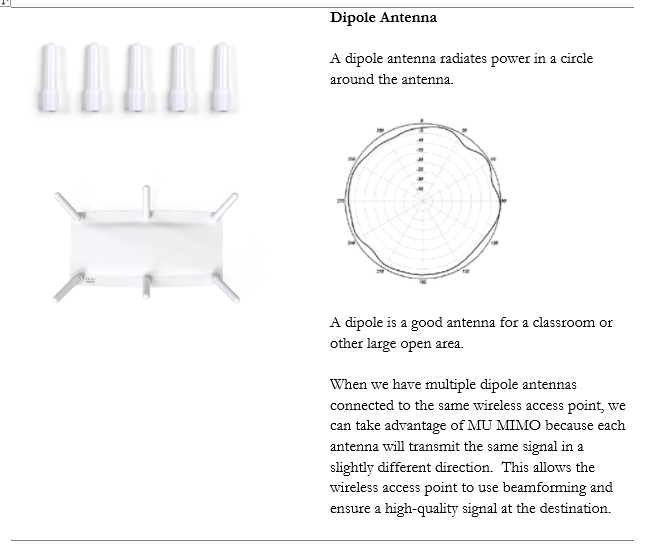
Remember that there are different types of antennas. A wireless access point will come with a built-in internal antenna, but we might need to add some external ones to improve the signal. Each type provides a signal of a different shape. If we choose the wrong antenna, we will not have the correct coverage. Even if we choose the correct type of antenna, if we point it in the wrong direction, then we won’t have the correct coverage.
For example, if we have a warehouse with tall metal shelves and long aisles, putting access points in the ceiling won’t give us a good signal. Instead, we should install antennas at the end of each aisle and point them down the aisle.
In office buildings, schools, and hospitals, we should avoid putting access points in the hallways. Instead, we should put them inside the classrooms and large open areas where the signal can spread out. If we put an access point in a hallway, the signal will tend to bounce down the wall left to right until it runs out of power.
In a wireless network, latency and jitter can be caused by poor quality access points. If the access point takes a long time to process or transmit the signal, significant latency can develop.
When the access points form a mesh network, a signal may need to travel between several access points to get from the main network to the user’s device. This also increases latency.
We also have latency due to the WAPs advertising themselves (letting users know about their SSIDs). The actual data transmission rate is called throughput. The actual beneficial throughput from an access point is called goodput.
Another item we can measure is RSSI or Received Signal Strength Indication. The RSSI value tells us how strong the wireless signal is at the device that is receiving it. Each manufacturer will use a different scale for the RSSI measurement, so we must check the score against the device’s operating manual to be able to interpret the results.
Effective Isotropic Radiated Power measures the actual power transmitted by an antenna. Consider the following. On the left, I have a Cisco wireless access point, which has four connectors for antennas. On the right, I have a Cisco directional antenna, with four antenna cables.
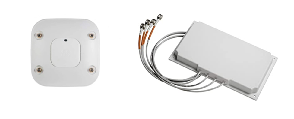
The actual radio signal generated by the wireless access point leaves those four holes, travels down the antenna cables, and is outputted by the directional antenna. If we didn’t have an antenna, the signal from the access point’s transmitter would spread across a large area and would be low. The antenna takes the signal and allows us to focus it in a specific direction.
If the access point has 10 Watts of power, and the antenna has a gain factor of 3 (it multiplies the signal by 3), then the antenna has an effective power of 30 Watts in a specific direction. That is not to say that the system has multiplied the power, since it is impossible for an antenna to create energy. Instead, what we are saying is that the antennas is focusing the power in a specific direction such that a transmitter would have required 30 Watts to accomplish the same task by itself.
It should also be noted that we will lose some power through the antenna cables. The longer the antenna cables, the greater the loss.
Let’s take a look at some antennas
When choosing an antenna, decide
- Does the wireless access point have adequate built-in antenna coverage, or do I need an external antenna?
- If I need an external antenna, what type do I need. In other words, where do I need to focus the signal?
- How much gain do I need? Different antennas have different gains.
- How will I mount the antenna?
- Make sure that the antenna supports both 2.4 GHz and 5 GHz. An antenna may have different patterns/gains for each frequency or may only support one frequency.
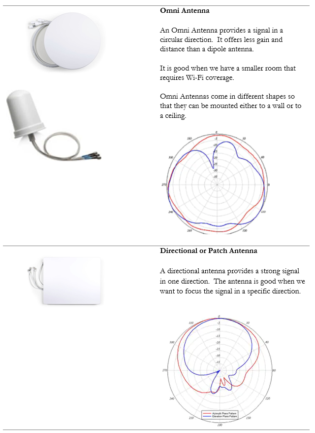
You must also consider how the antenna is polarized. The polarization is the direction that the signal leaves the antenna. If we have a directional antenna and we don’t know the polarization, then we won’t know how to mount it correctly. The signal may leave the antenna at a completely wrong angle.
We should make sure that all the antennas in our system have the same polarization. Most antennas have a linear (flat) polarization that is oriented horizontally or vertically.
Attenuation is when the signal strength is reduced. The further we get from an access point, the weaker the signal. The signal strength is also reduced by surfaces that reflect, refract, or absorb the signal.
For example, if the signal strength is -40 dBm (a good strength) at the access point, it might be -70 dBm (an average strength) about 100 ft away, and -100 dBm (a weak strength) about 200 ft away.
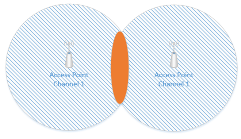
Interference is when two Wi-Fi signals cancel each other out. Consider the following access points, both of which are broadcasting on Channel #1. The signal is good, except where it overlaps, where it cancels out.
A device in the red area will see a weak signal because the access point signals are cancelling each other out. The solution is to change the channel on one of the access points.
Remember how I said that a Wi-Fi channel is 22 MHz wide and that the channels are spaced 5 MHz apart? That means that on the 2.4 GHz range, the first channel is 2.412 GHz, but it actually ranges from 2.401 GHz to 2.423 GHz. The second channel is 2.417 GHz, but it actually ranges from 2.406 GHz to 2.428 GHz. That means that channels one and two overlap. Thus, we should pick two channels that are far enough apart so that interference does not take place. The sixth channel ranges from 2.426 GHz to 2.448 GHz. In the above example, I should set one access point to Channel 1 and the other access point to Channel 6. Now the signals won’t interfere.
There are two other things we need to consider. An access point may only be able to handle fifty connections – this is an estimate for a high-quality access point; a poor-quality access point may only be able to handle twenty. If I have a conference room or theater with 200 or 400 occupants, even if the access point provides a good signal across the entire room, it may not have the capacity to connect to all the devices. We should install multiple access points to ensure that we have enough capacity. We should spread them out and give each one a different channel. We should also reduce the transmit power on each access point so that it only covers a small portion of the room.
We should install access points to ensure that the signal is at least -67 dBm everywhere. In the past, we used to aim for a -70 dBm signal strength, but as more advanced applications such as streaming video emerged, the requirements grew to -67 dBm.
We should also verify that our Signal to Noise Ratio (SNR) is at least 24. Noise is caused by wireless signals that are outside of our network. Devices such as cell phones, cordless phones, microwaves can cause noise. Other wireless networks can also cause noise. If our SNR ratio is too low, we might need to add additional access points, move the existing access points, install shielding in the building, or remove the sources of noise.
On the 2.4 GHz network, only four channels don’t overlap – 1, 5, 11, and 14. Where possible, we should limit our design to these four channels.
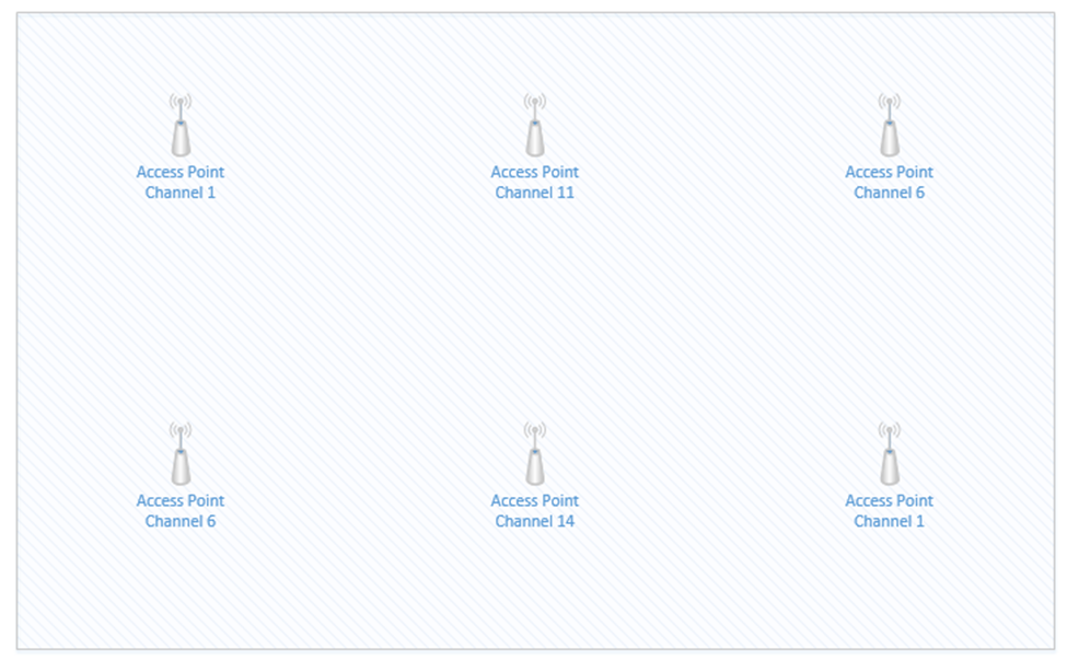
Consider this small rectangular room, which requires six access points due to accommodating many users.

If I space out the access points evenly and set them as best as I can so that there are no neighboring channels, they might look like this.
The access points that are on Channel one are in the top left corner and bottom right corner. If we highlight the coverage area of just those two access points, we can see that there is a significant overlap in the middle of the room (shown in red). The red area will have poor coverage due to interference – there will be signals from two access points on Channel one. What can we do?
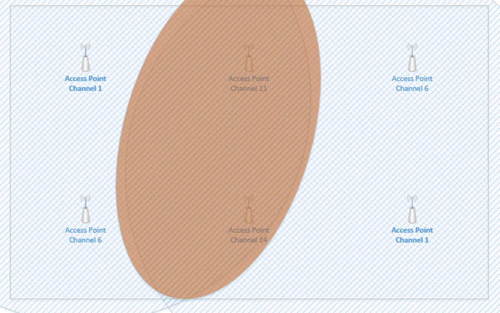
We can reduce the transmit power of each access point, so that the signal range is weaker. This way, the signals don’t overlap, but we can still cover the entire room with an adequate Wi-Fi signal.
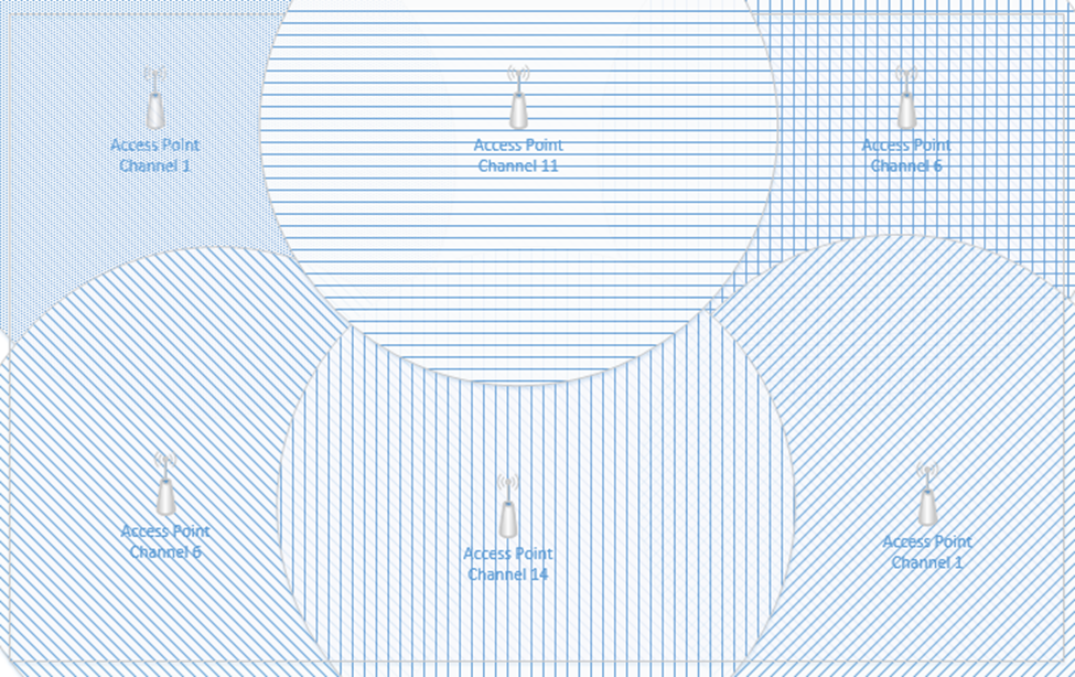
I still have overlapping signals. But the overlap doesn’t extend across the entire room. The access points that overlap are broadcasting on slightly different frequencies; therefore, their signals do not interfere.
Before we install a wireless network, we should first complete a wireless site survey. The site survey allows us to identify the following
- The areas that require wireless coverage
- The type of material that the walls are made of
- The shape and size of the room and buildings
- Any other factors that would affect Wi-Fi coverage
- How the wireless access points will be mounted
- The type of antennas required
- The type of ethernet cabling present; if no ethernet cabling is present than we can determine the best way to install new ethernet cabling
- The distance from the wireless access points to the IDF or MDF
- Whether the existing network equipment will support the addition of new wireless access points. In other words, are there available Gigabit (or 2.5 Gigabit) PoE switch ports?
At the end of the survey, we should have a plan for exactly how we are going to install the new Wi-Fi network, and where they will go.
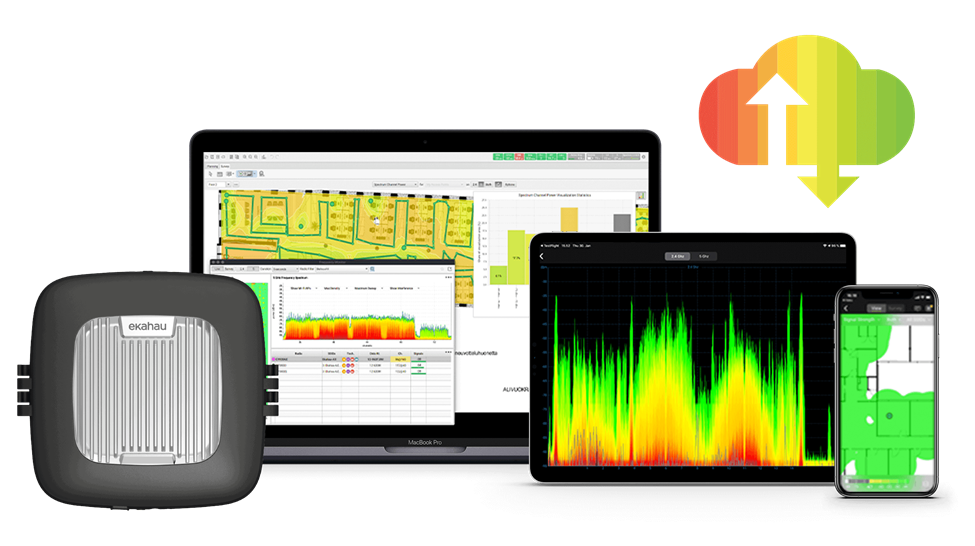
I use a software tool called ekahau. I used to use Air Magnet Survey Pro. Ekahau comes with a tool called a “side kick”. The sidekick is a device that collects Wi-Fi signals.
Let’s say we have a new building and we want to install a new wireless network. What will we do?
- We start by gathering basic information – the building floor plan, the areas that need Wi-Fi coverage, the user requirements, the security requirements, the way that the building was constructed, the types of vendors that the customer will permit (do they want Cisco, Meraki, HP, Aruba, etc.?)
- We walk around the facility to confirm the data that we gathered. We determine if there are area where wireless access points cannot be installed.
- Once we have an idea, we can import the floor plan into our survey software. We can draw out the areas that need coverage and tell the software where there are areas that will reduce coverage (such as metal shelves, concrete walls, etc.)
- We also tell the software the type of access points and antennas that we want to use
- The software runs a simulation that predicts the best spot each wireless access point. This is just a preliminary design. The software will show us a heat map that demonstrates the coverage. We can this adjust this design to add more wireless access points where there are many users (such as in conference rooms or classrooms). We can also move the wireless access points to more practical installation locations. The software adjusts the heat map each time we make a change.
- We then complete a Passive site survey. The passive site survey involves us walking around the building and collecting wireless signals automatically. The passive survey gives us a baseline idea of the noise in the environment. It should be completed during the day when many people and devices are active.
- We then complete an Active site survey. This is known as an AP on a Stick. Basically, we get a telescoping pole and mount an AP to the top, facing down. Then we power up the AP and place the stick at the first spot identified by our survey software.
We walk around and take measurements to determine whether the AP is providing adequate coverage. In other words, did the software correctly predict a good spot for the AP where we have at least -67 dBm and an SNR of at least 24?
Once we have gathered enough data, we move the AP on a Stick to the second location and take additional measurements. We continue to do this until we have placed the AP on a Stick at every location predicted by the software. - The software takes all the data that we collected and stiches it together. Then we can compare it against the original prediction. If the coverage determined during the survey is adequate, then we can proceed with installation. If not, we must make changes to the design and take additional measurements. This might be an iterative process until we get it 100% correct.
- Once we have the system installed and operational, we perform a final survey to verify that the system is operating in accordance with the original plan.
We can also survey an existing Wi-Fi network to determine whether it is operating correctly. At the end of that survey, we will have a plan to correct any issues we found.
On the user’s side a Wi-Fi connection can fail if the user attempts to connect to the wrong SSID, if the user has entered the wrong passphrase, or if he has selected the wrong type of security. The user’s computer and the Wi-Fi network must agree to the same security setting. If not, this is known as an encryption protocol mismatch.
Typically, a failure to connect will return a generic error on the user’s device but may return a more detailed error to the network administrator.
We should verify that the credentials are correct. We should attempt to clear or forget saved Wi-Fi networks and credentials. We should also update the network adapter drivers on the client device.