
3.3 Given a scenario, implement secure network designs
- Load Balancing
- Active/Active
- Active/Passive
- Scheduling
- Virtual IP
- Persistence
- Network Segmentation
- Virtual Local Area Network (VLAN)
- Screened Subnet (Demilitarized Zone)
- East-West Traffic
- Extranet
- Intranet
- Zero Trust
- Virtual Private Network (VPN)
- Always On
- Split Tunnel vs Full Tunnel
- Remote Access vs Site to Site
- IPSec
- SSL/TLS
- HTML5
- Layer 2 Tunneling Protocol (L2TP)
- DNS
- Network Access Control (NAC)
- Agent and Agentless
- Out-of-Band Management
- Port Security
- Broadcast Storm Prevention
- Bridge Protocol Data Unit (BPDU) Guard
- Loop Prevention
- Dynamic Host Configuration Protocol (DHCP) Snooping
- Media Access Control (MAC) Filtering
- Network Appliances
- Jump Servers
- Proxy Servers
- Forward
- Reverse
- Network-Based Intrusion Detection System (NIDS) / Network-Based Intrusion Prevention System ((NIPS)
- Signature-Based
- Heuristic / Behavior
- Anomaly
- Inline vs Passive
- HSM
- Sensors
- Collectors
- Aggregators
- Firewalls
- Web Application Firewall (WAF)
- NGFW
- Stateful
- Stateless
- Unified Threat Management (UTM)
- Network Address Translation (NAT) Gateway
- Content/URL Filter
- Open-Source vs Proprietary
- Hardware vs Software
- Appliance vs Host-Based vs Virtual
- Access Control List (ACL)
- Route Security
- Quality of Service (QoS)
- Implications of IPv6
- Port Spanning/Port Mirroring
- Port Taps
- Monitoring Services
- File Integrity Monitors
How can we make our network more secure?
Load Balancing
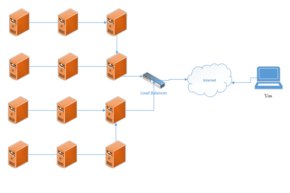
A load balancer distributes traffic among multiple resources. For example, consider that the Google.com website has only one URL (www.google.com), which would ordinarily point to one IP address. That IP address would ordinarily point to one web server. But one single web server would be overloaded by the traffic; in fact, the Google.com website has millions of web servers. The solution is to install a load balancer in front of those servers. The load balancer can distribute the incoming traffic among all the web servers.
DNS load balancing is when a domain name’s DNS records point to multiple web servers. For example, Google.com’s DNS records could point to both 11.11.11.11 and 12.12.12.12, each of which is assigned to a separate server. This would balance the traffic among two servers (which is not enough for Google). Attempting to balance millions of servers on one DNS record would not work because the customer would not have enough public IP addresses to cover all the servers in use, and the DNS record would be massive.
A load balancer uses a scheduling algorithm to determine how to distribute traffic among the servers connected to it. Consider a scenario where there is one load balancer and three servers, Server A, Server B, and Server C. There are several types of load balancing algorithms
- First Come First Served – each request is handled in the order that it arrives; when the servers are busy then additional requests are put on hold. The load balancer sends the first request to Server A, the second request to Server B, and the third request to Server C. The load balancer does not send additional requests to the servers until a server indicates that it has spare capacity (i.e. that it has completed the current request).
- Round-Robin – each request is handled in the order that it arrives. The load balancer sends the first request to Server A, the second request to Server B, and the third request to Server C. The fourth request is sent to Server A, the fifth request is sent to Server B, and so on. The round-robin algorithm assumes that all the servers have the same capacity, and that all requests are of the same size. If some requests take a server longer to process, they could overload the servers. If one server is more powerful then the rest, it could remain idle for extended periods of time (since all servers receive the same number of requests).
- Weighed Round-Robin – like round robin, but each server is given a specific weight based on its capacity. For example, if server A is twice as powerful as Server B or Server C, it can be given a weight of two, while Servers B and C are each given a weight of one. Server A would then receive twice as many requests as Server B and Server C.
A sticky session allows a load balancer to remember each client (based on their HTTP session). When a returning client is recognized, the load balancer sends that client back to the same server that they were previously connected to, regardless of the server load. This allows the server to maintain the client’s data locally (and not in a central database). This is also known as affinity.
Load balancers typically work in pairs or groups. This prevents the load balancer from becoming a single point of failure.
In a logical network topology, the load balancer is shown to be connected between the internet and the servers that it is balancing. In the physical reality, the load balancer can be connected anywhere on the network. If a load balancer has 1000 servers connected behind it, it wouldn’t have 1000 physical connections to those servers, but instead would route traffic to them over the local network. Regardless of the load balancer’s location, it must have a good network connection, typically 1 Gbps or 10 Gbps.
The group of servers connected to the load balancer can be active-passive or active-active. In an active-active configuration, the load balancer distributes the work among all the connected servers. In an active-passive configuration, some servers remain active (receive work) and some remain passive (do not receive work). In the event of a failure of one of the active servers, a passive server is activated and begins to receive work.
An active-active configuration is better because it can quickly respond to surges in traffic and allows the system to fully utilize all its resources.
In a Virtual IP scenario, the load balancer does not exist. Instead, all the servers work together to share the workload. Consider that we have three servers:
Server A has a private IP of 10.0.0.1
Server B has a private IP of 10.0.0.2
Server C has a private IP of 10.0.0.3
The public IP address is 11.11.11.11
Servers A, B, and C communicate with each other over their private IPs 10.0.0.1, 10.0.0.2, and 10.0.0.3. The servers all set 11.11.11.11 as their public IP, and then elect one server to respond to requests. For example, Server A, B, and C choose to have Server B respond to all requests on 11.11.11.11. If Server B is overloaded, it may communicate this fact with Server A and C (over their private IPs), which designate Server A to temporarily respond to requests on 11.11.11.11.
The servers continually ping each other to ensure that all the servers are functional. This form of communication is known as a heartbeat. If Server B were to stop responding within a specific period, Server A and Server C would choose to designate Server A to respond to new requests.
The algorithm used to determine which server would respond will vary from scenario to scenario.
Segregation/Segmentation/Isolation
It is important to isolate different types of data. For example, a retail store may have the following types of data on its network
- Point of Sale system information, including product inventory, transactions, and customer records, which may be shared with an in-store server and with an external server or data center such as Microsoft Dynamics
- Back office data including e-mail, sales forecasting, payroll, and scheduling, which may be shared with different cloud apps such as Microsoft Office 365, and ADP
- Credit card transaction information
- Music (retail stores use media players that automatically download music from the internet)
- Traffic counting camera system (such as Shopper Trak)
- VoIP phone system
- Surveillance camera footage that may go to an NVR or to a server (accessible by all employees or only by loss prevention)
- Wi-Fi for store-owned devices such as mobile point of sale devices
- Guest Wi-Fi
- HVAC devices
Guest Wi-Fi should not mix with any other type of traffic. Credit card transaction information should go directly to the bank and not mix with any other type of traffic (but a point of sale system must be able to communicate with a credit card terminal for creating a transaction). Third party vendors such as the music company, the VoIP company, and the traffic counting company should be able to access their own devices, but no other devices.
If each type of traffic was to be physically separated, the store would have to build a separate physical network for each class of devices. That would require a separate internet connection, router, firewall, switch, and access points, which would be expensive to maintain and operate.
A separate physical network is the second most extreme type of network segmentation after an air gap
- It is the most expensive because it requires separate hardware and wiring; operating costs are greatly increased
- Physical network separation should be used when the risk of any data leak is too high, or when the damage resulting from a data leak is too high. For example, classified information and unclassified information should never be on the same physical network.
- It may not always be possible to install a new separate physical network (there may not be enough space or adequate wiring). For example, if a retail store has
- A cash counter with one cash register
- One ethernet cable, which connects the cash register to the network equipment at the back of the store
- The store wishes to add a new credit card machine at the cash counter, which will require a separate physical network
- Even if the store could install a set of new network equipment at the back of the store, it may not be able to run a second ethernet cable to the cash counter; thus, a separate physical network may not be possible
- A cash counter with one cash register
A logical network (VLAN) is the next step, when a physical network cannot be implemented
- A VLAN is a Virtual Local Area Network
- Each network switch port can be assigned to one or more VLANs (each with a different default gateway)
- Each network device can be assigned to a different VLAN
- A device on one VLAN cannot communicate with a device on another VLAN (even if they are on the same switch and even switch port), unless it goes through a gateway. The gateway can permit or deny the traffic.
- A VLAN allows multiple types of devices to coexist on the same set of network equipment
- In the example of the retail store, each type of device (point of sale, back office, surveillance cameras) can be on a different VLAN. The store can set rules for if and how devices can communicate with each other.
- A VLAN requires the use of a managed switch. Unmanaged switches cannot be configured to accept traffic tagged with VLANs.
An air gap is the most extreme type of network segmentation. A single device can be air gapped or a large network can be air gapped. An air gapped system is one that is not physically connected to any other network.
Air gapping is necessary when the harm from compromise greatly outweighs the cost of the air gapping. For example, a nuclear power plant’s control system should be air gapped. An air gapped computer should have its network interfaces physically removed where possible. Remember, it is impossible to predict when or how a network device is compromised. Security holes exist in everything and it is always possible that a device known to be secure contains a major flaw.
As mentioned earlier, when we can’t physically separate a device, we put it inside a demilitarized zone or DMZ. The DMZ is now called a Screened Subnet.
The DMZ is a zone where devices that need to access the internal and external network can be placed.
Hosts that require internet access and that are vulnerable to attack (such as e-mail servers, web servers, and VoIP servers) should be placed in the DMZ.
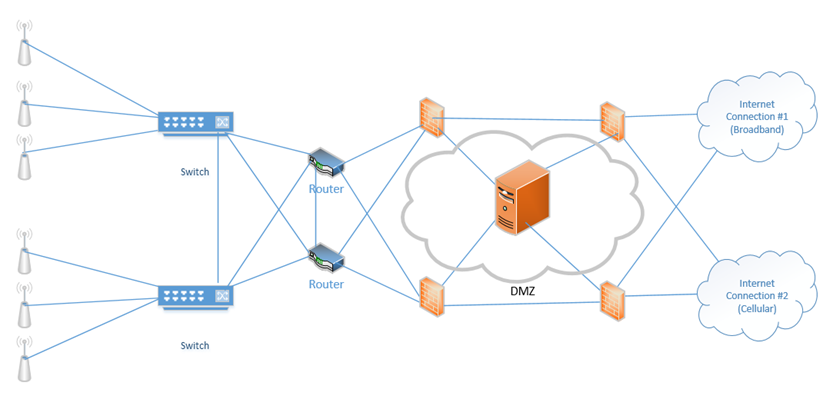
The best setup is to install a firewall between the internet and the DMZ, and another firewall between the DMZ and the internal network.
Always assume that a device in the DMZ has been compromised. Building on the concept of our redundant network from earlier, now we have installed a DMZ, and one server within the DMZ. The firewalls on the right protect our DMZ servers from external threats, and the firewalls on the left protect our internal network from external threats and potential threats from the DMZ.
Traffic moving up from the infrastructure layer to the application layer is considered moving “north” while traffic moving from the application layer down to the infrastructure layer is moving “south”. Traffic moving between devices is considered moving East-West (i.e. from server to server).
An Intranet is a website that is only accessible from inside the corporate network. Most large organizations maintain an intranet with information on projects, human resources, health and safety, etc. An Extranet is a subset of the intranet that is accessible to customers, vendors, and others. We may host the Intranet in the DMZ.
Zero Trust is a new concept that tells the network not to trust anything regardless of whether it is inside the network or outside. Any device connected to the network must prove that it is worthy of accessing a resource. In a way, it is an idea of installing a firewall between the internal users and the network, not just between the internet and the network.
The Zero Trust system works at Layer 7. It must deeply examine the data that is being transferred, not just the source and recipient.
Virtual Private Network (VPN)
A VPN is a Virtual Private Network. It allows a remote user (working from home, a hotel, a hotspot, etc.) to connect to a corporate network through a tunnel. Essentially, the traffic from the user’s computer is packaged and sent through a tunnel to the corporate network. If the user attempts to access a website, that request is sent to the corporate network. The corporate network sends the traffic to the website. It takes the traffic that it received from the website and sends it back to the user through the VPN. Therefore, traffic received from the user appears to be coming from the corporate network, regardless of the user’s location.
A VPN “tricks” the user’s computer into thinking that it is on the corporate network so that the user can access resources such as internal applications, shared drives, and printers.
A VPN concentrator is a device that collects and manages VPN connections from multiple users and passes their traffic to the LAN. It could be hardware-based or software-based. The VPN concentrator functionality can be incorporated into another network device such as a router.
VPN functionality is incorporated into devices such as
- Cisco Routers
- Cisco ASAs
- Fortigates
- Sonicwalls
- Cisco Meraki Routers
Remote users can use software to establish VPNs (such as Windows VPN or Cisco AnyConnect) or can install hardware-based VPN appliances such as Meraki Z3.
Features of the VPN can include
- Remote Access vs. Site-to-Site. A Remote Access VPN allows users to connect back to a corporate network, typically through their computer. A Site-to-Site VPN allows two offices to connect to each other and pretend like they are part of the same physical network. A Site-to-Site VPN typically applies to the site’s router and not to individual devices on the network.
- The performance on a VPN is affected by the quality of the user’s internet connection, by the quality of the corporate network’s internet connection, by the number of active users, and by the type of resources being accessed.
- When there are multiple sites that need to be connected, a site-to-site VPN should be replaced by a WAN. A WAN is more expensive but offers better performance.
- The performance on a VPN is affected by the quality of the user’s internet connection, by the quality of the corporate network’s internet connection, by the number of active users, and by the type of resources being accessed.
- IPSec. IPSec is a set of protocols that allow hosts to exchange packets securely. IPSec has several modes of operation, including
- Tunnel Mode. The Tunnel Mode encrypts the source, destination, and contents of every packet. Essentially, it establishes a secure tunnel between two network devices where data can travel securely. The devices that are establishing the tunnel are not necessarily the devices that are creating the traffic. For example, a router is sending traffic on behalf of a server inside the network. An outsider will not be able to examine the source, destination, or contents of any traffic.
- Transport Mode. The Transport Mode only encrypts the contents of the packet. It does not encrypt the source or destination. An outsider will be able to examine the source and destination. Transport Mode is established by the two network devices who are communicating, and not by the routers on the edges of the network.
- SA. An SA, or Security Association is an algorithm and key that are used to encrypt traffic in an IPSec tunnel. Each direction of communication requires a separate SA. Therefore, most IPSec tunnels will require two SAs.
- There are four methods of connecting a tunnel. Consider that two computers (each inside a separate network and behind a router) would like to communicate securely across the internet. How can an IPSec tunnel be established?
- Machine-to-Machine. Two computers (or smartphones) establish a tunnel and communicate. This is not practical because each computer will expend a substantial amount of computing power encrypting and decrypting the IPSec traffic.
- Router-to-Router. It is assumed that the connection between the computer and the router (on the internal network) is secure. The routers establish an IPSec tunnel. The computers no longer encrypt traffic between themselves and the routers. The routers encrypt all traffic between themselves.
- Machine-to-Machine and Router-to-Router. This combines the previous two scenarios. Each machine establishes an IPSec tunnel with the router on its network, and the routers establish an IPSec tunnel between themselves.
- Remote User. A remote user connects to a router through an IPSec tunnel, and then establishes a secondary IPSec tunnel to connect to a device deeper in the network.
- Machine-to-Machine. Two computers (or smartphones) establish a tunnel and communicate. This is not practical because each computer will expend a substantial amount of computing power encrypting and decrypting the IPSec traffic.
- Tunnel Mode Encryption. The tunnel mode is the method for encrypting the traffic. Consider that two routers have created an IPSec tunnel and that behind each router is a computer that wants to communicate. What is the order of operations?
- The computer generates some data and places it in a packet.
- The computer puts the address of the remote computer in the header of the packet (or the address of the network that it is sending it to, when the network employs NAT – more on this later).
- The computer sends the packet to the router
- The router encrypts this packet, including the headers
- The router encapsulates this packet inside a larger packet and adds the recipient’s router address to the header
- The router sends the packet to the destination router
- The destination router removes the outer header, decrypts the packet, and forwards it to the computer inside its network
- Neither computer is aware of the existence of the IPSec tunnel
- The computer generates some data and places it in a packet.
- Tunnel encryption works through the following security protocols
- AH. Authentication Header. When AH is used, the original IP header (created by the computer that generated the data) is visible to outsiders, but the contents are protected. AH protects the integrity of the data. That is, the recipient can be sure that the sender listed on the packet is in fact the true sender.
- ESP. Encapsulating Security Payload. ESP encrypts the contents of the data, but it does not guarantee integrity.
- It is recommended to use both AH and ESP, thereby providing privacy and integrity.
- AH. Authentication Header. When AH is used, the original IP header (created by the computer that generated the data) is visible to outsiders, but the contents are protected. AH protects the integrity of the data. That is, the recipient can be sure that the sender listed on the packet is in fact the true sender.
- IPSec algorithms
- IPSec is a framework for exchanging data, but the contents of the framework vary from vendor to vendor and network to network. Just like there can be many different models of vehicles on a road, all following the same traffic rules, there can be many different types of algorithms to exchange data within a tunnel.
- Many different encryption algorithms can be used. This flexibility allows an algorithm to be replaced when it is discovered to be weak.
- Methods include
- Diffie-Hellman key exchange with public key signing
- MD5 and SHA-1 hashing algorithms to ensure data integrity
- Diffie-Hellman key exchange with public key signing
- IPSec is a framework for exchanging data, but the contents of the framework vary from vendor to vendor and network to network. Just like there can be many different models of vehicles on a road, all following the same traffic rules, there can be many different types of algorithms to exchange data within a tunnel.
- IPv4 vs IPv6. IPSec is integrated into all IPv6 packets by default, but not IPv4 packets. When IPv4 was designed, security was not a primary consideration. As the internet grew, the design of IPv6 required security to be integrated into all communications. A device can use IPv6 and not activate the IPSec feature however.
- Tunnel Mode. The Tunnel Mode encrypts the source, destination, and contents of every packet. Essentially, it establishes a secure tunnel between two network devices where data can travel securely. The devices that are establishing the tunnel are not necessarily the devices that are creating the traffic. For example, a router is sending traffic on behalf of a server inside the network. An outsider will not be able to examine the source, destination, or contents of any traffic.
- L2TP (Layer Two Tunneling Protocol)
- L2TP was a tunneling protocol that was developed in 2000.
- L2TP does not provide encryption but the tunnel can be carried by the IPSec protocol, which operates on Layer Three.
- Effectively, the two parties use L2TP to create a VPN tunnel between themselves. This tunnel is used to pass data.
- Then the two parties use IPSec to agree on an encryption scheme and encrypt the data that they send over the L2TP tunnel.
- L2TP was a tunneling protocol that was developed in 2000.
- Split Tunnel vs. Full Tunnel
- In a Full Tunnel VPN, all traffic is routed through the VPN, but in a Split Tunnel VPN, only specific traffic is routed through the VPN.
- The advantage of a split tunnel is that it reduces bottlenecks. Consider a corporate user working from home. The user needs to access network resources such as a shared drive and corporate finance applications. This traffic must go over the VPN. The user is also watching YouTube videos. There is no reason to route YouTube videos over the corporate network (requiring encryption on both sides). YouTube traffic can travel over the user’s home internet connection.
- In a Full Tunnel VPN, all traffic is routed through the VPN, but in a Split Tunnel VPN, only specific traffic is routed through the VPN.
- TLS. In addition to providing internet security, Transport Layer Security is an alternative to IPSec VPN. A TLS VPN is useful when the network uses NAT.
- Always-On VPN. An Always-On VPN is just like it sounds. It is a VPN that is always on. Typically, an Always-On VPN is part of a hardware appliance, but it could also be software-based. When the VPN detects an active internet connection, it automatically attempts to re-establish the VPN.
For security purposes, an Always-On VPN can block traffic from travelling over the internet when the VPN gets disconnected. This would prevent a user from inadvertently disclosing his true location. - HTML5. An HTML5 VPN is a new concept. Since HTML5 supports cryptography, we can build a VPN application that runs through a web browser. That means that we can build an internal web application, and have external users connect to it through a VPN login without having to install any software or making configuration changes to their computer. All they require is a web browser.
Of course, there are limits on what a web-based application can do.
DNS
Remember that a computer understands addresses in numeric format (like 8.8.8.8) and a human understands text (like google.com). How does the computer know where google.com is (i.e. the IP address of the google.com server)? We use the DNS (Domain Name Service) to convert the human-readable address into a computer-readable address.
When I try to visit google.com, my computer calls up the nearest DNS and asks it to provide information about google.com. google.com is known as a domain name or a hostname. A DNS will contain a set of records about each domain name. Those records are given to the DNS by the owner of the name. The records for the domain is called a record set. What kind of information can it provide?
- A or AAAA. The A (Address Mapping) record tells us the IPv4 address of the server that is hosting the domain name. The AAAA record tells us the IPv6 address that is hosting the domain name.
- TXT (SPF, DKIM). The TXT (Text) record tells us some text. Two common uses of TXT records
- SPF or Sender Policy Framework. Think of an e-mail like a letter. It has a “to” address and a “from” address. I could send a fake letter and use a fake “from” address because nobody can verify that the “from” address is correct. An e-mail is the same. A spammer could spoof the “from” address and make it look somebody legitimate sent the e-mail. How can we stop this?
If the legitimate sender has control over his domain name and server, he can create a Text entry called the SPF and put the IP address of his e-mail server in there. Then when we receive an e-mail from that sender, we can verify that it came from an e-mail server with an IP address matching the record.
When a recipient receives a message, he checks the IP address in the SPF belonging to the legitimate sender. If it matches the actual sender, then he knows that the e-mail is legitimate.
- DKIM or DomainKeys Identified Mail is another way to identify an e-mail’s legitimate sender. A user of DKIM creates a unique signature via public key cryptography. It’s essentially a signature that can’t be forged – it has two parts, a private key that only the sender knows, and a public key that recipients can use to verify his identity. The legitimate sender places a copy of the public key in DKIM. He uses the private key to digitally sign every e-mail he sends. When a recipient receives an e-mail, he verifies that the signature in the e-mail matches the public key in the record.
- SPF or Sender Policy Framework. Think of an e-mail like a letter. It has a “to” address and a “from” address. I could send a fake letter and use a fake “from” address because nobody can verify that the “from” address is correct. An e-mail is the same. A spammer could spoof the “from” address and make it look somebody legitimate sent the e-mail. How can we stop this?
- SRV. The SRV (Server) record tells us about the location of servers that operate specific services. The server location includes an IP address or domain name and a port number. The domain name in an SRV record must itself have an A record in its own DNS record set or else it won’t be located.
- MX. The MX (Mail Exchanger) record tells us the IP address or domain name of the mail server that receives e-mail on behalf of the domain. If my e-mail is hazim@hsmservices.ca and I host my own e-mail, then the record may point to my own server. If my e-mail is hosted by Gmail for example, my MX record may point to gmail.com.
When you send an e-mail, your e-mail program (or SMTP server) will query the MX records for each recipients’ address so that it knows where to send the message.
The domain name in an MX record must have its own record in its own record set, or else it won’t be located. - CNAME or Canonical Name points one domain name to another. The purpose of a CNAME record is to point one name to another. The CNAME record must itself have an A name record.
For example, foo.example.com can point to bar.example.com. bar.example.com must have an A record in its own record set or else it won’t be located.
When a computer receives a CNAME reply, it must then look for the corresponding A record. - NS or Name Server. The NS record tells us which DNS server is authoritative for the domain. The owner of a domain name maintains DNS records for his name on an authoritative name server. The authoritative name server has the most accurate records for that specific name. A name server can be authoritative for one or more domain names.
Since the internet is distributed, DNS servers operated by other users might copy the records from the authoritative name server and respond to queries from devices close to them. When you access a website, your computer won’t necessarily query the authoritative name server for that site. It may query a local nameserver operated by your organization or ISP. - PTR or Pointer Record. A Pointer record allows a user to perform a reverse DNS lookup. PTR Records are stored under the IP address of the server, not the domain name.
- SOA or Start of Authority Record. The SOA gives us information about which DNS is authoritative for the domain. When our domain name server wants an update to the record, it checks the SOA to determine which DNS server to check.
The SOA contains a serial number. Each time the DNS record is updated, the SOA serial number is increased by one. When a client wants to transfer its DNS record to another server, it checks the serial number first. If the server does not have the current version of the record, then the transfer is authorized. This is known as a Zone Transfer.
A Reverse DNS lookup is when we have an IP address and want to know which domain name it belongs to. An IP address may belong to multiple domain names. The PTR record is used for the Reverse DNS lookup.
We can obtain the domain name corresponding to an IP address by querying the domain name in-addr.arpa. If we want to know the domain name for the IP address 1.2.3.4, we would query the name:
4.3.2.1.in-addr.arpa
Notice that we prepended the IP address in reverse to the front of the in-addr.arpa domain name. This is opposed to the Forward DNS lookup that we come to expect.
To provide load balancing and redundancy, each DNS record can contain multiple entries. We can give each entry a different priority. For example, we might have multiple servers to handle our e-mail or website hosting. In case one server is down or can’t handle the traffic, then the other servers can run.
An internal DNS is one that is operated by an organization for use on its internal network. A network might have devices that are accessible internally such as servers, switches, and printers. Each device is assigned a unique hostname on the network. The internal DNS server provides users with DNS records corresponding to these internal devices. A user may need to access both internal devices and external hosts. Therefore, the user may need to program his computer to query both an internal DNS server and an external DNS server. The external DNS provides information about hosts that are available to the public (on the internet). It is possible for an internal DNS to also be an external DNS.
An organization may choose to host its DNS with a third party. Examples of third-party DNS include Amazon (AWS) Route 53 and CloudFlare. A third-party DNS is scalable and can provide inquiries to many users at the same time. In addition, a third-party DNS is centrally located so that updates to the DNS propagate across the internet quickly.
The hierarchy of a DNS starts at the root domain name server. There are only 13 root servers. The servers provide responses to the “root” domain (i.e. .com, .net, .org). When a computer looks up a domain name, it starts at the right side and looks up the authoritative name server for the root.
Then the computer checks the authoritative server, which is maintained by the owner of the domain name. Below the authoritative server are servers operated by national internet service providers. They aggregate DNS records from the different authoritative servers. Below them are servers operated by local ISPs. Below them are servers operated by organizations for local networks.
When we query a DNS server, we might start at the local level. If the local server doesn’t have an answer, we check at the next level. If it doesn’t have an answer, we continue working our way to the top until we reach the authoritative server.
In a recursive DNS search, your computer makes a query with the DNS server. If the DNS server doesn’t have an answer, it checks the next higher up server (and up and up) until it finds an answer. It might cache the answer in case other computers request the same DNS record.
In an iterative DNS search, your computer makes a request from the DNS server. If the DNS server doesn’t have an answer, it gives your computer the IP address of the higher up server. Your computer then makes the query with the higher up server. If it doesn’t receive an answer, it continues to make queries up the DNS chain until it reaches the authoritative server.
Each DNS record has a TTL or Time To Live. This is a number that tells the non-authoritative DNS servers the length of time (in seconds) until a record expires. For example, if a TTL is 3600, then the DNS record expires after one hour. If my local DNS server obtains authoritative DNS records from google.com’s DNS, and the TTL is one hour, then it should check with the google DNS again for updated records after one hour. The TTL is set by the authoritative name server. The process of maintaining local DNS records is called DNS caching.
If we make the TTL long, then any changes will take a long time to propagate across the entire internet. If we make the TTL short, then changes will propagate quickly, but our DNS server will experience more queries because lower level name servers are requesting updates more frequently.
Network Access Control (NAC)
NAC stands for Network Access Control. NAC can be a combination of software, hardware, and policies.
NAC is used to grant access to specific users and specific locations. NAC policies can include
- Who can access the network?
- What resources are they allowed to access (printers, shared drives, servers, VPN)?
- What computers are they allowed to use to access the network (corporate-owned computers only vs personal computer)?
- What times are they allowed to access the network?
- Can they access the network from foreign countries, from home, from specific IP addresses, or only inside the network?
NAC can be permanent or dissolvable. A permanent NAC (also known as a permanent agent or persistent agent) is installed on the client and does not get uninstalled. The client uses the NAC to connect to the corporate network. The NAC may be a combination of VPN software, a security certificate, or other corporate software.
The dissolvable NAC is one that is automatically installed when a connection starts and uninstalled when the connection is complete. A dissolvable NAC may be used for contractors/visitors who require temporary access to the network, or for employees who are bringing their own devices to work.
During a connection attempt, the NAC checks the policy server for the policies required by the device. The policies may be company-wide or tailored to the type of device (laptop, desktop, cell phone) or tailored to the type of user. For example, the organization may only permit remote users to connect to the network through a VPN. The organization may only permit devices with strong passwords and disk encryption to connect to the network.
The NAC verifies that the device is compliant with all the policies. If not, the NAC could either trigger an alert but allow the connection, deny the connection, prompt the user to change their settings, or automatically change the user’s settings.
Policies can include
- Ability for the organization to remotely erase data on the device
- Device encryption settings (for data stored on the device)
- Device encryption settings for communication
- Up-to-date antivirus software
- Enforcement of specific password policies and two-factor authentication
A NAC can also be agentless. An agentless NAC is one that does not include software on the client device. An example of a permanent agent NAC is VMWare Boxer. VMWare Boxer is an application that a user must install to access sensitive corporate resources through their personal phone. The Boxer application encrypts all the data, allows the organization to monitor use of the device, and can erase all device data if necessary. Another example of a NAC is Microsoft Intune.
An example of an agentless NAC is Active Directory group policy. An administrator sets group policies on an Active Directory Domain Server. Each time a device connects to the server, it downloads the required policies and changes its policies to match what is on the server. The device checks the Active Directory Domain Server for policy updates every three hours.
In general, an organization has the legal right to monitor and record all activity that takes place on a company-owned device (such as a cell phone or computer). For best practices, the employees should consent to the monitoring.
A company will have limited rights to monitor or record activity that takes place on a device owned by an employee or contractor, even if that employee consents. An organization could be liable for behavior such as
- Monitoring or recording an employee’s personal phone calls, e-mails or web activity
- Erasing an employee’s personal information (such as text messages or photographs)
- Monitoring the location of an employee’s personal device outside of work hours
Out-of-Band Management
What if there is a problem with the router that brings down the network we can no longer access it remotely? Or what if we need to perform an operating system upgrade on a switch or server, which causes it to reboot? We need a back up method to get in. This is called out of band management.
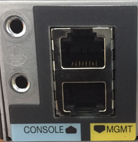
Looking at a piece of network equipment like a Cisco Router or Cisco Switch, there are three ways to get into it
- The physical console port. The physical console port looks like an ethernet port, but requires you to connect the device to your computer via a special cable known as a console cable, which has a special pin out. To use the console port, an administrator must be physically present at the device.
- The management port. The management port allows you to connect an ethernet cable to the switch. We should set up a management VLAN and connect the various management ports to it. The management port will then be configured to have an IP address on that VLAN.
- Remote access through SSH or Telnet. Telnet is not secure and not recommended. Telnet and SSH operate over the existing physical network that the devices are connected to.
So what?
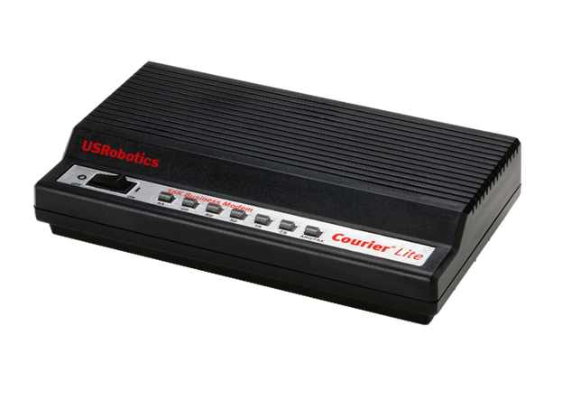
- If we have only one network device, we can connect the console port to a special 56K dial-up modem. The most popular modems are made by US Robotics and are still quite common. The modem allows us to connect to the network equipment even if the network is down or the internet connection is down. Only a phone line is required.
- When we have many devices, we can install what is known as a console server. The console server looks like a normal switch. We connect a normal ethernet cable between the console port on each device and the console server. The console server can be configured to communicate with each console port.
We connect the console server to the internet, and now we can remotely connect to the console server, and then use it to connect to and configure the network devices. It is recommended that we use a separate internet connection.
This can get tricky when the network is large and widespread because the various IDFs may not connect via copper, only fiber. Thus, there may not be a copper link between the location where the switch is and the location where the console server is.
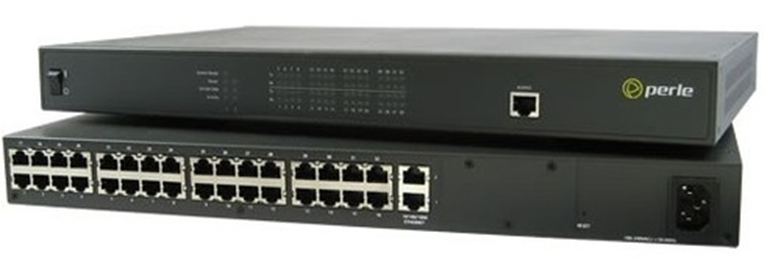
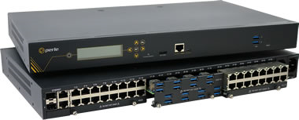
The perle console servers include the following features
- Modular design, which allows us to substitute ethernet style ports for USB ports. That means we can have remote USB access to a device.
- Built in cellular modem that provides remote access to the server without having to connect a separate modem.
- We can set up a separate physical network for the management. This might take a substantial amount of equipment to create. And the question becomes, how do we manage the devices on the management network?
That covers network devices. But what about servers? What if we need to remotely upgrade the operating system of a server or want to remotely change the BIOS settings? On the back of many servers, you will find a “remote access” port. On a Dell server, it is known as an iDRAC port, and on an HP server, it is known as an iLO (Integrated Lights Out) Port.
This “port” is actually a card that fits inside the back of the server. The card is a small modular computer, like a server within a server. It connects to the ethernet network (which can be the same network, a separate management VLAN, or a separate physical network) and allows us to remotely connect to the server.
If we have many servers, we can configure the remote access port to connect to a central server where we can manage the equipment. iLO and iDRAC are not free and require licenses to use more advanced features.
Out of band management is becoming less popular. As people switch to cloud-managed devices such as Cisco Meraki, or SD-WAN devices such as the velocloud, or serverless architecture for their applications, or software defined networking, they are removing the out of band management devices. The physical out of band management is being replaced by a management VLAN.
Port Security
There are some important security features we must enable when configuring a network switch. They might collectively be known as Port Security.
- Broadcast Storm Prevention. A broadcast storm happens when too many broadcast packets are sent at the same time. Remember that a broadcast packet is one that a switch forwards to all the members of the broadcast domain (all of the devices in the VLAN where the broadcast packet originated).
A broadcast storm can be created by a loop in the switch.
If we break up larger VLANs (VLANs with many devices) into smaller VLANs, this will reduce the size of the broadcast domain.
We can also set a broadcast packet rate limit.
- Loop Prevention. A loop within the same switch or between multiple switches is bad. When it happens, a frame can circle between switch ports or switches forever, eventually causing the switch to crash.
Most managed switches have a feature that automatically detects a loop and shuts off the affected ports.
When we have a large network, with multiple interconnected switches, we may have multiple pathways for redundancy. But these pathways are also loops that can cause the switches to crash. Cisco switches have a feature called Spanning Tree Protocol, which automatically detects the network topology and turns off any redundant pathways, ensuring a loop-free connection. If a link fails, Spanning Tree Protocol automatically activates another pathway. Now we can have redundant pathways but not have to worry about loops.
- Bridge Protocol Data Unit (BPDU) Guard. Switches learn about each other’s topology through the use of BPDU (Bridge Protocol Data Units). A BPDU is only received on a port that is connected to another switch, not a port that is connected to a user device.
A hacker could attempt to influence a switch by sending a normal port a BPDU. If the switches assume that he is also a switch, they will send him their traffic. This is bad. We can enable BPDU Guard on any port that should not be part of the topology. This will prevent those ports from switching over. - Dynamic Host Configuration Protocol (DHCP) Snooping. Remember that a hacker could install a rogue DHCP server on our network and give out invalid IP addresses or force devices to forward their external traffic to the wrong gateway?
That is because when a device requires an IP address, it sends out a DHCP message. If the rogue DHCP server responds with IP address information prior to the legitimate DHCP server, then the device will be compromised.
What we do is tell the switch which port is connected to the legitimate DHCP server. This is known as a trusted port. All the other ports are untrusted. The switch will assume that any DHCP Offer messages entering an untrusted port have originated from a rogue DHCP server, and it will not forward them.
On an untrusted port, the switch will accept DHCP messages from clients. These messages include the DHCP Discover message. Thus, anybody can ask for an IP address, but only the legitimate DHCP server can reply.
The switch creates a table called the DHCP Snooping Binding Table. Each time a client accepts a DHCP Offer, the switch creates an entry in that table. It records the MAC address of the client and the IP address that was assigned to it. It also records the VLAN and interface that the client is connected to.
Say your computer’s IP address is 10.5.5.5, and I’m a hacker. I want to kick you off the network, so I send the DHCP server a release message saying, “release IP address 10.5.5.5”. The DHCP server will normally release the IP address and try to assign it to somebody else, which will disrupt your network connection.
DHCP snooping can protect against this kind of attack as well. When the switch sees a new DHCP Release message, it checks that message’s sender’s MAC address against the table. It will see that the request to release 10.5.5.5 came from my MAC address instead of yours. It knows that the message isn’t valid and doesn’t let it through.
A hacker might try to lease many hundreds or thousands of DHCP addresses so that nobody else can get any. The switch can protect against this as well. If a client sends a Discover or Request DHCP message, the switch checks its MAC address (the MAC address inside the Ethernet header) against the MAC address inside the actual message. Remember that a DHCP message is something like “hey, my MAC address is aa:bb:cc:dd:ee:ff, can I please have an IP address”. This message is encapsulated inside an IP packet which is encapsulated inside an Ethernet frame. If the MAC address sending the message is different from the MAC address inside the message, then the switch knows something is wrong, and doesn’t let it through. - Dynamic ARP Inspection. Remember that a rogue device can send out false ARP messages. For example, if I want to intercept documents going to the printer, I plug in a fake device and pretend that it is a printer. I send out ARP messages with the MAC address of the printer.
If we turn on the DHCP Snooping, then the switch knows which IP address belongs to which MAC address (due to the binding table). We can also turn on the Dynamic ARP Inspection and force the switch to block any ARP messages that don’t match what is in the table.
If a device has a static IP, then it won’t make a DHCP request and neither its IP address nor its MAC address will appear in the table. Thus, devices such as cameras and printers, which have static IP addresses, can be subject to ARP spoofing.
A good countermeasure is to set up DHCP reservations for such devices in the DHCP server. These devices will then continue to receive the same IP addresses, but their MAC address and IP address will be recorded in the DHCP table.
- Media Access Control (MAC) Filtering. A switch port can be configured to
- Allow traffic from a single MAC address. In an ideal scenario, each switch port should see incoming traffic from only one MAC address. For example, if a printer is connected to switch port number four, only traffic from the printer should appear on switch port 4.
- Allow traffic from a limited number of MAC addresses (for example, traffic from up to ten unique MAC addresses is permitted). For example, a user may have only one data jack in their office but must connect multiple devices such as printers and computers. The user would install a small switch in their office. The larger switch would see the MAC address of the small switch and the MAC address of the devices that are connected to the smaller switch. If the switch sees traffic from say eleven MAC addresses on the same port, the switch shuts down the port.
- Allow traffic from an unlimited number of MAC addresses. Sometimes users connect and disconnect devices randomly and administrators do not want to be forced to shut down and reopen ports all the time because it can be a drain on their resources and cause disruption to their networks. Therefore, some administrators do not enforce the MAC address rule at all.
- Allow traffic from a single MAC address. In an ideal scenario, each switch port should see incoming traffic from only one MAC address. For example, if a printer is connected to switch port number four, only traffic from the printer should appear on switch port 4.
When a switch detects a violation of the MAC address rule, it can
- Place a warning in the log
- Shut down the port, in which case no devices will be permitted to connect to that specific port
Network Appliances
There are several types of network security appliances.
A Jump Server is a device that has access to two or more security zones. If a device is in a different security zone from us, we can use the jump server to connect to it. The jump server is hardened to make it resistant to attack.
We configure all of our servers and network devices to have block access to external users except for the jump server. When we want to configure a server or network device, we must log in to the jump server, and then “jump” to another device.
We can log all access to the jump server. We can also use the jump server to enforce permissions.
A proxy or proxy server is a device that masks the true source of an internet connection. There are several types of proxies
An anonymous (forward) proxy hides the source of the internet connection. For example, if a user visits Google through an anonymous proxy, Google’s servers will see the IP address of the proxy as originating the connection, and not that of the user’s PC. A popular website (such as Google) may see thousands or millions of requests from the same proxy and may choose to block them to avoid the risk of abuse or SPAM.
A transparent (forward) proxy does not hide the source of the internet connection. For example, if a user visits Google through transparent proxy, Google’s servers will see the IP address of the proxy as originating the connection but will also see the IP address of the user’s PC. A transparent proxy can be used to cache a website. By caching a website, a transparent proxy reduces traffic on a network.
A reverse proxy sits in front of a set of web servers. Consider that a website may have a single IP address, but multiple (even millions) of web servers. The reverse proxy filters incoming requests and forwards them to the appropriate server. A reverse proxy can
- Provide load balancing
- Encrypt data between the proxy and the user’s PC
- Compress web content
- Cache static web content
A proxy can be used to
- Cache web content
- Filter/restrict users from accessing inappropriate web content
- Block malware and viruses
- Allow users to access web content that is blocked in their geographic location
- Eavesdrop on all content transmitted over the internet connection
In a large network, a proxy should be configured to prevent access to malicious websites and enforce the organization’s acceptable use policy.
A NIPS is a Network-Based Intrusion Prevention System, and a NIDS is a Network-Based Intrusion Detection System.
A NIDS can only detect unauthorized access, but a NIPS can detect and react to the unauthorized access.
NIPS and NIDS have the following characteristics:
- Signature-Based: Similar to an antivirus program, a NIPS can detect an intrusion based on its “signature” or specific characteristics. For example, an intrusion enters through a specific port or from a specific source IP address. A signature-based NIPS/NIDS will not detect attacks that are zero-day or attacks that don’t match the signature.
- Heuristic/Behavioral: Like an antivirus program, a NIPS can detect an intrusion based on the way it behaves, more like artificial intelligence. A heuristic-based NIPS can detect zero-day attacks but has a higher rate of false positives.
- Anomaly. An anomaly-based NIPS/NIDS compares new traffic against a baseline. The NIPS/NIDS calibrates itself to understand normal network behavior, and then compares new traffic against that calibration. Traffic that does not match is denied.
- Inline vs Passive. An inline sensor sits between the internet and the internal network. All traffic passes through the sensor, which decides if it should be permitted or denied. An inline sensor can turn off the flow of bad traffic. If the inline sensor is overloaded, it can reduce the speed or capacity of the network. A passive sensor sits on the network but receives a copy of the traffic. A passive sensor cannot turn off the flow of bad traffic.
- In-Band vs Out-of-Band. An in-band sensor is a complete system that monitors traffic and decides whether to allow or prevent it. An out-of-band sensor monitors traffic and sends results to another system that decides whether to block it.
- Rules. Rules are decision making processes that the NIPS/NIDS uses to determine whether the traffic should be permitted or denied. NIPS/NIDS can be preloaded with rules, and an administrator can add additional rules as needed. A NIPS/NIDS with heuristic behavior can automatically create additional rules based on its findings.
- Analytics
- False Positive. A false positive is when a NIPS or NIDS alerts to an intrusion attempt that is a source of legitimate network activity.
- False Negative. A false negative is when the NIPS or NIDS allows traffic through that is an intrusion attempt.
- There must be a balance between false positives and false negatives. Increasing the sensitivity of the NIPS/NIDS will create more false positives. False positives that block legitimate traffic can disrupt the operations of the organization and frustrate users. They require additional administrator attention to correct the false positives. False negatives are dangerous because they allow intrusion attempts. There is no way to identify a false negative until after it has occurred, and many false negatives go undetected. Lowering the sensitivity of the NIPS/NIDS increases the number of false negatives. A NIPS/NIDS with artificial intelligence can learn from its mistakes.
- False Positive. A false positive is when a NIPS or NIDS alerts to an intrusion attempt that is a source of legitimate network activity.
A Hardware Security Module manages digital keys for cryptoprocessing. The HSM
- Generates keys
- Stores keys securely
- Encrypts and decrypts data
The most popular HSM is Atalia Box, used by many commercial banks. It allows a customer to verify its identity with the bank and secures the transaction.
An HSM must have
- Logical and physical high-level protection
- Multi-part user authorization schema
- Full audit and log traces
- Secure key backup
A firewall monitors and filters traffic on a network.
A firewall sits between the internet (WAN) and the local network (LAN). A firewall could also sit between different segments of a LAN. For example, a firewall could sit between a group of servers and the remainder of the network.
A firewall could be hardware based or software based. A firewall could be a component of a larger network device such as a router. In a large organization where a great deal of traffic passes through the network, a large, hardware-based firewall must be installed. Firewalls are rated based on the volume of traffic that they can handle. Of course, more complicated configurations can reduce the amount of traffic that a firewall can handle.
Common firewall brands include
- Sonicwall
- Cisco ASA (Adaptive Security Appliance)
- Fortigate
- Cisco Meraki
Configuration of a firewall may be
- Through a console (requiring special commands)
- Through a web-based GUI or software-based GUI
- Automatically through the cloud, which is useful for organizations that deploy dozens, hundreds, or thousands of devices
An organization may select a firewall brand based on their existing network infrastructure. For example, if the customer uses Cisco switches and routers in their network, they may choose to install Cisco ASA firewalls as well.
There are four components to a firewall configuration
- ACL or Access Control List. The Access Control List is a set of rules for what traffic is permitted to pass and what traffic is not permitted. There are many types of rules, based on
- Source IP address. Where is the traffic coming from? The source IP address could be on the LAN or on the WAN. It could be a specific IP address or a range of addresses.
- Destination IP address. Where is the traffic going? The destination IP address could be on the LAN or on the WAN. It could be a specific IP address or a range of addresses.
- Source Port Number. What is the port number of the source traffic? The source port could be on the LAN or on the WAN. It could be a specific port or a range of ports.
- Destination Port Number. What is the port number of the destination traffic? The destination port could be on the LAN or on the WAN. It could be a specific port or a range of ports.
- Username. Access Control Lists can be user-based. Permissions can be granted or denied to specific users based on their needs in the organization. For example, guests can be permitted to access only the internet and not resources such as remote desktop or SQL servers.
- Rules can be specific or could combine a combination of parameters
- For example, a rule could say ‘Allow traffic from 10.1.1.1, port 5 to the range of IPs 192.168.3.0 to 192.168.3.255’. All traffic received from 10.1.1.1 port 5 will be permitted to access destinations in the range of 192.168.3.0 to 192.168.3.255. Traffic from other source IP addresses and/or ports will be rejected. Traffic from 10.1.1.1 to destinations outside of 192.168.3.0 and 192.168.3.255 will be rejected.
- Always Allow. An Always Allow rule allows all traffic matching a rule. For example, “always allow traffic from the source IP 10.1.1.1”. All traffic from 10.1.1.1 will be permitted regardless of the port number or destination.
- Always Deny. An Always Deny rule denies all traffic matching a rule. For example, “always deny traffic from the source IP 10.1.1.1”. All traffic from 10.1.1.1 will be denied regardless of the port number or destination.
- For example, a rule could say ‘Allow traffic from 10.1.1.1, port 5 to the range of IPs 192.168.3.0 to 192.168.3.255’. All traffic received from 10.1.1.1 port 5 will be permitted to access destinations in the range of 192.168.3.0 to 192.168.3.255. Traffic from other source IP addresses and/or ports will be rejected. Traffic from 10.1.1.1 to destinations outside of 192.168.3.0 and 192.168.3.255 will be rejected.
- Order of Operations
- A firewall could have dozens or thousands of rules. The rules are ranked in order of priority.
- When the firewall receives a piece of traffic, it starts checking the rules in order until it finds one that matches the traffic’s source and destination. It then applies that rule to the traffic.
- The firewall will only apply one rule to a piece of traffic. Once that rule is applied, the firewall stops checking additional rules.
- It is important to put the rules in order. When a firewall receives a piece of traffic that does not match any rules, it will either allow or reject the traffic based on its configuration.
- Many firewalls are preconfigured with two default rules
- Always allow traffic with a source inside the network (LAN)
- Always reject traffic with a source outside the network (WAN)
- Always allow traffic with a source inside the network (LAN)
- The two default rules should be put at the bottom of the list.
- The first rule (allowing all traffic from inside the LAN) is dangerous because users cannot be trusted to access only safe resources on the internet. It should be modified (broken down) into two rules.
- Always allow traffic with a
- Source inside the network (LAN)
- Destination outside the network (WAN)
- Limited to specific ports outside the network (port 80, port 443, port 3306, etc.). The specific ports should be based on resources that users need to access.
- Source inside the network (LAN)
- Always deny traffic
- Source inside the network (LAN)
- Destination outside the network (WAN)
- This rule applies second; any traffic not matching the previous rule will be denied
- Source inside the network (LAN)
- Always allow traffic with a
- The first rule (allowing all traffic from inside the LAN) is dangerous because users cannot be trusted to access only safe resources on the internet. It should be modified (broken down) into two rules.
- A firewall could have dozens or thousands of rules. The rules are ranked in order of priority.
- Source IP address. Where is the traffic coming from? The source IP address could be on the LAN or on the WAN. It could be a specific IP address or a range of addresses.
- Application-Based vs Network-Based
- An application-based firewall will analyse traffic on a deeper level than a network-based firewall
- The network-based firewall looks at traffic source and destination IP addresses, but the application-based firewall also looks at its contents
- The application-based firewall does not look at the packets themselves but what is inside and forwards the data to the applications that require them.
- An analogy is a person who is screening mail. A network-based firewall would look at the to and from addresses on the envelope before deciding whether to forward the mail. An application-based firewall would open each envelope and look at the contents.
- Application-based firewalls can slow down traffic because they are analyzing the contents of each packet.
- An application-based firewall will analyse traffic on a deeper level than a network-based firewall
- Stateful vs Stateless
- Consider that almost all traffic on the internet is two-way traffic. When a user downloads a file from the internet, that file download is two-way. The sender’s computer is sending the file, one piece at a time (in packets). Each time the user’s computer receives a packet, it acknowledges receipt. This is known as a connection.
- Each connection is originated by only one party. In this case, the person who downloaded the file originated the connection.
- A stateless firewall applies rules based only on the source and destination IP addresses and ports of the packets., but a stateful firewall will identify which party originated the connection (whether that party was inside the network or outside), and then block or allow it based on the source. A packet that is normally permitted or denied by an ACL may be denied or permitted by a stateful firewall.
- A stateful firewall requires additional hardware to process the decision making.
- Consider that almost all traffic on the internet is two-way traffic. When a user downloads a file from the internet, that file download is two-way. The sender’s computer is sending the file, one piece at a time (in packets). Each time the user’s computer receives a packet, it acknowledges receipt. This is known as a connection.
- Implicit Deny
- As mentioned previously, a firewall lists its rules in order and applies the first rule that matches the traffic
- If the traffic does not match any rule, the firewall should deny it
- This is known as “implicit deny”
- The last rule in the list should be to deny all traffic
- As mentioned previously, a firewall lists its rules in order and applies the first rule that matches the traffic
Newer firewalls such as Fortigates and Cisco Meraki MX Series routers connect to the cloud. The cloud allows them to
- Automatically receive firmware updates
- Automatically download and update their configuration (and allow an administrator to configure multiple devices at the same time)
- Share threat intelligence data, even across organizations. For example, if a firewall detects a threat, it can upload the data to the cloud, where it is shared by many firewalls across the organization.
A Web Application Firewall (WAF) is a firewall specifically designed to sit in front of a web server. It specifically inspects and filters HTTP traffic. It can prevent attacks such as SQL Injection and Cross Site Scripting.
A NGFW or Next Generation Firewall, also known as a Layer 7 Firewall, is part of the third generation of firewalls. It can perform deep packet inspection and can be combined with a RADIUS server, quality of service management, and website filter.
Why do we need a NGFW? Security threats are becoming more complicated. The traditional firewall rules block traffic to/from specific addresses and ports. That’s not good enough anymore, because bad traffic can come in disguised as good traffic. Legitimate, trusted devices can become infected and used to launch attacks. The NGFW can look inside the traffic – not just at its source or destination – to decide whether it is legitimate.
An NGFW can also verify the identity of the user sending or receiving the traffic.
A Unified Threat Management (UTM) device is the term given to most modern enterprise firewalls, which can include antivirus, antimalware, SPAM filtering, and intrusion detection tools all in one box. A threat from a single malicious actor can enter the organization through multiple routes. For example, a hacker could enter an organization’s network through an unsecured firewall, log in to a server that has weak credentials, and install a piece of malware that allows him to copy the corporation’s sensitive data.
UTM devices can detect patterns in network traffic and user activity. They can send this data to the cloud where it can be further analysed to determine whether it is a threat.
A UTM must be connected to the internet to be effective. Like any other threat management application, a UTM must be properly configured.
A Network Address Translation (NAT) Gateway is generally a cloud-based device that provides connectivity between the internal network and the internet. Normally, NAT is handled by a router. The purpose of the NAT is to allow servers and applications inside the private cloud network to access the internet without actually making them public (directly connected to the internet).
What happens when we have two networks separated by a router and they have different IP addressing schemes? The IP addresses aren’t compatible.
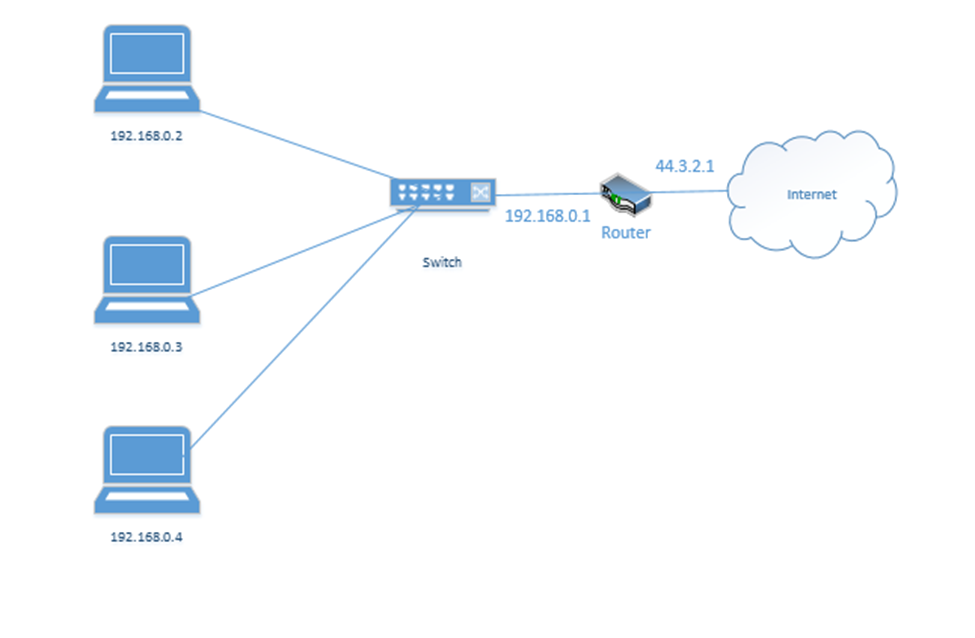
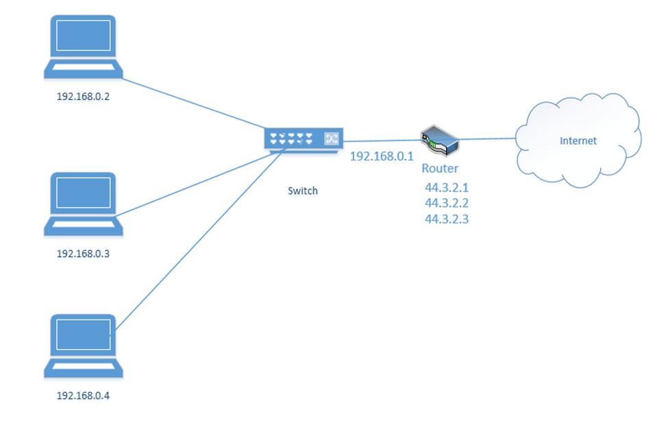
Consider the following example. I have a router with the address 44.3.2.1. That is the address that devices on the internet know it as. Behind the router is my internal network, which has three devices, each with a different address – 192.168.0.1, 192.168.0.2, and 192.168.0.3. Nobody on the internet knows anything about my internal network – they can only see my router.
Remember that addresses that start with 192.168 are known as private IP addresses. They can only be used on internal networks. 44.3.2.1 is an example of a public IP address. But how can a computer on an internal network talk with devices on the internet? And how can devices on the internet talk to a computer on an internal network?
We use a system called Network Address Translation, or NAT. NAT is a tool used by the router to move traffic between the internet and the local network devices. There are several ways that NAT can work depending on the number of public IP addresses available to the router and depending on the number of devices on the internal network.
Let’s say the router has three public IP addresses – 44.3.2.1, 44.3.2.2, and 44.3.2.3 – at least one public IP address for each private IP address. The router has two options for moving traffic between the internet and the internal network
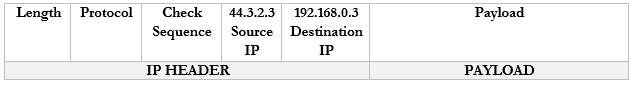
- It can create a Static NAT, also known as a one-to-one translation. The router says that 44.3.2.1 belongs to the device 192.168.0.2; 44.3.2.2 belongs to the device 192.168.0.3 and 44.3.2.3 belongs to the device 192.168.0.4.
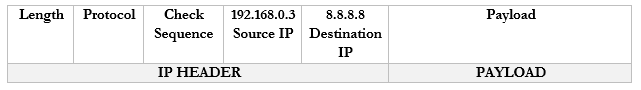
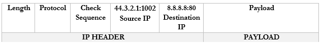
Let’s look at an example. 192.168.0.3 wants to send traffic to google.com (8.8.8.8).- The device creates a packet with a source field of 192.168.0.3, and a destination field of 8.8.8.8
- The device creates a packet with a source field of 192.168.0.3, and a destination field of 8.8.8.8
- The device wraps the packet in an ethernet frame and sends it to the router (the frame’s destination MAC address is that of the router)

- The router strips the frame header and looks at the packet
- The router changes the Source IP (192.168.0.3) of the packet to reflect its external address. It knows that it mapped 44.3.2.3 to the internal IP 192.168.0.3, so that is the IP address that it uses.
- The router changes the Source IP (192.168.0.3) of the packet to reflect its external address. It knows that it mapped 44.3.2.3 to the internal IP 192.168.0.3, so that is the IP address that it uses.
- The router sends the packet to the 8.8.8.8 address. It uses a routing protocol to send this packet, which we will worry about later.
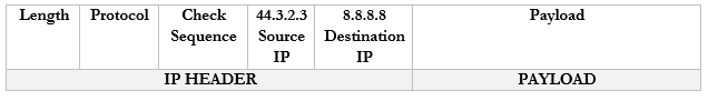
- The Google server at 8.8.8.8 receives the packet and sees that it came from 44.3.2.3
- The Google server replies to 44.3.2.3 by creating a packet with a Destination IP of 44.3.2.3
- The Google server at 8.8.8.8 receives the packet and sees that it came from 44.3.2.3
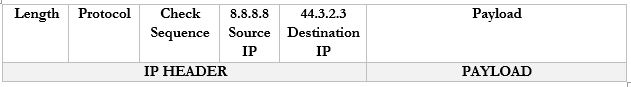
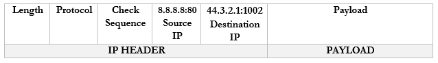
- The router receives this packet and checks the NAT mapping. It knows that 44.3.2.3 is mapped to 192.168.0.3
- It changes the Destination field in the packet to 192.168.0.3 and wraps it in a frame.
- It puts the MAC address of the computer in to field and sends it to the computer through the switch.
- It changes the Destination field in the packet to 192.168.0.3 and wraps it in a frame.
- One-to-one translation is great but remember that IPv4 addresses are scarce. What if I have more internal devices than IP addresses (which is usually the case)? I might need to set up a Dynamic NAT.
Dynamic NAT works exactly like the Static NAT with one difference. That is, with a Dynamic NAT, the router maintains a “pool” of external IP addresses. Each time an internal device needs to access the internet, the router assigns it an external address from the pool. The router keeps track of the assignments in a table. It changes the addresses on the packets just like it did with the Static NAT.
As long as the device is accessing the internet, it continues to be assigned to the external IP address. If a device doesn’t access the internet for a while, then the NAT entry is deleted from the table and the IP address returns to the pool. - But what if I have a massive number of internal devices and they all want to access the internet at the same time? What if I don’t have enough IP addresses to go around even with Dynamic NAT? I can use PAT or Port Address Translation.
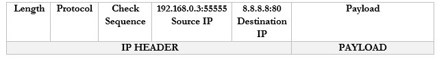
We haven’t talked about “ports” yet. But we are going to introduce a new idea. Look at the computers on the left. Each one has one IP address but it might have many different applications that connect to the internet – e-mail, Skype, Teams, Windows Update, web browser, etc.. If it is receiving traffic from multiple sources, how does it know which source should be directed to each application? Introducing ports. A port is a number that is attached to the end of the IP address. In this case, we aren’t talking about physical ports, but logical ports.
Things are going to get more complicated. The Google server way in California spends its whole day listening to incoming web traffic. It does so on port 80. That is, it understands that traffic sent to 8.8.8.8:80 is requesting the Google website. It might ignore other traffic, or it might listen for different types of traffic on other ports. For example, it might listen for management traffic on port 300.
Now, let’s say that I have 100 browser tabs open at the same time. I am trying to access Google, CNN, YouTube, etc.. If my computer is bombarded with traffic from all these sources at the same time, it will not know which packet goes where. So, what can it do? It adds a port to the end of each request.
For example, it sends a packet to Google.com with the port 55555 as the source. Google.com knows that it should send a reply back to 192.168.0.3:55555.
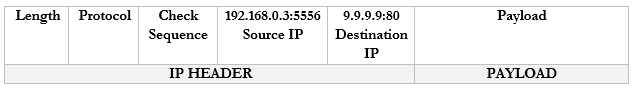
It sends a packet to CNN.com with the port 55556 as the source. CNN.com knows that it should send a reply back to 192.168.0.3:55556.
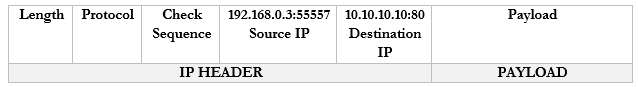
It sends a packet to YouTube.com with the port 55557 as the source. Google.com knows that it should send a reply back to 192.168.0.3:55557.
These port numbers were present in the NAT scheme. But the router didn’t change the port numbers. It didn’t have to because it only changed the IP address (there was a unique address for each internal device). Now there isn’t.
A router doesn’t really have different software applications. But it can still understand ports. Ports allow the router to expand the number of IP addresses.
Let’s look at our example. But now our router has only one external IP address: 44.3.2.1.
- Our computer wants to access Google.com
- It creates the following packet and packages it into an Ethernet frame, which it sends to the router
- It creates the following packet and packages it into an Ethernet frame, which it sends to the router
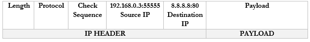
- Our router sees the source and destination. It creates an internal translation between the source IP/port and the external IP. It chooses an available external port, in this case 1002.
- 192.168.0.3:55555 -> 44.3.2.1:1002
- 192.168.0.3:55555 -> 44.3.2.1:1002

- Now our router knows that any traffic received on 44.3.2.1:1002 should be forwarded to the internal address/port 192.168.0.3:55555
- The router changes the Source IP/Port in the packet to reflect the external IP/port and forwards it to 8.8.8.8:80
- The router changes the Source IP/Port in the packet to reflect the external IP/port and forwards it to 8.8.8.8:80
- Google.com receives the packet and sees that it came from 44.3.2.1:1002.
- It creates a packet and replies to 44.3.2.1:1002.
- It creates a packet and replies to 44.3.2.1:1002.
- The router notices that it received a packet on port 44.3.2.1:1002.
- It checks the port mapping table and realizes that this packet belongs to 192.168.0.3:55555
- It changes the destination to 192.168.0.1:80 and forwards the packet. I should say that it wraps the packet inside an ethernet frame (and puts the MAC address of the computer in the destination field).
- It checks the port mapping table and realizes that this packet belongs to 192.168.0.3:55555
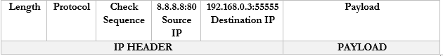
- The computer receives the packet and sees that it arrived on port 55555. Based on its records, it knows that it was listening for traffic from Google.com on port 55555, and it knows what to do with the traffic.
- If the computer decides to seek traffic from another website (with another port), the router will learn about the traffic and create a new mapping. For example
- 192.168.0.3:55556 -> 44.3.2.1:1003
- 192.168.0.3:55557 -> 44.3.2.1:1004
- 192.168.0.3:55556 -> 44.3.2.1:1003
- If the computer decides to seek traffic from another website (with another port), the router will learn about the traffic and create a new mapping. For example
A Content/URL Filter is a simplified version of a firewall that blocks specific websites or types of websites based on their URLs. The filter might also block portions of a website such as the advertisements or videos.
A firewall can be open-source or proprietary, hardware or software based, appliance or host-based or virtual.
- Open Source vs Proprietary. An Open Source firewall is one where the source code is available to the public. That means that we can modify the source code as we wish. We can also verify that the firewall does not have any back doors. Some open source firewalls have a large community that is dedicated to improving the software.
A Proprietary firewall is one where the source code is not available to anybody but the manufacturer. If we use a proprietary firewall, we must trust that its manufacturer did not introduce any security vulnerabilities. - Hardware-Based vs Software-Based. A hardware-based firewall is one that runs on a dedicated piece of equipment. The hardware-based firewall will be customized to the task of filtering traffic. We must purchase a hardware-based firewall that the required capacity for our network. One that is too big might be too expensive. If our network traffic grows, we might need to purchase a more powerful firewall.
A software-based firewall is an application that can be installed on a server or other type of generic hardware. The server will not have hardware that is specifically suitable for filtering traffic but might be adequate. A software-based firewall might be distributed; that is, we might install the software-based firewall on all the devices in our office (computers, servers, etc.) Then each instance of the firewall can filter traffic for the device that it is on. This might be more efficient because as we add additional devices, we just install another copy of the firewall. - Appliance-Based vs Host-Based vs Virtual. An Appliance-Based firewall is one that runs on a dedicated piece of hardware. A Host-Based firewall is one that runs on each user device such as a desktop, laptop, or server. A virtual firewall is one that runs on a virtual machine, within the realm of software defined networking.
Other things we can enforce
- Access Control List (ACL). An ACL is a set of rules for what traffic is permitted to pass and what traffic is not permitted. It may be part of the configuration for a router or firewall.
- Route Security. To understand route security, we must first understand how routers move traffic between one network and another. The internet is a bunch of cables, and different sections are owned by different internet service providers. Thus, your data must pass through many routers controlled by many companies. The internet is a massive spider web. It’s like the highway system. On a long trip, there are many routes you could take and arrive at the same destination. How does the data packet know which route to take? It uses a routing protocol.
In other words- The router receives a packet
- It asks, what is the destination for this packet
- Based on the final destination, where do I send this packet?
- The router receives a packet
There are three types of routes
- Static. A static route is programmed into the router. We tell the router that packets addressed to a specific destination (or range of destinations) take this specific route. We can provide one static route or many.
- Dynamic. The router figures out routes on its own using one of the routing protocols.
- Default. The default route is used when there are no other destinations for the packet. When the router receives a packet, it first checks the static route table. If it can transmit the packet via a static route, it does. If the packet’s destination does not match a static route, then the router sends the packet over a dynamic route. If the packet does not match a dynamic route, then the router sends the packet over the default route.
- Dynamic. The router figures out routes on its own using one of the routing protocols.
When we plug a router in to the internet, it has to learn about the routes by talking to other routers. There are four main dynamic routing protocols: RIP, OSPF, EGRIP, and BGP.
The router doesn’t care about the entire route; it only cares about the address of the next router, or the “next hop”. When a router receives a packet, it asks, “which router should I send this packet to next?” and sends it off. Each router makes its own decision about the next destination without considering the source of the data.
The problem is that most routers trust the data that other routers send it. A malicious person could set up a router that advertises bad routes and bring parts of the internet offline.
For example, if Google is located at 8.8.8.8 and your ISP’s router knows the route to 8.8.8.8, but you somehow connect a router that tells your ISP that Google is located at 9.9.9.9, then your ISP’s router will send all of Google’s traffic to 9.9.9.9, which will just dump it. Now Google is offline, as far as your ISPs customer’s can tell.
If your ISP is connected to a larger regional ISP, it might tell that ISP’s router that Google is located at 9.9.9.9. Now none of the user’s in that region will be able to access Google because their traffic will go to the wrong destination.
It’s not that something happened to Google’s systems. They are still connected and operating the way that they should be, but nobody can reach them.
On October 5, 2021, Facebook and Instagram went offline for about five hours because somebody deleted their BGP routes from their own routers. Since Facebook routers stopped advertising routes into their network, ISP routers stopped sending them traffic, and Facebook appeared offline.
- Quality of Service (QoS) is a concept regarding how well a specific network service is performing. We can measure different things like bandwidth (speed), packet loss (what percentage of data is reaching its destination), jitter (does the data we send show up in the same order or is it all mixed up).
QoS is most important in VoIP and live video applications. Why? Remember that TCP follows a three-way handshake? If I send you a file, you must acknowledge that you received it. If a computer sends a packet to another computer, the recipient must acknowledge receipt. If something happens to the packet along the way, it could always be retransmitted. A small amount of packet loss is a minor annoyance. Maybe the users don’t even notice. If the packets don’t arrive in the correct order, the receiving computer puts them back together.
With VoIP and live video however, imagine that each word you say is a packet. The phone or video screen on the other side must play those packets back to the other party in real time. It doesn’t have time to correct for errors. If some packets go missing, then the person on the phone with you doesn’t hear some of the words you said. If packets arrive in the wrong order, then the words you say are heard in the wrong order on the other side. Too much of that and the users become frustrated.
What are some things we measure when we say Quality of Service?- How much bandwidth are we getting? This is known as throughput, or Goodput. Goodput is the useable bandwidth (actual bandwidth minus overhead for protocols). It’s like the weight of the mail without the envelopes.
- Packet loss. What percentage of packets are lost in transmission?
- Errors. What percentage of packets arrive without errors?
- Latency. How long does a packet take to reach its destination?
- Out-of-Order delivery. Are the packets arriving in the same order that they were sent?
- How much bandwidth are we getting? This is known as throughput, or Goodput. Goodput is the useable bandwidth (actual bandwidth minus overhead for protocols). It’s like the weight of the mail without the envelopes.
A customer and his internet service provider may enter into an agreement to obtain a specific level of service. How can the ISP meet this obligation? Over-provision the network so that it has much more capacity then is required.
But a single service provider doesn’t own the entire internet! Your traffic first reaches your ISP and then it reaches your ISP’s ISP, and then your ISPs ISPs ISP…therefore, the ISPs must negotiate a way to prioritize certain types of traffic so that customers who pay more experience better service.
- Implications of IPv6. When IPv4 was invented, the internet was small, and everything worked well because only big universities and the government could afford to get online. So little thought was given to security in the original design. But people are generally bad, and the bad ones wrecked the internet for everybody else. Eventually, we realized that we were going to run out of IP addresses, so they invented IPv6. When they did, they made security part of the design.
- Port Spanning/Port Mirroring. Port Mirroring is a concept where one port on a switch produces the same traffic as another port. We can set up port mirroring when we want to spy on the traffic received by one port. We can mirror traffic on an entire VLAN, not just a single port, and send it to a monitoring appliance. A switch does not give traffic on a mirrored port much priority.
We can also install a port tap. A tap is a physical device that sits between two network devices. It does not have an IP address or MAC address and it copies all the data transmitted in both directions, which it sends to the monitoring device.
Taps work on copper and fiber and are available in speeds from 10 Mbps to 400 Gbps. - File Integrity Monitors are tools that check critical system files to see if any changes have been made. A change could indicate that an intrusion is in progress.