
3.4 Given a scenario, install and configure wireless security settings
- Cryptographic Protocols
- Wi-Fi Protected Access 2 (WPA2)
- Wi-Fi Protected Access 3 (WPA3)
- Counter-mode / CBC-MAC Protocol (CCMP)
- Simultaneous Authentication of Equals (SAE)
- Authentication Protocols
- Extensible Authentication Protocol (EAP)
- Protected Extensible Authentication Protocol (PEAP)
- EAP-FAST
- EAP-TLS
- EAP-TTLS
- IEEE 802.1X
- Remote Authentication Dial-in User Service (RADIUS) Federation
- Methods
- Pre-Shared Key (PSK) vs Enterprise vs Open
- Wi-Fi Protected Setup (WPS)
- Captive Portals
- Installation Considerations
- Site Surveys
- Heat Maps
- Wi-Fi Analyzers
- Channel Overlaps
- Wireless Access Point (WAP) Placement
- Controller and Access Point Security
Before we can learn about Wi-Fi security, we must learn a bit about how Wi-Fi works. All Wi-Fi protocols are regulated by IEEE (Institute of Electrical and Electronics Engineers). Collectively, we call them 802.11. As the demand for technology increases, new standards are released. The current standard is 802.11ac.
An access point or client (computer, phone, Wi-Fi adapter) may support multiple standards. The standards are backwards compatible (for example, an 802.11ac device will work with an 802.11a device).
Six standards have emerged
| 802.11a | 1999 Standard Supports up to 54 Mbps in the 5GHz range |
| 802.11b | 1999 Standard Supports up to 11 Mbps in the 2.4GHz range |
| 802.11g | 2003 Standard Up to 54 Mbps in the 2.4GHz range If all the devices on a network are at the 802.11g level, then the network operates at 54 Mbps. Otherwise, it operates at 11 Mbps to support the older devices. |
| 802.11n (Wi-Fi 4) | 2009 Standard Supports multiple-input, multiple-output (MIMO) – an access point device with multiple antennas Up to 72.2 Mbps with one send and one receive antenna Up to 450 Mbps with three send and three receive antennas Also supports transmit beamforming which focuses the signal so that there are no dead zones It has a better way of supporting older devices. It can operate in one of three modes Legacy means it sends separate packets for older devices, which is not efficient Mixed means it sends out standard packets that support older devices and newer devices. We might also call this high-throughput or 802.11a-ht or 802.11g-ht. Greenfield means that it sends out 802.11n packets that support newer devices, but not older devices |
| 802.11ac (Wi-Fi 5) | 2014 Standard Supports multiuser multiple-input, multiple-output (MIMO) Up to 433 Mbps per antenna, or 1.3Gbps with three antennas |
| 802.11ax (Wi-Fi 6) | 2021 standard In addition to all the features of Wi-Fi 5, Wi-Fi 6 offers a 400% improvement in throughput and a 75% drop in latency. It has the best performance in high-density areas such as offices. It takes advantage of cellular technology called orthogonal frequency-division multiple access, which optimizes the radio signal. While the previous Wi-Fi standards operated in the 2.4Ghz and 5Ghz bands, Wi-Fi 6 also operates at 6Ghz (technically 5.925Ghz to 7.125Ghz). |
The standard provides guidelines that manufacturers of wireless devices use when making devices. With a reliable standard, products from different manufacturers all work together. Just think about it – it doesn’t really matter what brand laptop or phone you have, it generally works with the Wi-Fi at your office, your home, the airport, the mall, your friend’s house, etc. That’s because the Wi-Fi card in your device follows the same standard as the Wireless Access Points installed everywhere.
Which Wi-Fi device should you select? Obviously, the latest version is the best! Technology will continue to improve, and you don’t want to be stuck with something that is obsolete by the time you install it.
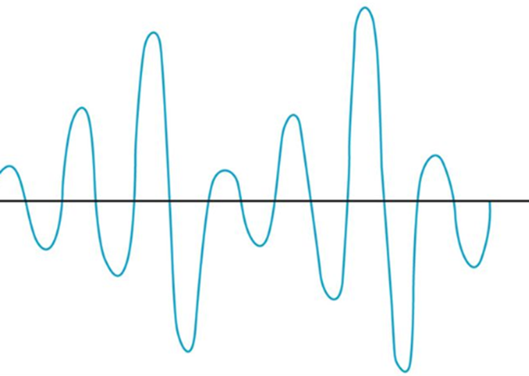
A radio signal (like the one used in Wi-Fi and cell towers) is like a wave. It goes up and down.

The height of the wave is called the Amplitude. The width of the wave is called the wave length. No matter the height or the width, the wave travels at the speed of light. You can think of a Wi-Fi signal like light that you can’t see, because scientifically, that’s exactly what it is. Thus, the wider the wave (the larger the wavelength), the less waves will pass through each second. We call this the frequency, measured as the number of waves that pass through per second. We measure frequency in Hertz (Hz).
If you had special glasses that would let you see waves in the air, it would look like a big mess of waves travelling everywhere. So, each device is programmed to “look” for waves at a specific frequency and ignore the rest.
The government regulates the frequency that each type of technology can use. If everybody could broadcast signals at any frequency they wanted, the air would be a mess and wireless systems would not be able to function.
Wi-Fi signals travel at a frequency of 2.4GHz and 5GHz (and 6Ghz soon). Older cordless phones use a signal with a frequency of 900MHz.
If we change the Amplitude of the wave over time (up and down), we can use it to convey information.
The range of a Wi-Fi signal is between 50 and 300 feet. It is affected by signal interference (noise) from neighboring networks. Different wall types can block or reduce the signal (glass, concrete, steel will block signals more than drywall).
The 2.4GHz range has eleven channels. It has a longer range and is less vulnerable to noise than the 5GHz range, which has twenty-three channels. Older devices use the 2.4GHz range. What’s a channel?
When two waves with the same frequency collide, they cancel each other out and the signal is lost. If I have a Wi-Fi network and my neighbor has a Wi-Fi network, the signals will interfere, and nobody will be able to understand anything. To solve this problem, we divide the 2.4GHz spectrum into 11 channels: Each channel is 22MHz wide, spaced 5MHz apart.
Therefore, a 2.4GHz network is not actually broadcasting at a frequency of exactly 2.4000000GHz, but instead at 2.412GHz, 2.417GHz, or 2.422GHz, etc.
If two neighboring networks choose different channels, they will each broadcast on a slightly different frequency – different enough that their signals won’t interfere. We can manually select the channel that we want to broadcast on, or we can let our wireless system choose it for us. We should survey the neighboring networks to see what channels they are broadcasting on and select a different channel from all of them. If we have multiple access points in a building and their signals overlap, we should select a different channel for each of them.
The channel concept applies to 5GHz networks as well. A 5GHz spectrum is divided into 23 channels, each is 20MHz wide. A 5GHz spectrum can broadcast on 5.150GHz, 5.1570GHz, etc. There are more regulations for the 5GHz network and some countries do not allow some frequencies (they could interfere with weather radar and other systems).
If our network does not have enough bandwidth, we can bond two adjacent channels together to double its capacity. This is known as channel bonding. We combine two 20MHz channels into one 40MHz channel. One of the channels is the primary channel, and the other is secondary. Client devices that use channel bonding will transmit and receive on both channels, while client devices that don’t support it will only use the primary channel.
5GHz has one complication. Some of the frequencies in the 5GHz range are also used by government weather radar systems. If your device is using a frequency in the range of a government radar system, it must first scan to see if such a device is present. If it is, your device must switch to a different channel for at least an hour and then scan again. That is, the government devices get first dibs on some of the 5GHz channels and don’t allow interference from consumer devices. Devices have a feature called dynamic frequency selection (DFS), which allows them to detect the nearby signal and switch over.
- Channels in the range of 5.150Ghz to 5.250Ghz are always permitted
- Channels in the range of 5.170Ghz to 5.740Ghz are only permitted when not in use by a government device. A device using this range must have dynamic frequency selection so that it can switch to another channel once it detects a government device.
- Channels in the range of 5.735Ghz to 5.815Ghz are always permitted.
- Channels in the range of 5.815 to 5.895 are permitted for indoor use only
High end devices such as smartphones and wireless access points will use dynamic frequency selection. Cheaper devices will not. If a wireless access point switches to a DFS channel, cheaper devices will not be able to detect the signal and will switch to the 2.4Ghz range instead.
Every country regulates the use of wireless signals and some channels that are available for use in the United States are not available in other countries. When you set up a wireless device, you must check the regulations in your country and verify that you are broadcasting in a range that is permitted. Regulations are subject to change and a channel that was legal before may become illegal later.
There are two general types of networks
- An ad hoc network is when two devices try to connect to each other directly. For example, when you connect to a wireless printer, you are using an ad hoc network.
- An infrastructure network is one with wireless access points. Devices, known as clients, connect to the network through the wireless access points
The SSID is or Service Set Identifier is the name of the network. An SSID is mapped to a WLAN (Wireless Local Area Network), and a WLAN is typically mapped to a VLAN (Virtual Local Area Network). Multiple SSIDs/WLANs can be mapped to the same VLAN. The purpose of an SSID is to allow us to separate wireless traffic the same way that we can separate wired traffic.
A single wireless access point can broadcast multiple SSIDs. For example, we might have a “Guest” SSID for guests, a “Staff” SSID for staff, and an “IoT” SSID for smart devices. If we have a large office with multiple wireless access points, each wireless access point can be configured to broadcast all the SSIDs.
If I have a large office, one wireless access point won’t be able to provide a good signal across the entire floor. I might place my access points like this and give each of them a different channel (or the controller might assign each one a different channel automatically). Each access point has its own MAC address, but all are broadcasting the same SSIDs.
What happens when I connect to the “Staff” SSID and I’m standing at the top left corner of the office? My laptop will probably connect to the closest access point (because it has the strongest signal). It might see “Staff” SSIDs from other access points nearby with weaker signals and different channels. As I move throughout the office, the signal from the first access point I connected to will become weaker, but my laptop will automatically move its connection to another wireless access point that is broadcasting the “Staff” SSID. This process is called roaming. When multiple access points create a seamless SSID, it is known as an ESSID or Extended Service Set Identifier.
The BSSID or Basic Service Set Identifier is the name (or MAC address) of the physical access point that I am connected to. Thus, within a given SSID, there can be one or multiple BSSIDs. If an access point is broadcasting multiple SSIDs, then that access point will also have multiple BSSIDs. That is, an access point will have multiple MAC addresses assigned to it by the manufacturer – one physical MAC address that it uses to communicate with the wired network, and multiple wireless MAC addresses that it can assign to each SSID. The number of SSIDs that a wireless access point can broadcast is limited to the number of wireless MAC addresses that are assigned to it.
The portion of the access point that broadcasts the signal is called the radio. An access point can have multiple radios. Having multiple radios allows the access point to communicate with multiple devices at the same time. An access point will need a unique MAC address for each radio-SSID combination. Thus, if an access point can broadcast 32 SSIDs and has two radios, it will have 64 wireless MAC addresses.
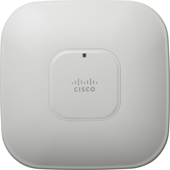
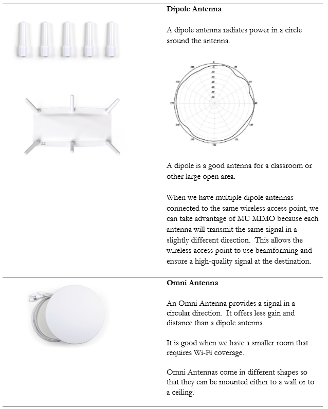
Below is a common Wireless Access Point, the Cisco Aironet 1142N. This access point has antennas concealed inside it. It’s considered omnidirectional, because it broadcasts in all directions. Most access points are omnidirectional. We can mount it to a ceiling and it will provide good coverage in an office.
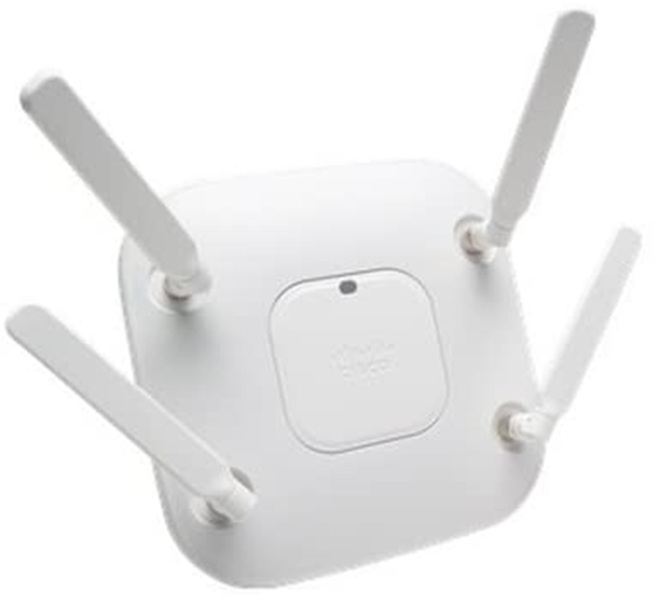
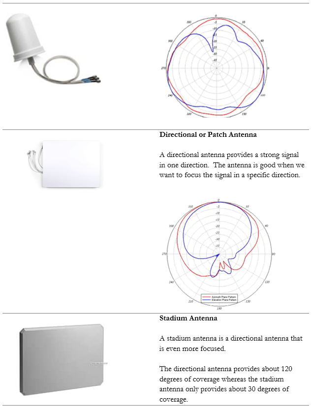
What if I have a problem where I need to point a Wi-Fi signal in a specific direction? I could attach external antennas to the access point and mount them facing the direction that I require. This is known as unidirectional transmission. Antennas are available in different shapes and sizes. Antennas also increase the signal strength of the access point.
An example of an access point with antennas is below
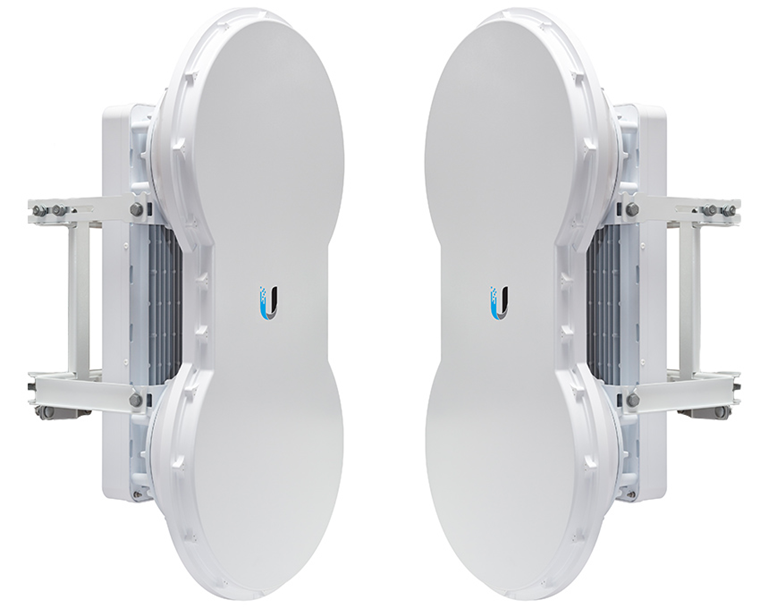
Another example of powerful directional antennas is the Ubiquiti AirFiber. It allows us to send a strong Wi-Fi signal long distances by pointing it in a specific direction. For example, I could use the AirFiber to connect two far away buildings via a wireless connection.
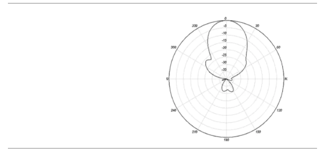
There are many other types of antennas, each of which has a different pattern and purpose.
How do we secure the communication between the wireless access point and the wireless device? How do we ensure that unauthorized users can’t connect? There are several forms of wireless encryption.
- WEP (Wired Equivalent Privacy) encryption uses a password to authenticate the host with the access point.
- An administrator configures a password on the wireless access point
- The authorized users are provided with the password, which they use to authenticate with the access point
- All further communications are encrypted with the provided password
- A packet sniffer can intercept packets and easily crack the password.
- WEP has been known to be insecure since 2005 but is still in use today.
- WPA keys were 64-bits long.
- WEP is not recommended
- An administrator configures a password on the wireless access point
- WPA (Wi-Fi Protected Access) and WPA2 use a password to create a handshake (which creates a unique one-time password) between the host and the access point.
- An administrator must create a WPA or WPA2 password and configure it on each access point
- The authorized users are provided with the password, which they use to authenticate with the access point
- When a device first connects to a wireless access point, the device and the WAP follow a handshake process to create a unique one-time key that the two parties use to encrypt all further communications
- WPA is more secure than WEP because the key is much longer and because every connection is encrypted with a different password
- A packet sniffer can intercept packets during the handshake process and identify the password.
- WPA uses 256-bit keys
- WPA2 uses AES encryption algorithms and has replaced WPA
- The process for a client connecting to a WAP is called Counter Mode Cipher Block Chaining Message Authentication Code Protocol (Counter Mode CBC-MAC Protocol)
- There was a Pre-Shared Key (PSK), also known as the Wi-Fi password. The WAP converts it into a 256-bit Pairwise Master Key (PMK)
- The WAP sends the client a random number called the ANONCE
- The client uses the ANONCE to generate a Pairwise Transit Key (PTK). It combines it with the PMK, the SNONCE (random number that the client has generated), and the MAC addresses of itself and the WAP
- PTK = PMK + ANONCE + SNONCE + MAC (WAP) + MAC (CLIENT)
- The client sends the SNONCE to the WAP
- The WAP generates a Group Temporal Key (GTK)
- Thus, the WAP and the client are agreeing on a new key for each connection. If a hacker intercepts the handshake messages, he can insert one of his own keys into the handshake.
A hacker could also intercept some Wi-Fi data and use an offline-dictionary attack to crack the PSK. In WPA2 Personal, an attacker (or other user) with the PSK could intercept and spy on the traffic between the WAP and other clients.
- There was a Pre-Shared Key (PSK), also known as the Wi-Fi password. The WAP converts it into a 256-bit Pairwise Master Key (PMK)
- An administrator must create a WPA or WPA2 password and configure it on each access point
- WPA Enterprise uses a RADIUS server to authenticate the identity of the host attempting to connect. The host will typically present a digitally signed certificate to the RADIUS server (i.e. the host computer must have a certificate installed to connect to the network). Another option is for the host to sign in to the wireless network by entering a username and password. Certificate-based WPA Enterprise is difficult to break, provided that the certificates are digitally signed using a strong algorithm and that there are no other flaws in the access point or RADIUS server. Username/password based WPA Enterprise can be broken if the username/password are intercepted. An attacker could set up a rogue access point broadcasting the same SSID and then intercept usernames/passwords.
- WPA3 was released in 2018 but has not been widely adopted yet. It uses a 192-bit key. Instead of having a pre-shared key, we use Simultaneous Authentication of Equals.
With Simultaneous Authentication of Equals (also known as a dragonfly), it is more difficult for the hacker to intercept the handshake. It is based on a Diffie-Hellman Key Exchange with elliptic curve cryptography.
- Client and WAP choose a prime number and a curve
- Client and WAP choose a hash function
- Client and WAP choose a shared password
- Client and WAP each calculate from by checking for a valid point on the curve
- Client chooses a random integer in the curve domain and calculates , and sends it to WAP
- WAP chooses a random integer in the curve domain and calculates , and sends it to WAP
- Client calculates the key from and WAP calculates the key from
- That means that the client and the WAP each calculated their key independently
- An offline dictionary attack does not work because we would need to find K and even if we guessed G, we could not guess and
- Client and WAP choose a hash function
Some people say that SAE (dragonfly) is not secure. It hasn’t been around very long, so if there is a security hole (and there might be!), people just don’t know about it yet.
- TKIP (Temporal Key Integrity Protocol) was a standard that was introduced to temporarily replace WEP.
- WEP had been broken and the Wi-Fi alliance needed a quick solution to replace it without forcing customers to replace physical hardware
- TKIP is no longer considered secure
- TKIP uses the same functions as WEP, except that it
- Adds an initialization vector to the secret key
- Uses a sequence counter to prevent replay attacks
- Uses a 64-bit Message Integrity Check
- Encrypts every data packet with a unique encryption key
- Adds an initialization vector to the secret key
- WEP had been broken and the Wi-Fi alliance needed a quick solution to replace it without forcing customers to replace physical hardware
- WPS or Wireless Protected Setup, was a feature that allowed devices to connect to a wireless network without having to enter a security key. It was designed for cheaper devices such as printers (that often didn’t have a keypad/touchscreen interface to enter the key). A user could connect their printer to the network by pressing the “WPS” button on their access point and then waiting for it to pair with their wireless device.
- WPS exchanges an 8-digit code with the wireless device, which can be easily detected through brute force. The eighth digit of the code is a checksum, and the first four digits are evaluated separately from the next three. WPS therefore requires a maximum of 11,000 attempts to brute force it.
- WPS is available on residential-grade equipment
- WPS exchanges an 8-digit code with the wireless device, which can be easily detected through brute force. The eighth digit of the code is a checksum, and the first four digits are evaluated separately from the next three. WPS therefore requires a maximum of 11,000 attempts to brute force it.
- Captive Portals. A Captive Portal is a website that shows up when an unauthorized user connects to a Wi-Fi network
- Typically, a captive portal is installed on an open “guest’ network such as at a hotel, airport, shopping mall, or library
- The user is required to authenticate using a username/password or just a password
- The captive portal may require the user to pay to access the internet (or to access the internet at a faster speed)
- The user will need to agree to an Acceptable Use Policy agreement; the vendor may be able to monitor the type and amount of traffic generated by the user
- The captive portal is a web page that would be hosted on an internal server or firewall.
- Essentially, http (port 80) and https (port 445) traffic is redirected to the captive portal. The firewall may also redirect all DNS traffic to send the user to the captive portal page.
- While the user is unauthenticated, the firewall should be configured to block any traffic outside of port 80 and port 445, and block any traffic external to the captive portal.
- If external traffic/ports are open, the user could circumvent the captive portal by establishing a VPN tunnel
- Typically, a captive portal is installed on an open “guest’ network such as at a hotel, airport, shopping mall, or library
- Open. An open network is one that does not have any password. Anybody can connect. This is a bad idea, even for a guest network.
WPA, WPA2, WPA3, etc. provide encryption between the WAP and the client. But how does the WAP know that the client is authorized to connect? There are many authentication protocols for wireless technology
- EAP (Extensible Authentication Protocol)
- EAP is a framework for providing authentication, but there are more than 40 possible methods that can be used
- RFC 5247.has defined EAP
- Each vendor may have more specific requirements and new protocols are being developed all the time
- EAP is a framework for providing authentication, but there are more than 40 possible methods that can be used
- LEAP (Lightweight Extensible Authentication Protocol)
- Developed by Cisco
- LEAP is not supported by Windows but is supported by many third-party applications
- Cisco does not recommend using LEAP anymore because it does not protect user credentials
- Developed by Cisco
- PEAP (Protected Extensible Authentication Protocol)
- Originally, EAP assumed that communications would be secure; therefore, it did not provide a mechanism to secure the data being transmitted.
- PEAP corrects this by providing a secure TLS tunnel
- A server-side certificate is used to create a PKI tunnel
- Originally, EAP assumed that communications would be secure; therefore, it did not provide a mechanism to secure the data being transmitted.
- EAP-NOOB (Nimble out-of-band authentication for EAP)
- Used by devices that do not have preloaded authentication information such as Internet of Things devices
- The user must assist the device in connecting via an out of band channel
- There are different connection options including QR codes and NFC
- Ephemeral Elliptic Curve Diffie-Hellman (ECDHE) exchange takes place over the in-band EAP channel. The user then provides the out-of-band channel message from the server to the device or from the device to the server, depending on what is required.
- Used by devices that do not have preloaded authentication information such as Internet of Things devices
- EAP-FAST (Flexible Authentication via Secure Tunneling)
- Designed by Cisco to replace LEAP
- It has three parts
- In band provisioning via Diffie-Hellman. The client is provided with a shared secret.
- Tunnel establishment. A tunnel is established between the server and the client.
- Authentication. The user is authenticated
- In band provisioning via Diffie-Hellman. The client is provided with a shared secret.
- Designed by Cisco to replace LEAP
- EAP-TLS (EAP – Transport Layer Security)
- Uses TLS (Transport Layer Security) as its protocol.
- All wireless manufacturers support EAP-TLS
- Considered very secure
- EAP-TLS requires a client-side certificate. When a system is authenticated with a certificate, a password is not required. Even if a hacker obtained the username/password, without a certificate, the hacker would not be able to connect to the Wi-Fi.
- EAP is not implemented as widely as it should be because it requires the certificate
- Uses TLS (Transport Layer Security) as its protocol.
- EAP-TTLS (EAP Tunneled Transport Layer Security)
- Extends TLS so that the client does not require a certificate. Instead, the server creates a tunnel with the client. The client can then authenticate to the server using a legacy password or other authentication method. The tunnel protects the client from eavesdropping.
- Extends TLS so that the client does not require a certificate. Instead, the server creates a tunnel with the client. The client can then authenticate to the server using a legacy password or other authentication method. The tunnel protects the client from eavesdropping.
- IEEE 802.1X
- IEEE 802.1X is a standard for Network Access Control. It allows a device to authenticate when connecting to a LAN or WAN.
- There are three devices
- The supplicant is the device that chooses to connect to the LAN/WAN. It could be a laptop, desktop, smartphone, tablet, or other computing device
- The authenticator is a network device that allows/denies access. It could be a switch, a router, a firewall, or a proxy server.
- The authentication server is a server that decides whether a particular device should be granted access
- The supplicant is the device that chooses to connect to the LAN/WAN. It could be a laptop, desktop, smartphone, tablet, or other computing device
- The procedure
- The supplicant connects to the network
- The authenticator (switch) detects the new supplicant and automatically sets the port to an unauthenticated state. Only traffic related to 802.1X is permitted.
- The authenticator sends frames to the supplicant. These frames demand that the supplicant provide credentials such as a user ID. The frames are sent on the local network segment to a specific address (01:80:C2:00:00:03). The supplicant listens for messages on this address.
- The supplicant replies to the message with an EAP-Response Identity frame
- The authenticator sends the supplicant’s response to an authentication server
- The authentication server and the supplicant negotiate an authentication method. The server and the supplicant may support different methods and must agree on one. The negotiation methods are transported through the authenticator.
- The authentication server attempts to authenticate the suppliant. If successful, the authenticator changes the port status to authorized. If unsuccessful, the authenticator keeps the port as unauthorized.
- When the supplicant logs off or is disconnected, the authenticator changes the port status back to unauthorized. When the supplicant logs off, it sends an EAPOL-Logoff message to the authenticator.
- The supplicant connects to the network
- Security Risks
- A hacker can physically insert himself between the port and the authenticated computer, and then use the authenticated port
- A DDOS attack can take place. A hacker can create EAPOL-logoff messages with the MAC address of the supplicant and send them to the authenticator, forcing the port to go into an unauthorized state. This would force the supplicant to go offline.
- A hacker can physically insert himself between the port and the authenticated computer, and then use the authenticated port
- IEEE 802.1X is a standard for Network Access Control. It allows a device to authenticate when connecting to a LAN or WAN.
- RADIUS Federation
- RADIUS provides network access
- A user requests access from a Network Access Server. The request may contain a username, password, and/or certificate
- The Network Access Server requests access from the RADIUS server
- The RADIUS server verifies the user’s identity. This could come from a database file stored locally, or from a connection to another service such as LDAP, Active Directory, or Kerberos
- The RADIUS server can issue one of three responses
- Access Deny
- Access Accept. The RADIUS server performs further checks to ensure that the user is provided access to only the services that he is entitled to. RADIUS allows an administrator to provide granular access control.
- Access Challenge. The RADIUS server requests additional information from the user, such as a PIN or smart card. The user and the RADIUS server may establish a secure tunnel to exchange the additional authentication data, in a way that shields it from the Network Access Server.
- Access Deny
- When access is granted, a “Start” record is created. The Network Access Server sends a “start” command to the RADIUS server, which indicates that the user can begin access. When access is terminated, a “Stop” command is sent.
- Roaming
- A RADIUS user can roam on multiple networks with the same RADIUS credentials
- Each network is known as a realm (like a domain)
- Each user is assigned to a specific realm (the realm may be appended to the username)
- If a user attempts to connect to a network outside his realm
- The user connects to the RADIUS server and provides his username and realm
- The RADIUS server checks to see if it is configured to accept users from that realm
- The RADIUS server sends the request to the RADIUS server belonging to the user’s realm via a proxy. RADIUS servers should be configured to connect via a secure tunnel, because the default MD5 encryption of user credentials is weak.
- The user connects to the RADIUS server and provides his username and realm
- A RADIUS user can roam on multiple networks with the same RADIUS credentials
- Source Code
- RADIUS is open source
- A specific vendor can implement a customized version of RADIUS, which may contain Vendor Specific Attributes
- RADIUS is open source
- RADIUS provides network access
Remember that Wi-Fi is considered a “one-to-many” connection. One antenna talks to many devices. But as I said before, a wireless access point can only communicate with one device at a time.
Access points use Time Division Multiplexing. The access point sends data to one device, pauses, sends data to the next device, pauses, sends data to the third device, pauses, etc. until it has sent data to all the devices. It is also receiving data from each device in the same pattern.
To send data to multiple devices at the same time, an access point must have multiple antennas and engage in advanced signal processing. This technology is known as Multiple Input, Multiple Output (MIMO).
How does it work?
- Remember that if we send multiple radio signals at the same time, they can either merge and become more powerful, or they can cancel each other out. Whether they merge or cancel each other out depends on the way that they are sent.
- Beamforming is an idea that we can send out signals from multiple antennas in a way that they can all combine at the receiver as a more powerful signal. The receiver uses an algorithm to amplify amplifies the different signals by giving each one a different weight.
- There are three ways
- Precoding – the access point sends out the same signal through multiple antennas. Each signal is given a different phase and weight so that the signals combine at the receiver to have the maximum power.
- Spatial Multiplexing – the access point splits a high-bandwidth signal into multiple low-bandwidth signals. Each signal is transmitted from a different antenna. Spatial multiplexing is good when there is a high level of noise. The receiver splits the signals into channels and interprets the data.
- Diversity Coding – the access point sends the same signal through multiple antennas, but each signal is sent orthogonal to the other ones (at right angles). That means, regardless of how the receiver is facing, it will receive at least one signal correctly.
- Precoding – the access point sends out the same signal through multiple antennas. Each signal is given a different phase and weight so that the signals combine at the receiver to have the maximum power.
We can take this a step further and use a Multi-User MIMO (MU-MIMO). What happens when we want to use MIMO with multiple users at the same time? The access point can divide the signals spatially so that it can serve multiple users at the same time, provided they are some distance apart. When multiple users close together, the signals cannot be separated easily, and those users must share the bandwidth.
Wi-Fi 6 allows MU-MIMO to function in both directions. Previous versions allowed multiple users to be served quickly when downloading, but Wi-Fi 6 allows multiple users to upload data at the same time.
When selecting wireless devices, consider the following
- Purchase wireless access points that support Wi-Fi 6 and MU-MIMO
- As the use of Wi-Fi increases, consider purchasing wireless access points that support a 2.5 Gbit/s or 5 Gbit/s ethernet connection.
- Determine the range of each access point and the area that you must cover; this will allow you to calculate the number of access points required
- Determine the number of devices or users that need to be served and the maximum capacity of the wireless access point
- Consider whether the area that requires coverage has a basic layout or whether specific directional antennas are required
Older Wi-Fi access point typically sends signals (radio waves) in all directions, in the hope that some of them will land on devices that need to connect. Newer Wi-Fi access points use a technique called beam forming to make sure that they get to where they need to go.
What happens to these signals? Some of them hit reflective surfaces. A reflection means that the signal bounces back. Surfaces that cause reflection include metal and glass. A device may pick up a reflected signal, but the range of the signal will be reduced when reflection is involved.
Refraction is when a signal passes through a surface but bends. Surfaces that cause refraction include walls and doors. A device may be able to pick up a refracted signal.
Absorption is when the signal is absorbed by a surface. The signal simply disappears. Very few signals completely consume Wi-Fi signals, but most surfaces absorb a portion of the Wi-Fi signal. An absorbed signal becomes weaker.
We can improve the signal strength by installing antennas. If we install an antenna, we could improve the access point so that the signal strength is -10 dBm at the access point, -40 dBm about 100 ft away, and -70 dBm about 200 ft away.
Remember that there are different types of antennas. A wireless access point will come with a built-in internal antenna, but we might need to add some external ones to improve the signal. Each type provides a signal of a different shape. If we choose the wrong antenna, we will not have the correct coverage. Even if we choose the correct type of antenna, if we point it in the wrong direction, then we won’t have the correct coverage.
For example, if we have a warehouse with tall metal shelves and long aisles, putting access points in the ceiling won’t give us a good signal. Instead, we should install antennas at the end of each aisle and point them down the aisle.
In office buildings, schools, and hospitals, we should avoid putting access points in the hallways. Instead, we should put them inside the classrooms and large open areas where the signal can spread out. If we put an access point in a hallway, the signal will tend to bounce down the wall left to right until it runs out of power.
In a wireless network, latency and jitter can be caused by poor quality access points. If the access point takes a long time to process or transmit the signal, significant latency can develop.
When the access points form a mesh network, a signal may need to travel between several access points to get from the main network to the user’s device. This also increases latency.
We also have latency due to the WAPs advertising themselves (letting users know about their SSIDs). The actual data transmission rate is called throughput. The actual beneficial throughput from an access point is called goodput.
Another item we can measure is RSSI or Received Signal Strength Indication. The RSSI value tells us how strong the wireless signal is at the device that is receiving it. Each manufacturer will use a different scale for the RSSI measurement, so we must check the score against the device’s operating manual to be able to interpret the results.
Effective Isotropic Radiated Power measures the actual power transmitted by an antenna. Consider the following. On the left, I have a Cisco wireless access point, which has four connectors for antennas. On the right, I have a Cisco directional antenna, with four antenna cables.
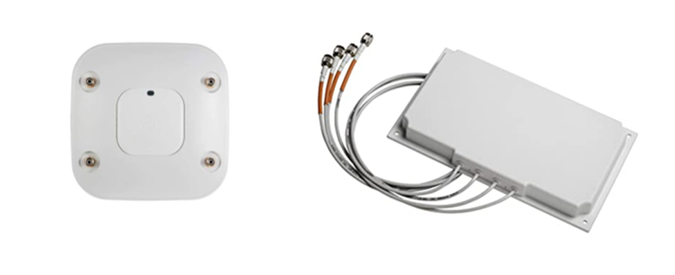
The actual radio signal generated by the wireless access point leaves those four holes, travels down the antenna cables, and is outputted by the directional antenna. If we didn’t have an antenna, the signal from the access point’s transmitter would spread across a large area and would be low. The antenna takes the signal and allows us to focus it in a specific direction.
If the access point has 10 Watts of power, and the antenna has a gain factor of 3 (it multiplies the signal by 3), then the antenna has an effective power of 30 Watts in a specific direction. That is not to say that the system has multiplied the power, since it is impossible for an antenna to create energy. Instead, what we are saying is that the antennas is focusing the power in a specific direction such that a transmitter would have required 30 Watts to accomplish the same task by itself.
It should also be noted that we will lose some power through the antenna cables. The longer the antenna cables, the greater the loss.
Let’s look at some antenna types
When choosing an antenna, decide
- Does the wireless access point have adequate built-in antenna coverage, or do I need an external antenna?
- If I need an external antenna, what type do I need. In other words, where do I need to focus the signal?
- How much gain do I need? Different antennas have different gains.
- How will I mount the antenna?
- Make sure that the antenna supports both 2.4 GHz and 5 GHz. An antenna may have different patterns/gains for each frequency or may only support one frequency.
You must also consider how the antenna is polarized. The polarization is the direction that the signal leaves the antenna. If we have a directional antenna and we don’t know the polarization, then we won’t know how to mount it correctly. The signal may leave the antenna at a completely wrong angle.
We should make sure that all the antennas in our system have the same polarization. Most antennas have a linear (flat) polarization that is oriented horizontally or vertically.
Attenuation is when the signal strength is reduced. The further we get from an access point, the weaker the signal. The signal strength is also reduced by surfaces that reflect, refract, or absorb the signal.
For example, if the signal strength is -40 dBm (a good strength) at the access point, it might be -70 dBm (an average strength) about 100 ft away, and -100 dBm (a weak strength) about 200 ft away.
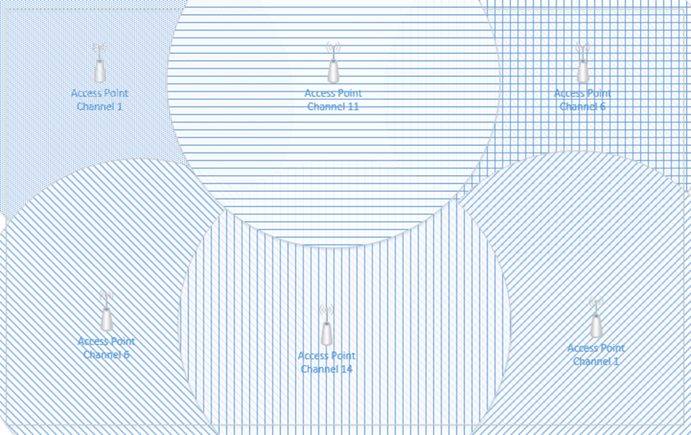
Interference is when two Wi-Fi signals cancel each other out. Consider the following access points, both of which are broadcasting on Channel #1. The signal is good, except where it overlaps, where it cancels out.
A device in the red area will see a weak signal because the access point signals are cancelling each other out. The solution is to change the channel on one of the access points.
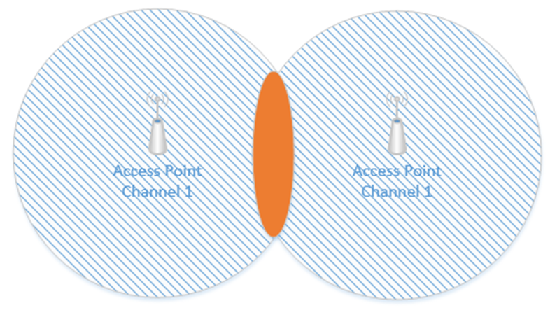
Remember how I said that a Wi-Fi channel is 22 MHz wide and that the channels are spaced 5 MHz apart? That means that on the 2.4 GHz range, the first channel is 2.412 GHz, but it actually ranges from 2.401 GHz to 2.423 GHz. The second channel is 2.417 GHz, but it actually ranges from 2.406 GHz to 2.428 GHz. That means that channels one and two overlap. Thus, we should pick two channels that are far enough apart so that interference does not take place. The sixth channel ranges from 2.426 GHz to 2.448 GHz. In the above example, I should set one access point to Channel 1 and the other access point to Channel 6. Now the signals won’t interfere.
There are two other things we need to consider. An access point may only be able to handle fifty connections – this is an estimate for a high-quality access point; a poor-quality access point may only be able to handle twenty. If I have a conference room or theater with 200 or 400 occupants, even if the access point provides a good signal across the entire room, it may not have the capacity to connect to all the devices. We should install multiple access points to ensure that we have enough capacity. We should spread them out and give each one a different channel. We should also reduce the transmit power on each access point so that it only covers a small portion of the room.
We should install access points to ensure that the signal is at least -67 dBm everywhere. In the past, we used to aim for a -70 dBm signal strength, but as more advanced applications such as streaming video emerged, the requirements grew to -67 dBm.
We should also verify that our Signal to Noise Ratio (SNR) is at least 24. Noise is caused by wireless signals that are outside of our network. Devices such as cell phones, cordless phones, microwaves can cause noise. Other wireless networks can also cause noise. If our SNR ratio is too low, we might need to add additional access points, move the existing access points, install shielding in the building, or remove the sources of noise.
On the 2.4 GHz network, only four channels don’t overlap – 1, 5, 11, and 14. Where possible, we should limit our design to these four channels.
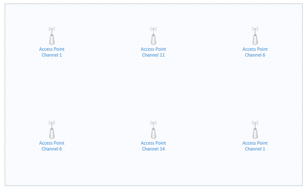
Consider this small rectangular room, which requires six access points due to accommodating many users.

If I space out the access points evenly and set them as best as I can so that there are no neighboring channels, they might look like this.
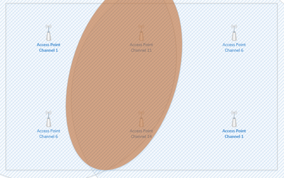
The access points that are on Channel one are in the top left corner and bottom right corner. If we highlight the coverage area of just those two access points, we can see that there is a significant overlap in the middle of the room (shown in red). The red area will have poor coverage due to interference – there will be signals from two access points on Channel one. What can we do?
We can reduce the transmit power of each access point, so that the signal range is weaker. This way, the signals don’t overlap, but we can still cover the entire room with an adequate Wi-Fi signal.

I still have overlapping signals. But the overlap doesn’t extend across the entire room. The access points that overlap are broadcasting on slightly different frequencies; therefore, their signals do not interfere.
Before we install a wireless network, we should first complete a wireless site survey. The site survey allows us to identify the following
- The areas that require wireless coverage
- The type of material that the walls are made of
- The shape and size of the room and buildings
- Any other factors that would affect Wi-Fi coverage
- How the wireless access points will be mounted
- The type of antennas required
- The type of ethernet cabling present; if no ethernet cabling is present than we can determine the best way to install new ethernet cabling
- The distance from the wireless access points to the IDF or MDF
- Whether the existing network equipment will support the addition of new wireless access points. In other words, are there available Gigabit (or 2.5 Gigabit) PoE switch ports?
At the end of the survey, we should have a plan for exactly how we are going to install the new Wi-Fi network, and where they will go.
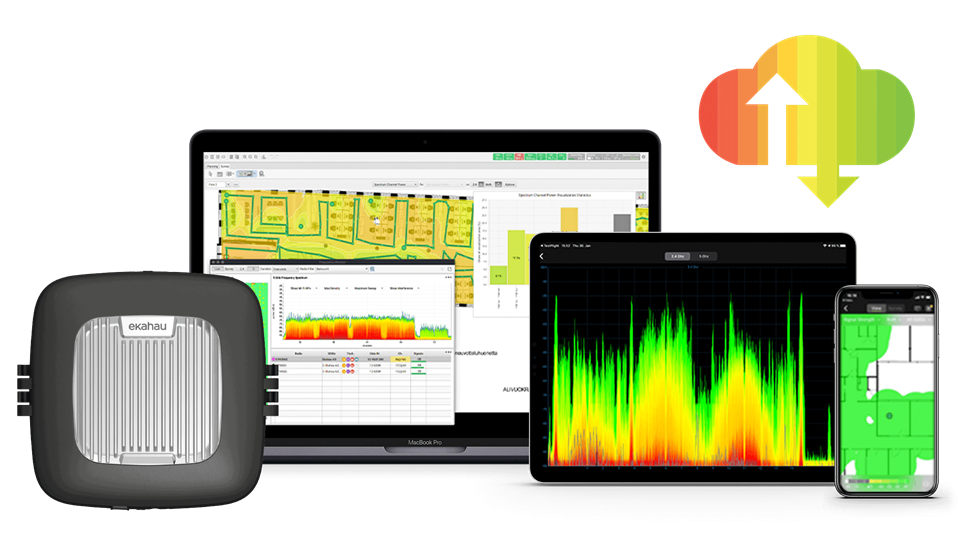
I use a software tool called ekahau. I used to use Air Magnet Survey Pro. Ekahau comes with a tool called a “side kick”. The sidekick is a device that collects Wi-Fi signals.
Let’s say we have a new building and we want to install a new wireless network. What will we do?
- We start by gathering basic information – the building floor plan, the areas that need Wi-Fi coverage, the user requirements, the security requirements, the way that the building was constructed, the types of vendors that the customer will permit (do they want Cisco, Meraki, HP, Aruba, etc.?)
- We walk around the facility to confirm the data that we gathered. We determine if there are area where wireless access points cannot be installed.
- Once we have an idea, we can import the floor plan into our survey software. We can draw out the areas that need coverage and tell the software where there are areas that will reduce coverage (such as metal shelves, concrete walls, etc.)
- We also tell the software the type of access points and antennas that we want to use
- The software runs a simulation that predicts the best spot each wireless access point. This is just a preliminary design. The software will show us a heat map that demonstrates the coverage. We can this adjust this design to add more wireless access points where there are many users (such as in conference rooms or classrooms). We can also move the wireless access points to more practical installation locations. The software adjusts the heat map each time we make a change.
- We then complete a Passive site survey. The passive site survey involves us walking around the building and collecting wireless signals automatically. The passive survey gives us a baseline idea of the noise in the environment. It should be completed during the day when many people and devices are active.
- We then complete an Active site survey. This is known as an AP on a Stick. Basically, we get a telescoping pole and mount an AP to the top, facing down. Then we power up the AP and place the stick at the first spot identified by our survey software.
We walk around and take measurements to determine whether the AP is providing adequate coverage. In other words, did the software correctly predict a good spot for the AP where we have at least -67 dBm and an SNR of at least 24?
Once we have gathered enough data, we move the AP on a Stick to the second location and take additional measurements. We continue to do this until we have placed the AP on a Stick at every location predicted by the software. - The software takes all the data that we collected and stiches it together. Then we can compare it against the original prediction. If the coverage determined during the survey is adequate, then we can proceed with installation. If not, we must make changes to the design and take additional measurements. This might be an iterative process until we get it 100% correct.
- Once we have the system installed and operational, we perform a final survey to verify that the system is operating in accordance with the original plan.
We can also survey an existing Wi-Fi network to determine whether it is operating correctly. At the end of that survey, we will have a plan to correct any issues we found.
On the user’s side a Wi-Fi connection can fail if the user attempts to connect to the wrong SSID, if the user has entered the wrong passphrase, or if he has selected the wrong type of security. The user’s computer and the Wi-Fi network must agree to the same security setting. If not, this is known as an encryption protocol mismatch.
Typically, a failure to connect will return a generic error on the user’s device but may return a more detailed error to the network administrator.
We should verify that the credentials are correct. We should attempt to clear or forget saved Wi-Fi networks and credentials. We should also update the network adapter drivers on the client device.